Abstract
This paper proposes a novel optimal current given (OCG) maximum power point tracking (MPPT) control strategy based on the theory of power feedback and hill climb searching (HCS) for a permanent magnet direct drive wind energy conversion system (WECS). The presented strategy not only has the advantages of not needing the wind speed and wind turbine characteristics of the traditional HCS method, but it also improves the stability and accuracy of MPPT by estimating the exact loss torque. The OCG MPPT control strategy is first carried out by simulation, then an experimental platform based on the dSPACE1103 controller is built and a 5.5 kW permanent magnet synchronous generator (PMSG) is tested. Furthermore, the proposed method is compared experimentally with the traditional optimum tip speed ratio (TSR) MPPT control. The experiments verify the effectiveness of the proposed OCG MPPT strategy and demonstrate its better performance than the traditional TSR MPPT control.
1. Introduction
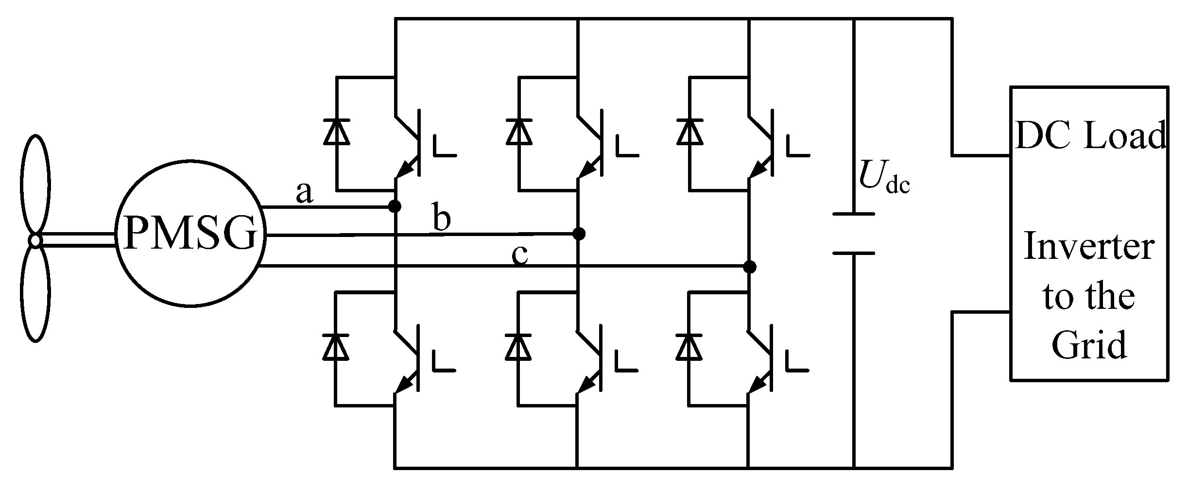
Renewable energy resources, especially wind energy, are attracting great attention with the depletion of existing fossil fuel deposits and increasing concerns about CO2 emissions. Since the late 1990s, variable speed constant frequency (VSCF) wind energy conversion systems (WECS) have been widely adopted in order to maximize wind energy utilization [1,2]. The doubly-fed induction generator (DFIG) and direct-drive permanent magnet synchronous generator (PMSG) are the most popular systems for VSCF wind energy conversion. The direct-drive PMSG has attracted more and more attention due to its advantages of high efficiency and high reliability. The configuration of a typical direct-drive WECS with PMSG is shown in Figure 1 [3,4,5]. The PMSG converts the mechanical power from the wind turbine into ac electrical power, which is then converted to dc power through a converter with a dc link to supply the dc load. By using an additional inverter, the PMSG can supply the ac electrical power with constant voltage and frequency to the power grid.
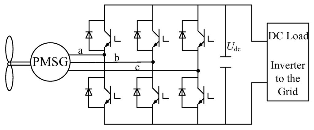
Figure 1.
Configuration of a direct-drive PMSG WECS.
Figure 1.
Configuration of a direct-drive PMSG WECS.
To maximize the use of wind energy when the wind speed is below the rated speed, the maximum power point tracking (MPPT) of the system is indispensable. The MPPT is realized by controlling the inverter which is connected to the generator. Previous research has focused on several types of MPPT methods, namely optimum tip speed ratio (TSR) control, hill climb searching (HCS) control, power feedback control and fuzzy-logic-based control [6,7,8,9,10,11,12].
The TSR method regulates the generator speed to maintain the optimum TSR. The control is easy to understand but hard to achieve due to the need to know the exact wind speed and wind turbine characteristics. HCS control on the other hand does not require any prior knowledge about the system and is absolutely independent of the turbine, generator and wind characteristics [13]. However, two serious problems with the HCS method are the speed-efficiency tradeoff and the wrong directionality under rapid wind change. The HCS strategy is optimized in some papers [13,14], but the algorithm and control procedure are commonly complex, which make it difficult to execute.
The power feedback control is implemented according to calculations based on the generator speed. The wind speed is not needed, but the wind turbine characteristics are indispensable [15]. Furthermore, the power losses should be considered in order to determine the accurate given maximum power. However, the power losses change with the generator rotor speed, which makes it difficult to determine the maximum power point accurately.
The fuzzy-control-based MPPT scheme is good, but somewhat complex to implement [8]. However, the adaptive fuzzy controller for MPPT control designed by Galdi et al. in [16,17,18] can implement sensorless peak power tracking and overcome some disadvantages of classical methods. The maximum power can be estimated through a Takagi-Sugeno-Kang (TSK) fuzzy controller by measuring the rotor speed and power generated by the generator without measuring wind speed and wind turbine parameters.
To overcome these drawbacks of the traditional HCS and power feedback MPPT methods, some effective measures are taken in this paper. Its objective is to present an effective optimum current given (OCG) MPPT method combining the advantages of the power feedback method and the HCS method without knowing the wind speed and turbine characteristics. Besides, the proposed method can extract the maximum power point more exactly and steadily than traditional HCS control, especially when the wind speed changes quickly. Furthermore, the MPPT control will not be influenced by the change of power losses through estimating the exact loss torque compared to the power feedback MPPT. The proposed MPPT method is implemented in a WECS based on a PMSG and compared with the traditional TSR control to verify the MPPT efficiency. The experimental results demonstrate the feasibility and effectiveness of the proposed strategy.
2. Wind Turbine Model
2.1. Wind Turbine Model
The mechanical power extracted by a wind turbine can be given by:
where ρ is the air density, R is the radius of turbine blades, v is the wind velocity, and Cp is the power coefficient which is a nonlinear function of the tip speed ratio λ and the blade pitch angle β. λ is defined as:
where ωr is angular speed of the rotor.
Based on (1) and (2), the torque output by wind turbine can be expressed as:
The Cp versus tip speed ratio (TSR) curve is shown in Figure 2 by assuming that the blade pitch angle β is constant. According to (2), the rotor speed can be regulated to keep λ remain the optimum value λopt and then the power efficient remain the maximum value Cpmax.
The maximum power output by wind turbine is given by:
and then the maximum torque is:
where kopt is a constant determined by the wind turbine characteristics.
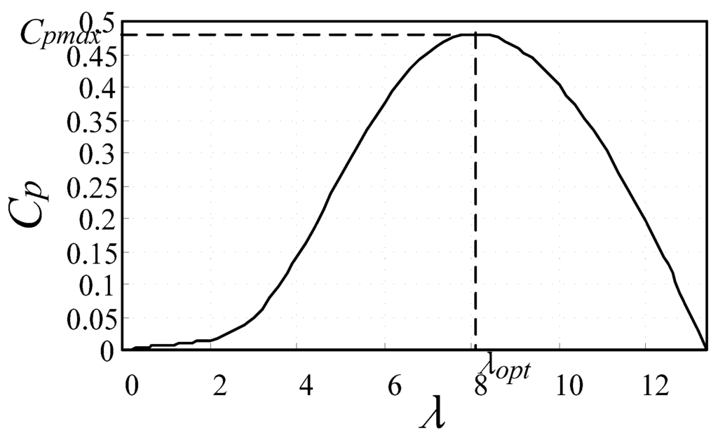
Figure 2.
Curve of Cp-λ.
Figure 2.
Curve of Cp-λ.
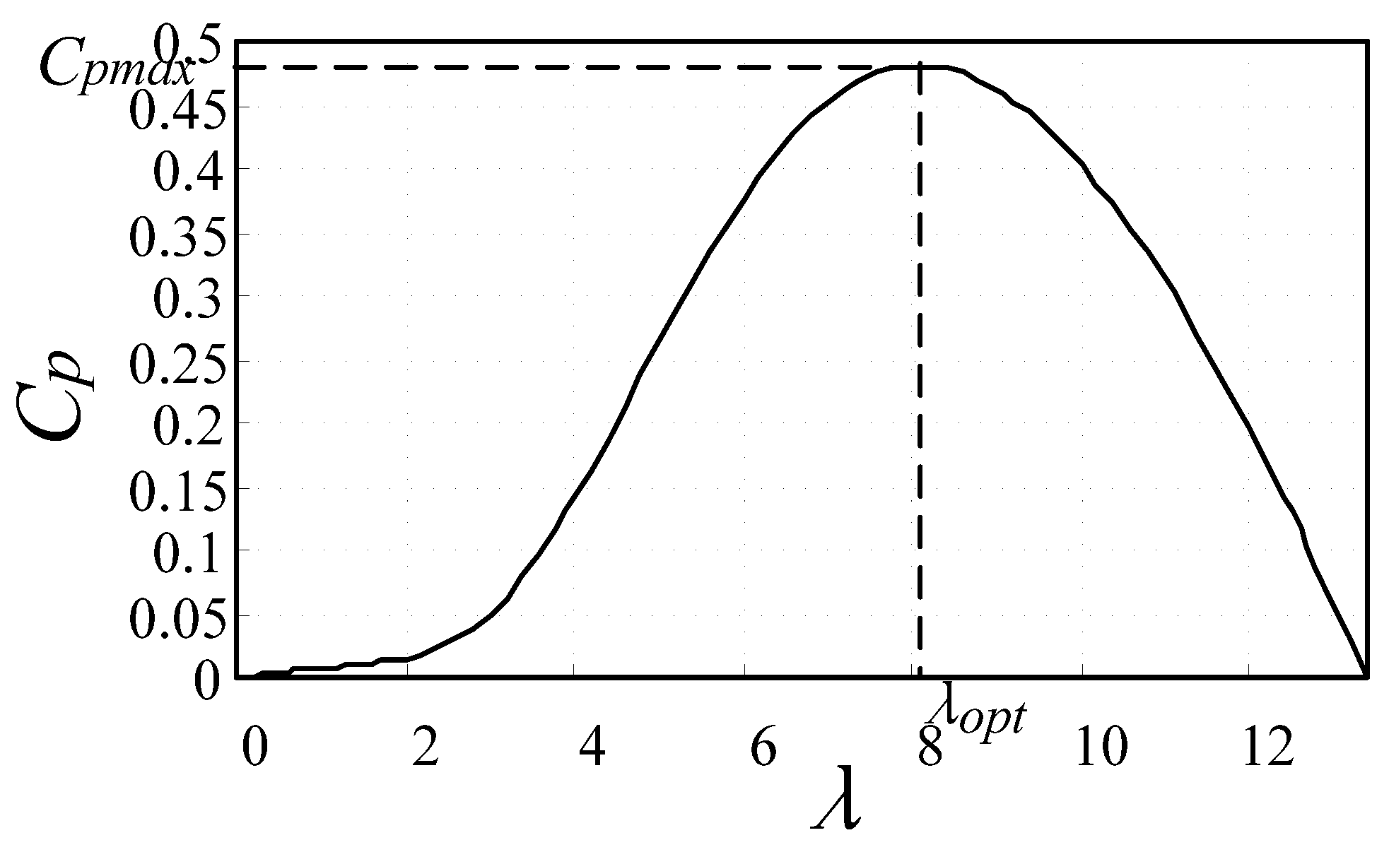
Figure 3a illustrates the power versus rotor speed curves calculated by Equations (1) and (2) when the wind speed varies. From the power versus speed curves, the torque versus speed characteristics curves shown in Figure 3b are obtained. The maximum power curve and maximum torque curve are shown with dotted lines in Figure 3a and Figure 3b, respectively. As shown in Figure 3a, if the wind speed is v1 the maximum power would be captured when the rotor speed is ωr1 and the system operating point is A. When the wind speed changes from v1 to v2 and the rotor speed is fixed at ωr1, but the system operating point jumps to B, which does not correspond to the maximum power tracking. Then the rotor speed should be controlled to increase from ωr1 to ωr2 which results in the maximum power at operating point C. The torque operating point shown in Figure 3b is in accordance with power operating point shown in Figure 3a.

Figure 3.
Wind turbine characteristics (a) Power versus rotor speed; (b) Torque versus rotor speed.
Figure 3.
Wind turbine characteristics (a) Power versus rotor speed; (b) Torque versus rotor speed.

2.2. PMSG Model
The voltage equations of the PMSG in dq-axes rotating reference frame [19] are:
where uds, uqs are the stator winding voltages in dq-axes. ids, iqs are the stator winding currents in dq-axes. ψds, ψqs are the stator winding magnet fluxes in dq-axes. ωe is the rotor speed, and Rs is the resistances of the stator winding.
The magnet flux equations of PMSG in a dq-axes rotating reference frame are given by:
where ψf is the permanent magnet flux. Ld, Lq are the stator winding inductances in dq-axes.
The steady state power of the PMSG can be derived based on Equations (6) and (7) as:
Obviously, the first term of (8) is the copper losses of the PMSG, then the electromagnetic torque of PMSG can be obtained by considering the copper losses and the equation is expressed as:
where np is the pole pairs of the PMSG, ωr is the mechanical rotor speed of PMSG.
3. Proposed MPPT Algorithm
3.1. OCG MPPT Method
The novel MPPT control strategy in this paper is proposed based on the theory of the conventional power feedback control and HCS control. According to (4), the maximum power of the wind turbine Pmax is a cubic function of the generator speed. Traditional power feedback control meets the maximum power point by measuring the output power or the output torque and regulates it based on the cubic or square of generator speed. Although the optimal power can be calculated easily, however, the power or torque feedback loop will reduce the MPPT response speed and accuracy due to the quickly changing wind and the inertia of the mechanical system. Also, as mentioned before, the power losses which vary with the wind speed cannot be ignored and are difficult to estimate exactly.
Therefore, the optimum current given (OCG) MPPT control strategy is proposed here based on the PMSG model for improving the traditional power feedback method. id = 0 current control strategy is commonly used for the vector control for the PMSG due to the simplicity and effectiveness [20]. When adopting id = 0 control, (9) can be simplified as:
Then the electromagnetic torque is only determined by the q-axis current iqs assuming that the permanent magnet flux is constant. Therefore, the PMSG can obtain the optimum torque by giving the optimum iqs. Furthermore, the maximum power point can be achieved when the torque versus speed meets the optimum curve shown in Figure 3b. In other words, the MPPT can be realized when the optimum iqs is given.
The iron loss, copper loss, mechanical loss and stray loss cannot be ignored when the PMSG is in operation. As shown in (8) and (9), the copper loss has been considered in the derivation of the electromagnetic torque. Then only the iron loss, mechanical loss and stray loss are associated with the loss torque expressed as Tloss. The loss torque can be divided as:
The iron loss mainly varies along with the generator speed, so the iron loss torque Tloss_Fe, which equals iron loss divided by speed, remains relatively constant. The mechanical loss and the stray loss only account for a small percentage of the total losses, thus the mechanical loss torque Tloss_m and the stray loss torque Tloss_s can be regarded as constant values. Therefore, the loss torque Tloss basically remains constant in operation.
The maximum torque of PMSG calculated by (5) is an ideal value and the actual maximum electromagnetic torque Te* can be expressed as:
According to the aforementioned equations, the optimum current can be derived as:
3.2. Estimation of Tloss
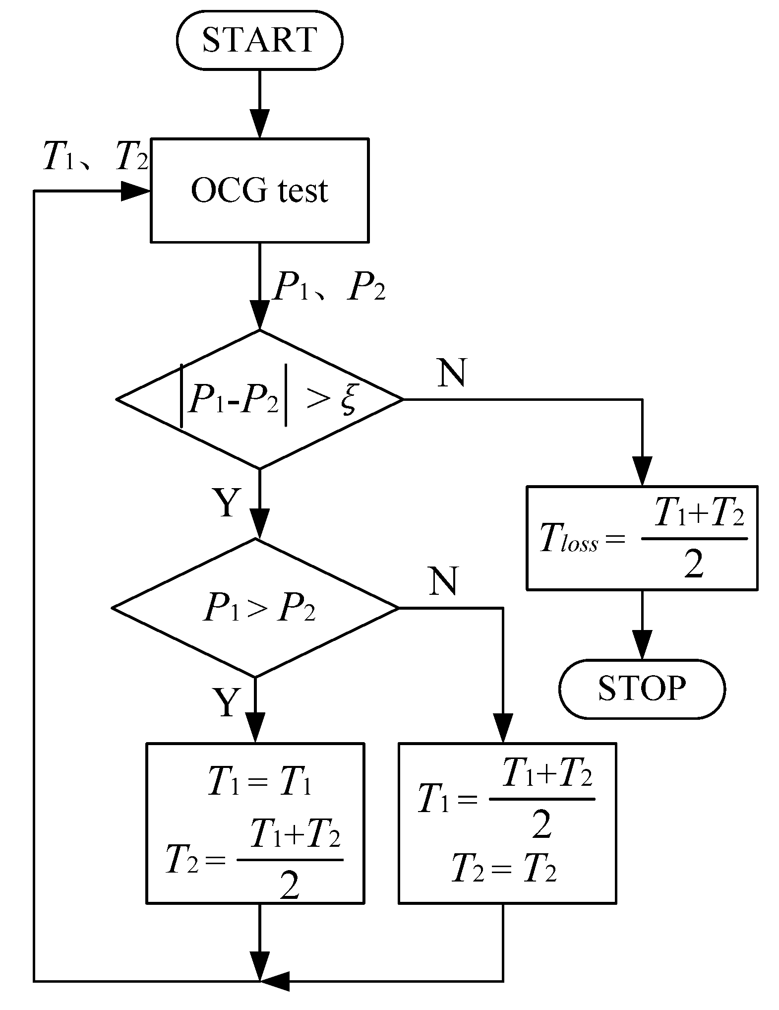
In the experiment, Tloss can be obtained based on the theory of dichotomy according to the characteristics of the PMSG. Based on the wind characteristics, a maximum power generated by the PMSG corresponds to a constant wind speed. The maximum loss torque T1 and minimum loss torque T2 are given first to be applied in the OCG MPPT on the basis of the experience and machine characteristics. Then the generated powers P1 and P2 by the PMSG under these two loss torques can be observed and compared. One of the next boundary loss torque values can be confirmed according to the result of comparing the two generated powers P1 and P2.
The OCG tests will not stop until the difference between the two generated powers is less than a given constant value ξ. Then the fairly accurate Tloss can be obtained after several tests. The detailed loss torque estimation principle can be seen from the flow chart shown in Figure 4.
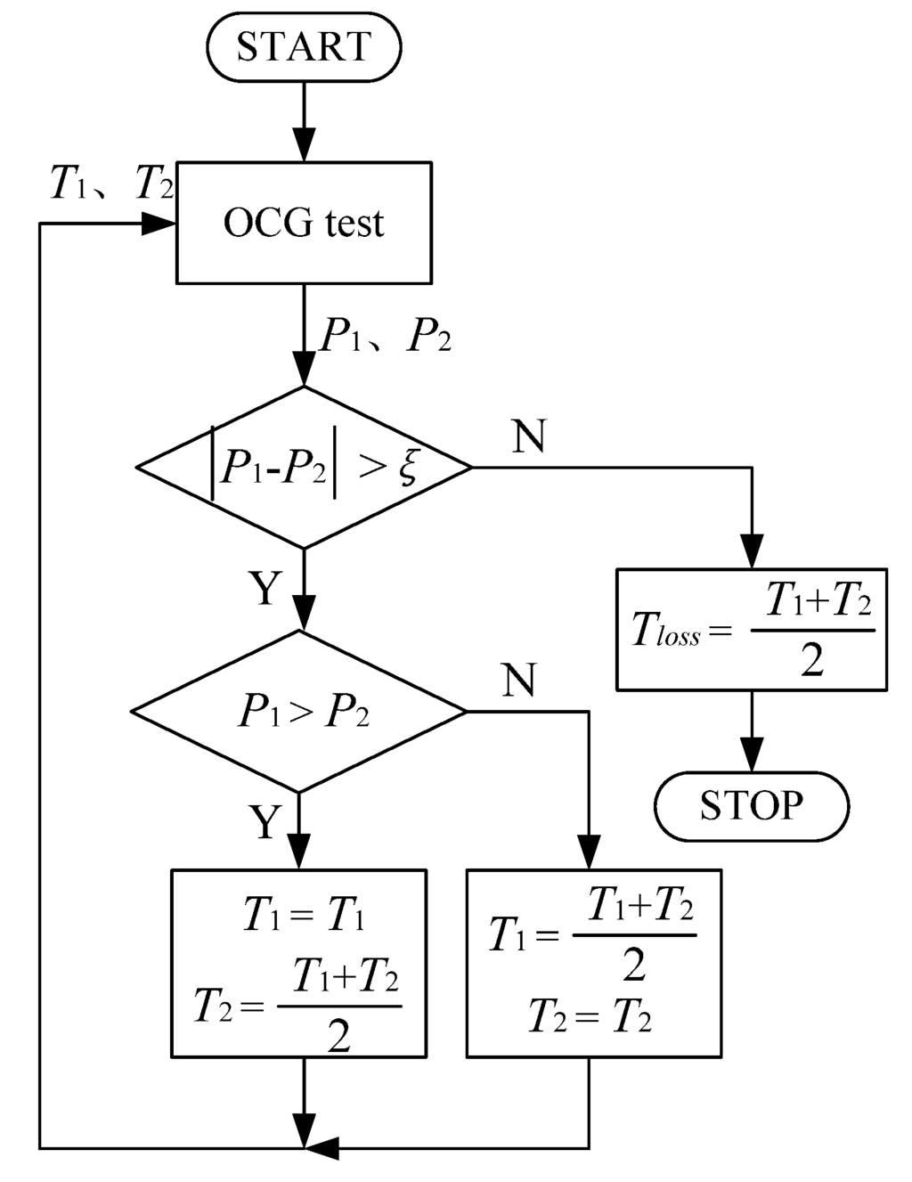
Figure 4.
Flow chart of the Tloss estimation algorithm.
Figure 4.
Flow chart of the Tloss estimation algorithm.
3.3. kopt Obtained by HCS MPPT Method
The optimum current given control method still has the problem that the constant coefficient kopt is determined by the wind turbine and therefore not so easy to measure. Furthermore, as time goes on, the wind turbine characteristics will change a little which is influenced by the external environments, then the kopt will be labile.
The conventional HCS method can reach the maximum power point (MPP) without the need of kopt as shown in Figure 5. Once the peak is detected and extracted, the coefficient kopt can be calculated and serve for the optimum current given MPPT control.
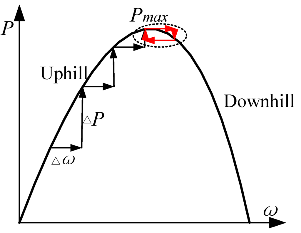
Figure 5.
HCS control algorithm.
Figure 5.
HCS control algorithm.
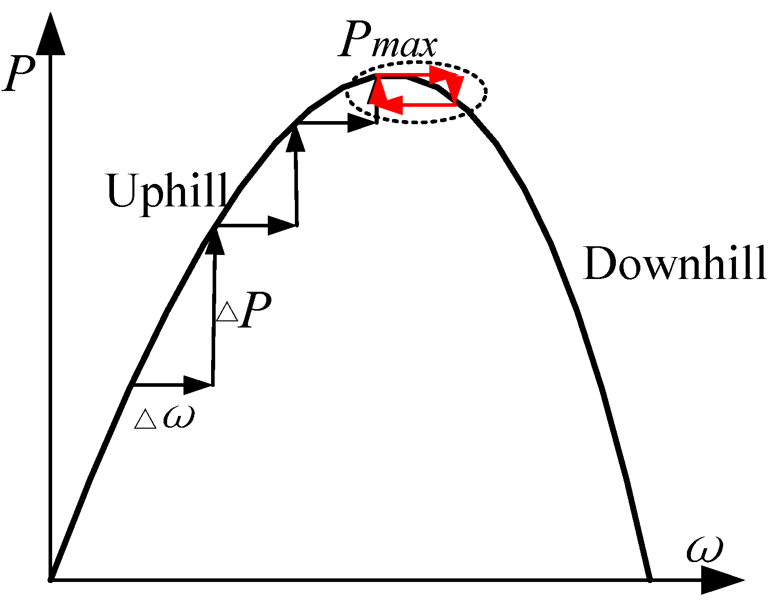
However, traditional HCS method cannot stop searching when the climbing reaches the MPP then the speed oscillates around the MPP as shown in Figure 5 with the red line labels [7]. Here two checking rules are given to ensure the MPP is detected accurately. The two checks are given as follows:
The first rule (14) means that the power variation ΔP(k) should be less than a threshold δ. The second rule (15) means that the gradient of the ω versus P curve should be less than a threshold θ. The climbing search will be stopped when both the two checks are true and then the MPP is detected. According to the actual environment of the wind fields, the improved HCS could be applied to obtain the kopt for some time which will ensure the accuracy of the MPPT control.
3.4. Proposed MPPT Method
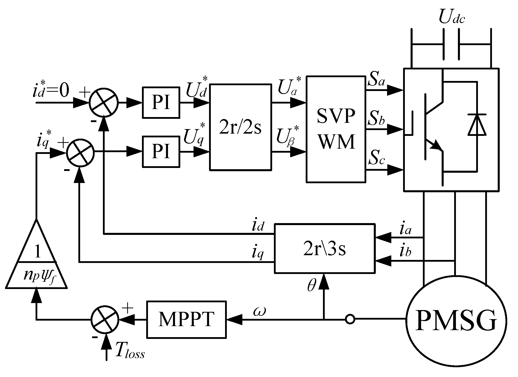
After the coefficient kopt is detected the optimum current given by MPPT can be applied successfully with no need of the wind characteristics. The control configuration of the PMSG with OCG MPPT is shown in Figure 6. The generator speed is measured to calculate the optimum torque and then obtain the optimum current. Only the double current loops are needed in this MPPT strategy. Compared to the power feedback control method which needs the power loop, the proposed method is more convenient and responds more quickly.
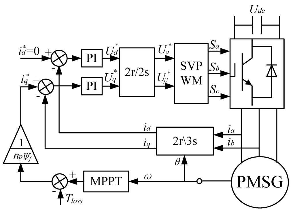
Figure 6.
PMSG control configuration with the proposed OCG MPPT.
Figure 6.
PMSG control configuration with the proposed OCG MPPT.
3.5. Imitation of Wind Turbine
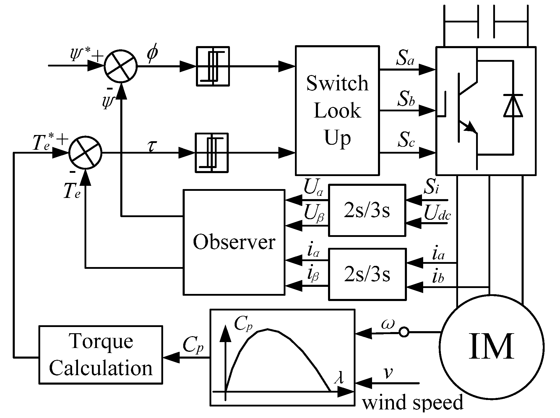
Wind turbine imitation is indispensable in the experiment for the MPPT strategy verification. In this paper, an induction machine (IM) is used to imitate the wind turbine. Based on the imitation principle of wind turbine and the direct torque control (DTC) theory [21], the control scheme of IM can be obtained as shown in Figure 7.
The given torque of IM is decided by the wind speed and the actual generator speed according to Equations (2), (3) and Figure 2. The IM with direct torque control can imitate the wind turbine well due to the fast response and superior dynamics.
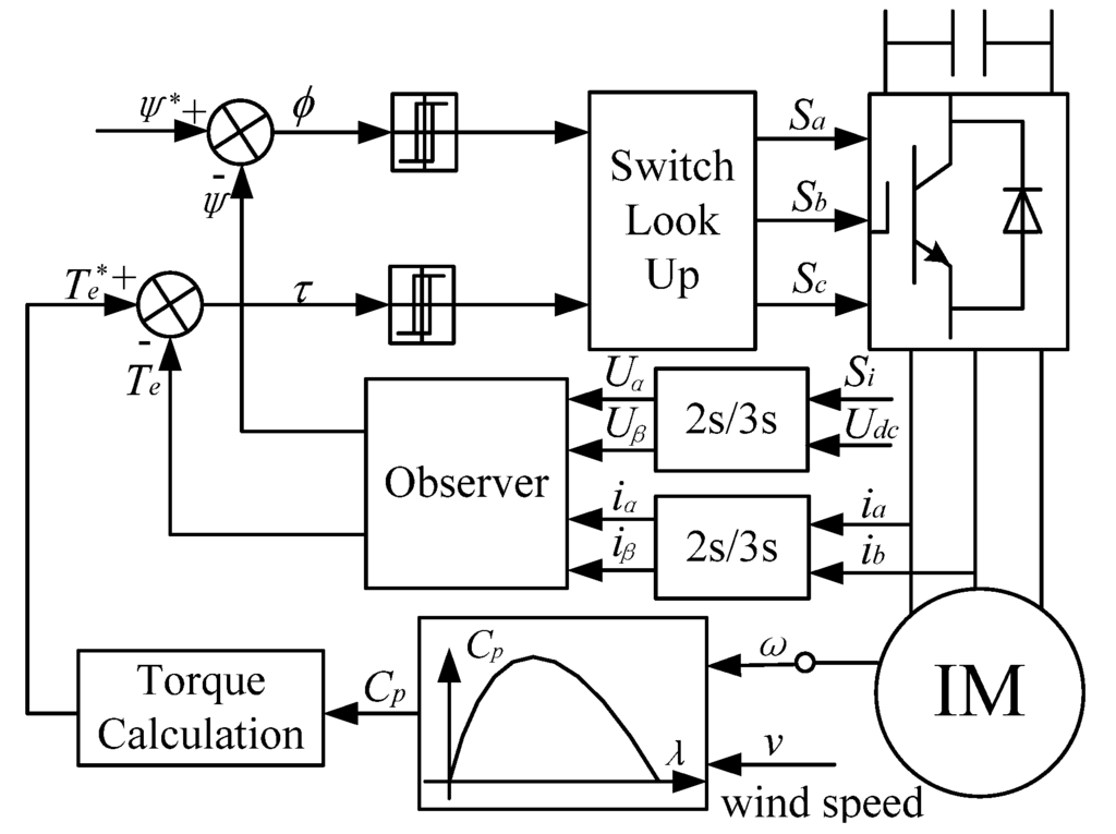
Figure 7.
Control configuration of IM with DTC control.
Figure 7.
Control configuration of IM with DTC control.
4. Simulation Results
4.1. Simulation Parameters
The parameters in the simulation are as the same as the those in the experiment. The PMSG and IM parameters are given in Table 1. The wind turbine parameters are: the air density ρ = 1.225 kg/m3, turbine rotor radius R = 1.2 m, optimum tip speed ratio λopt = 8.1, and optimum power coefficient Cpmax = 0.48.

Table 1.
Machine parameters.
| PMSG Item | Value | IM Item | Value |
|---|---|---|---|
| Rated power (kW) | 5.5 | Rated power (kW) | 5.5 |
| Resistance (Ω) | 0.665 | Stator resistance (Ω) | 0.628 |
| d-axis inductance (mH) | 7.93 | Rotor resistance (Ω) | 1.192 |
| q-axis inductance (mH) | 7.93 | Stator leakage inductance (mH) | 5.668 |
| Torque coefficient (kg·m2) | 0.04 | Rotor leakage inductance (mH) | 5.668 |
| Permanent Magnet flux-linkage (Wb) | 0.783 | Mutual inductance (H) | 0.1639 |
| Pole pairs | 2 | Pole pairs | 2 |
4.2. Simulation of HCS
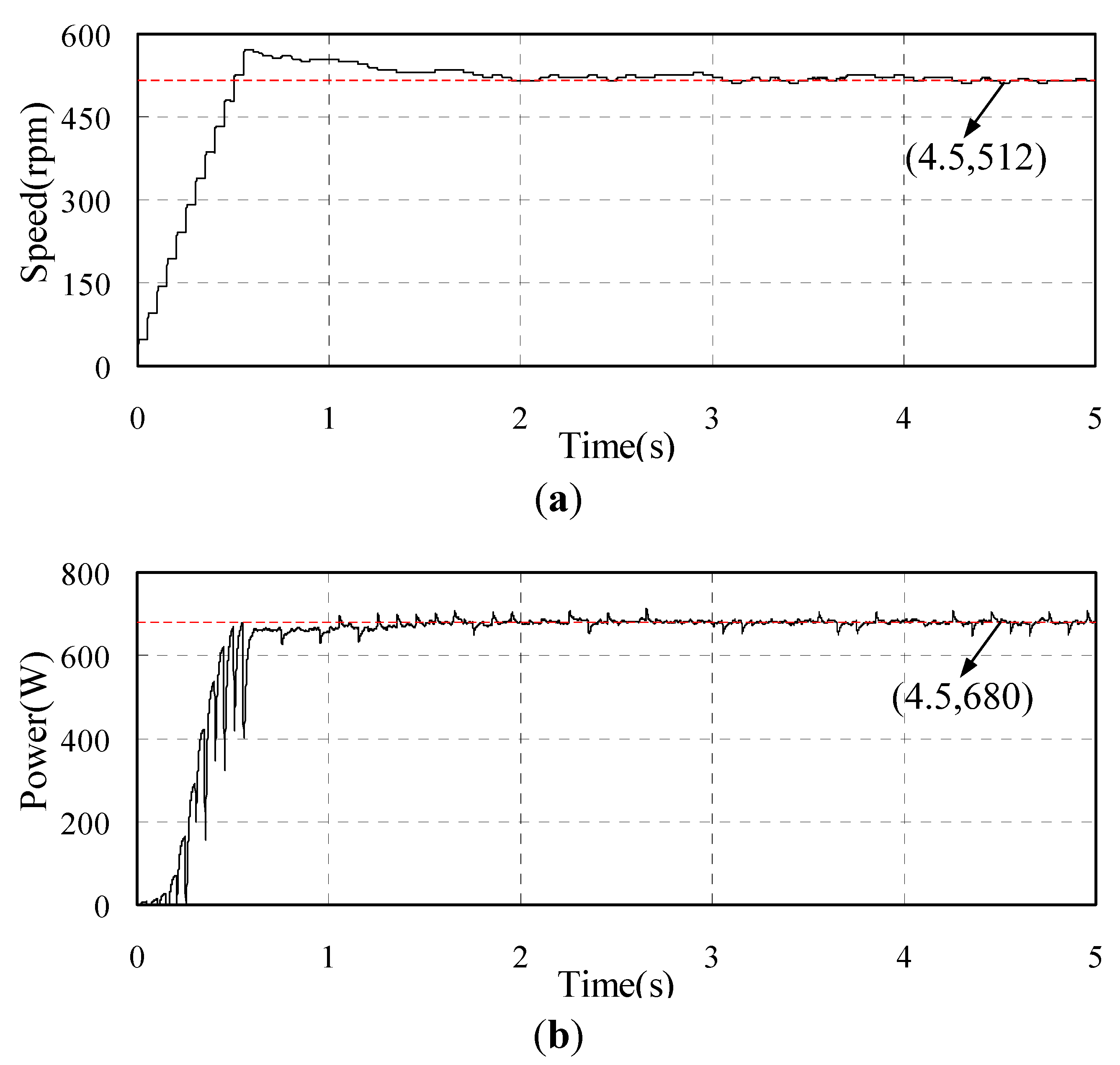
In order to obtain the coefficient kopt, the HCS method is adopted first. The simulation results of the PMSG with HCS MPPT is shown in Figure 8 for when an unknown wind speed is given. Figure 8a shows the speed of the PMSG which stabilizes two seconds later. The output power of PMSG is shown in Figure 8b varies with the speed. At the 4.5 s point, the speed is 512 rpm and the output power is 680 W. Then the kopt can be calculated according to (4) and the value is 0.00441.
In the simulation the actual wind turbine parameters are given as shown in Table 1 in the wind turbine imitation. Then we can calculate that the real kopt is 0.00432. It can be found that the kopt obtained by the HCS control is very close to the actual value. Therefore, the proposed OCG MPPT strategy can work out based on the above calculation method.
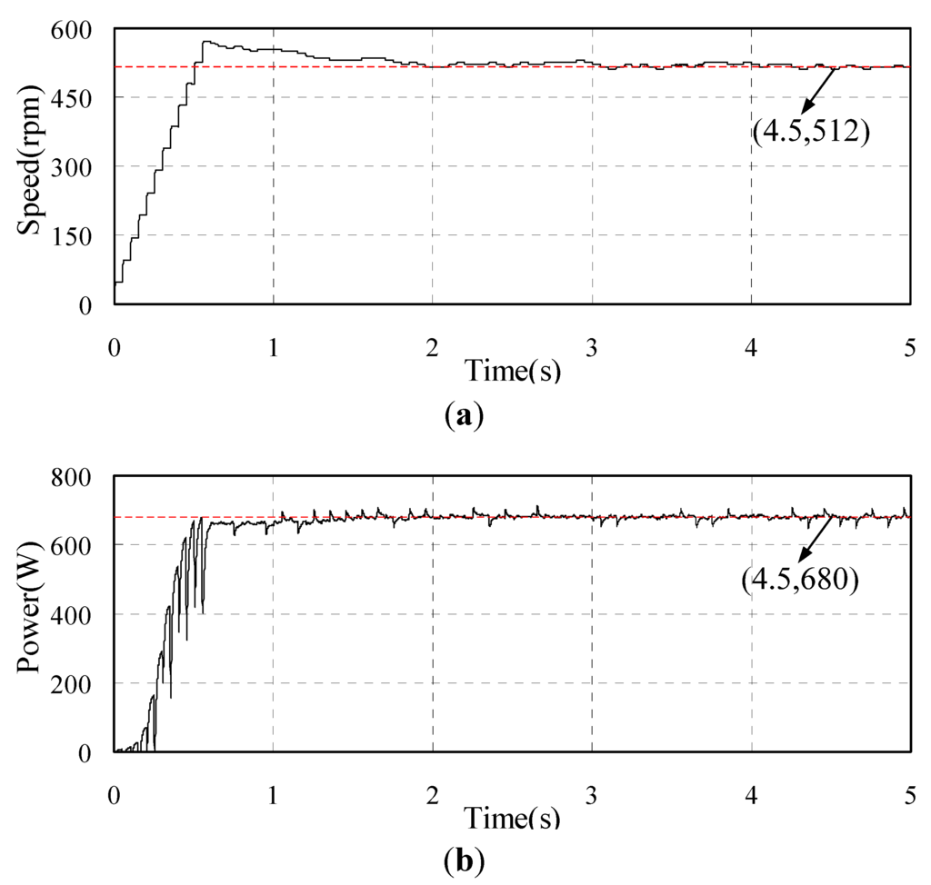
Figure 8.
Simulated waveforms of PMSG with HCS MPPT (a) Rotor speed of PMSG; (b) Output power of PMSG.
Figure 8.
Simulated waveforms of PMSG with HCS MPPT (a) Rotor speed of PMSG; (b) Output power of PMSG.
4.3. Simulation Results of OCG MPPT
The stochastic wind speed which is generated by the professional software Turbsim is applied for the simulation. The iron loss, mechanical loss and stray loss cannot be given correctly in the simulation model. Then the loss torque Tloss is hard to simulate thus it is ignored in the simulation. The proposed strategy by considering the losses are verified in the experiment.
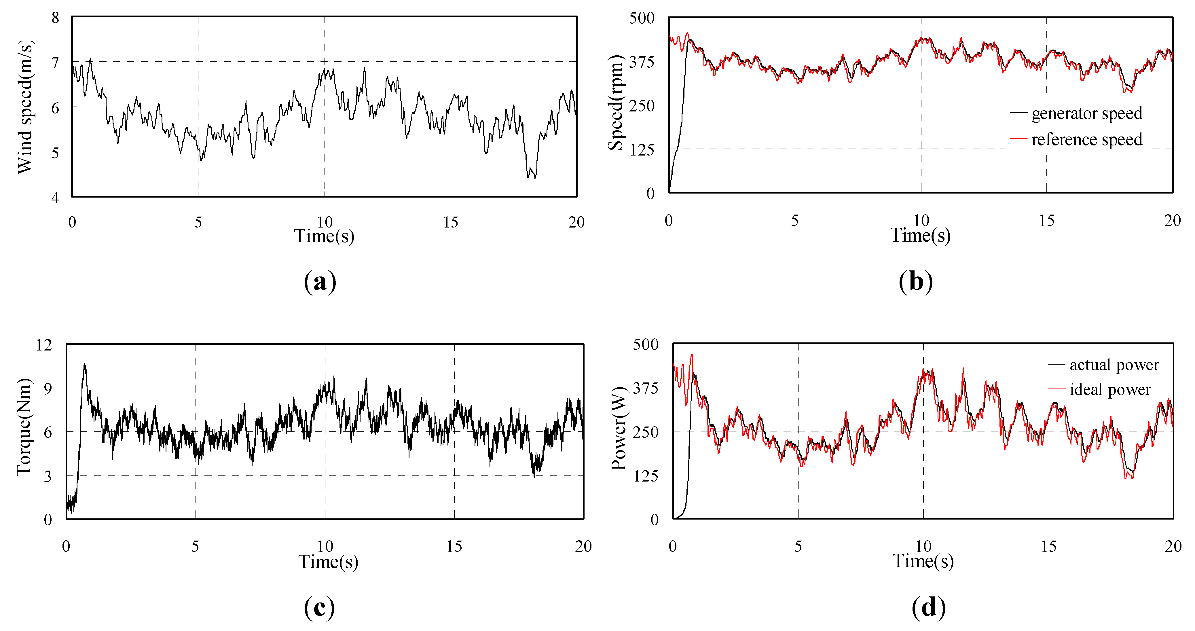
The simulation results of PMSG under the proposed OCG MPPT control are shown in Figure 9. The stochastic wind speed is shown in Figure 9a. From Figure 9b, it can be observed that the generator speed can follow the reference speed well. The torque shown in Figure 9c varies with the generator speed. Figure 9d presents the generated power which is consistent with the ideal maximum power.
The simulation results demonstrate the feasibility and effectiveness of the proposed OCG MPPT strategy based on the HCS method when the system losses are ignored.
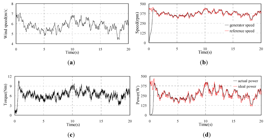
Figure 9.
Simulated waveforms of PMSG with OCG MPPT (a) Wind speed; (b) Rotor speed of PMSG; (c) Torque of PMSG; (d) Output power of PMSG.
Figure 9.
Simulated waveforms of PMSG with OCG MPPT (a) Wind speed; (b) Rotor speed of PMSG; (c) Torque of PMSG; (d) Output power of PMSG.
5. Experimental Results
5.1. Experimental Platform
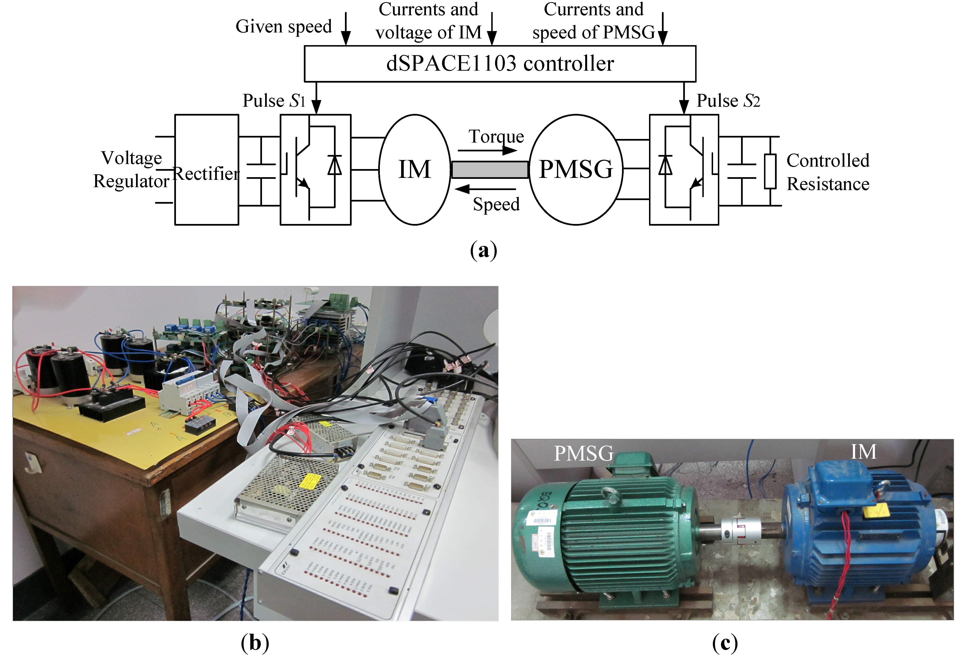
Experimental studies are made to verify the proposed OCG MPPT based on the successful simulation. The configuration of the experimental platform is shown in Figure 10 which is composed of wind turbine imitation and wind energy generation. The system of wind turbine imitation consists of a three phase voltage regulator, a diode rectifier, a three phase inverter, a capacity and the IM. The wind energy generation system consists of the PMSG, a three phase inverter, a capacitor and a controlled resistance. The controlled resistance is turned on or off according to the dc voltage in PMSG side. The dc voltage remains relatively constant and the generated power is consumed by the resistance. The controls of the IM, PMSG and controlled resistance are all based on the dSPACE1103 platform.
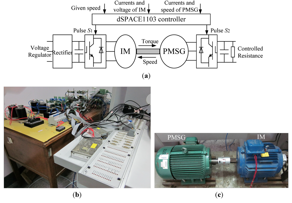
Figure 10.
Experimental platform (a) Configuration; (b) Control platform; (c) Experimental machines.
Figure 10.
Experimental platform (a) Configuration; (b) Control platform; (c) Experimental machines.
5.2. Experimental Results
The experimental parameters are consistent with that in the simulation. The 600 s stochastic wind speed is generated by software Turbsim and output to the dSPACE control platform to simulate the actual wind speed.
Similar to the simulation, the HCS MPPT is first applied to obtain the kopt which is calculated as 0.00421. The experimental value is less than the actual given value due to the losses in the experiment. The loss torque of the system is estimated according to the principle presented in the flow chart shown in Figure 4. During several tests, the loss torque Tloss is estimated as 0.7 Nm.
Then the proposed OCG MPPT is adopted and the experiment results are shown in Figure 11(a–e). The wind speed is shown in Figure 11a in 20 s. The generator speed shown in Figure 11b can follow the reference speed but not fully coincide. Figure 11c shows the iq of the PMSG which changes fairly smoothly. The torque and output power shown in Figure 11d and Figure 11e have small fluctuations. The actual generated power is lower than the ideal power due to the system losses, but the actual value remains close to the ideal value, which means the MPPT control is realized.
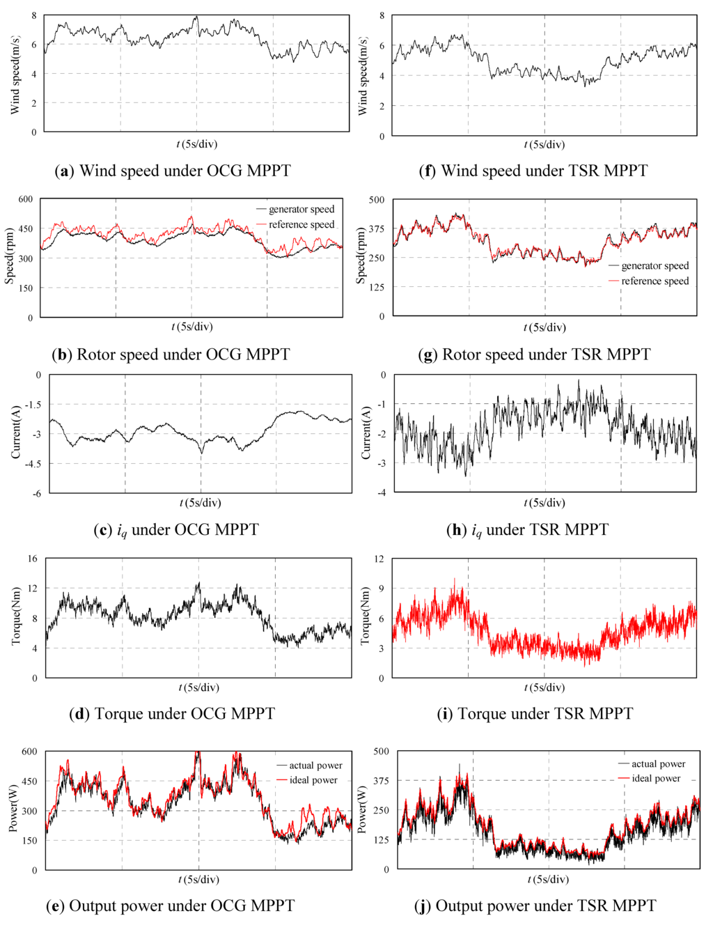
Figure 11.
Experimental waveforms of PMSG with proposed OCG MPPT and TSR MPPT.
Figure 11.
Experimental waveforms of PMSG with proposed OCG MPPT and TSR MPPT.
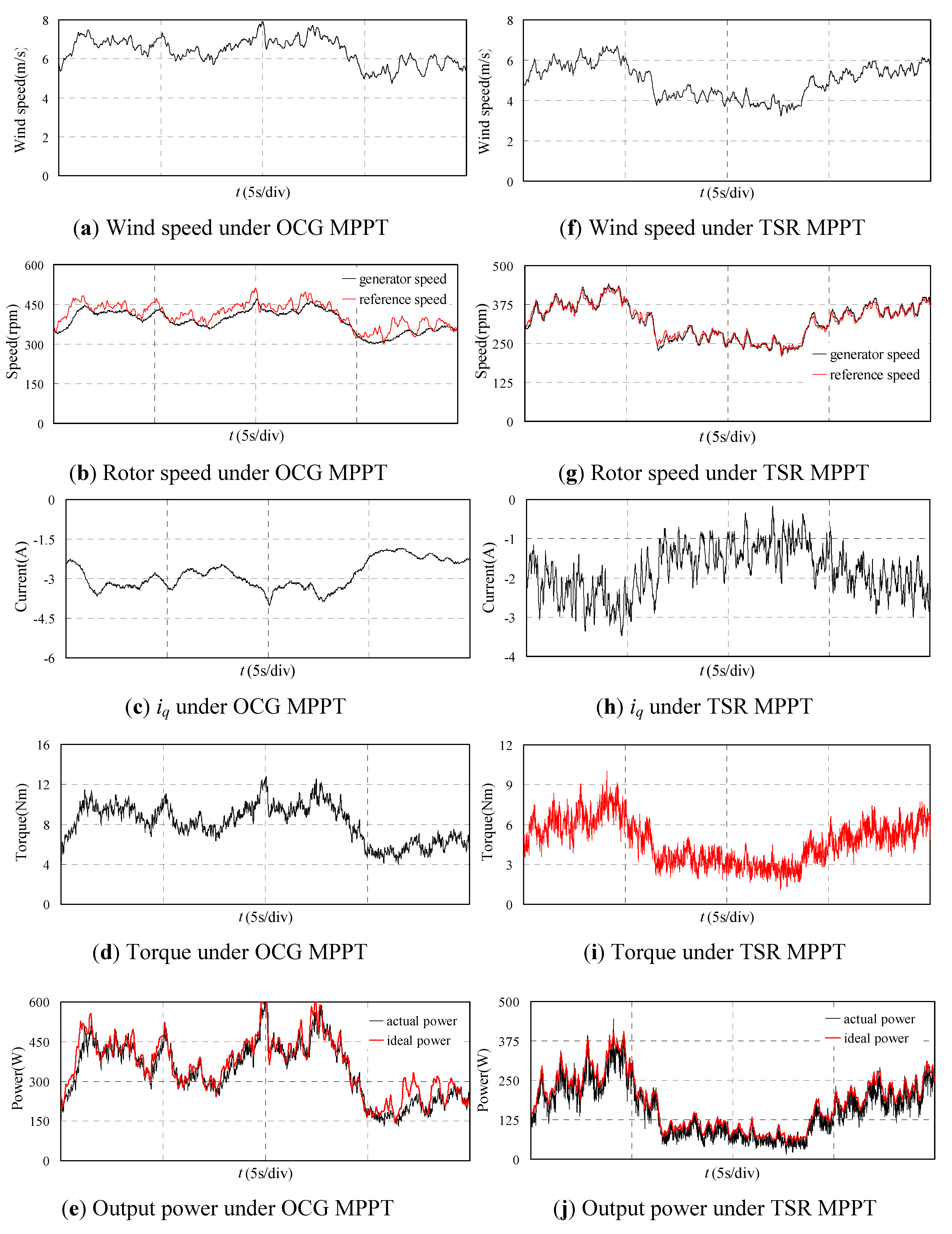
For comparison, the traditional TSR MPPT control is also carried out and the results are shown in Figure 11(f–j). It should be noted that the wind speed for TSR MPPT is different form that for OCG MPPT because the collection of the experimental results can’t be at the same time in the 600 s. The wind speed is shown in Figure 11(f) in 20 s. The generator speed shown in Figure 11(g) verifies the good effect of MPPT due to the actual generator speed coinciding with the reference optimum speed. Figure 11(h) shows the iq of PMSG which fluctuates widely due to the variation of the wind speed. The torque and output power shown in Figure 11(i) and Figure 11(j) also fluctuate widely. Figure 11(j) also shows that the MPPT control effect is good, though the actual generated power is lower than the ideal power due to the losses.
The experimental results show that both of the two strategies can realize the MPPT control well but the generator torque and the output power under the proposed OCG strategy are smoother. Therefore, the drive train mechanical stresses will be reduced by adopting the proposed method. Furthermore, the efficiency of the proposed MPPT method can be fully comparable to that of the TSR MPPT method.
6. Conclusions
This paper proposed a novel optimum current given MPPT control method for a permanent magnet direct drive wind energy conversion system. The strategy is based on the idea of the power feedback MPPT method and traditional HCS MPPT method and combines the advantages of both of them. A method for estimating the system loss torque is proposed and the improved HCS method is adopted periodically to ensure obtaining the exact wind turbine parameters.
The traditional power feedback MPPT needs the characteristics of the wind turbines. Besides, the given optimum power which is changed due to the change of the losses varying with the generator speed which will reduce the effectiveness of the MPPT control. The HCS MPPT will deteriorate its performance under rapidly changing wind conditions. The maximum power coefficient kopt is obtained by improved HCS MPPT. Then the optimum current given MPPT is adopted with no need of the wind turbine characteristics. The loss torque used in the proposed method can be regarded as a constant and the MPPT effectiveness will not be influenced by the generator speed.
For verifying the effectiveness of the proposed MPPT method, simulation models are built and experiments are carried out. Both simulation and experimental results demonstrate that the proposed MPPT method is effective under the environment with quickly changing wind speed. Furthermore, the proposed strategy is compared with the traditional TSR method in the experiment and the results show that the generated power with the proposed MPPT control is comparable with the TSR method which tracks the optimum value in real time. Besides, the output power pulsation of the proposed method is smaller than the TSR method.
Acknowledgments
This work is supported in part by grants from the National Natural Science foundation of China (Project No. 50977011, 51137001), Innovative Scholar Ascent Program of Jiangsu Province, China (Project No. BK2010013) and Scientific Research innovation plan for Graduate students in Jiangsu Province of 2011 (Project No. CXLX_0109).
References
- Polinder, H.; Van der Piji, F.F.A.; De Vilder, G.J.; Tavner, P.J. Comparison of direct-drive and geared generator concepts for wind turbines. IEEE Trans. Energy Convers. 2006, 21, 725–733. [Google Scholar] [CrossRef]
- Li, H.; Chen, Z. Overview of different wind generator systems and their comparisons. IET Renew. Power Gener. 2008, 2, 123–138. [Google Scholar] [CrossRef]
- Liserre, M.; Cardenas, R.; Molinas, M.; Rodriguez, J. Overview of multi-MW wind turbines and wind parks. IEEE Trans. Ind. Electron. 2011, 58, 1081–1095. [Google Scholar] [CrossRef]
- Haraguchi, H.; Morimoto, S.; Sanada, M. Suitable design of a PMSG for a large-scale wind power generator. In Proceedings of Energy Conversion Congress and Exposition, San Jose, CA, USA, 20–24 September 2009; pp. 2447–2452.
- Zhang, S.; Tseng, K.; Vilathgamuwa, M.; Nguyen, D. Design of a robust grid interface system for PMSG-based wind turbine generators. IEEE Trans. Ind. Electron. 2010, 58, 316–328. [Google Scholar] [CrossRef]
- Arifujjaman, M.; Lqbal, M.T.; Quaicoe, J.E. A comparative study of the reliability of the power electronics in grid connected small wind turbine systems. In Proceedings of Electrical and Computer Engineering Conference, St. John’s, Canada, 3–6 May 2009; pp. 394–397.
- Abdullah, M.A.; Yatim, A.H.M.; Tan, C.W.; Saidur, R. A review of maximum power point tracking algorithms for wind energy systems. Renew. Sustain. Energy Rev. 2012, 16, 3220–3227. [Google Scholar] [CrossRef]
- Agarwal, V.; Aggarwal, R.K.; Patidar, P.; Patki, C. A novel scheme for rapid tracking of maximum power point in wind energy generation systems. IEEE Trans. Energy Convers. 2010, 25, 228–236. [Google Scholar] [CrossRef]
- Tan, K.; Islam, S. Optimal control strategies in energy conversion of PMSG wind turbine system without mechanical sensors. IEEE Trans. Energy Convers. 2004, 19, 392–399. [Google Scholar] [CrossRef]
- Pahlevaninezhad, M.; Eren, S.; Bakhshai, A.; Jain, P. Maximum power point tracking of a Wind Energy Conversion System using adaptive nonlinear approach. In Proceedings of Applied Power Electronics Conference and Exposition, Palm Springs, CA, USA, 21–25 February 2010; pp. 149–154.
- Haque, M.E.; Negnevitsky, M.; Muttaqi, K.M. A novel control strategy for a variable-speed wind turbine with a permanent-magnet synchronous generator. IEEE Trans. Ind. Appl. 2010, 46, 331–339. [Google Scholar] [CrossRef]
- Kun, H.; Guo-Zhu, C. A novel control strategy of wind turbine MPPT implementation for direct-drive PMSG wind generation imitation platform. In Proceedings of Power Electronics and Motion Control Conference, Wuhan, China, 17–20 May 2009; pp. 2255–2259.
- Kazmi, S.M.R.; Goto, H.; Guo, H.J.; Ichinokura, O. A novel algorithm for fast and efficient speed-sensorless maximum power point tracking in wind energy conversion systems. IEEE Trans. Ind. Electron. 2011, 58, 29–36. [Google Scholar] [CrossRef]
- Quincy, W.; Liuchen, C. An intelligent maximum power extraction algorithm for inverter-based variable speed wind turbine systems. IEEE Trans. Power Electron. 2004, 19, 1242–1249. [Google Scholar] [CrossRef]
- Morimoto, S.; Nakayama, H.; Sanada, M.; Takeda, Y. Sensorless output maximization control for variable-speed wind generation system using IPMSG. IEEE Trans. Ind. Appl. 2005, 41, 60–67. [Google Scholar] [CrossRef]
- Galdi, V.; Piccolo, A.; Siano, P. Designing an adaptive fuzzy controller for maximum wind energy extraction. IEEE Trans. Energy Convers. 2008, 23, 559–569. [Google Scholar] [CrossRef]
- Calderaro, V.; Galdi, V.; Piccolo, A.; Siano, P. A fuzzy controller for maximum energy extraction form variable speed wind power generation systems. Electr. Power Syst. Res. 2007, 78, 1109–1118. [Google Scholar] [CrossRef]
- Galdi, V.; Piccolo, A.; Siano, P. Exploiting maximum energy from variable speed wind power generation systems by using an adaptive Takagi-Sugeno-Kang fuzzy model. Energy Convers. Manag. 2009, 50, 413–421. [Google Scholar] [CrossRef]
- Di Tommaso, A.O.; Miceli, R.; Galluzzo, G.R.; Trapanese, M. Optimum performance of permanent magnet synchronous generators coupled to wind turbines. In Proceedings of the IEEE Power Engineering Society General Meeting, Tampa, FL, USA, 24–28 June 2007; pp. 1–7.
- Vilathgamuwa, D.M.; Jayasinghe, S.D.G.; Madawala, U.K. Space vector modulated cascade multi-level inverter for PMSG wind generation systems. In Proceedings of IEEE Annual Conference of Industrial Electronics, Porto, Portugal, 3–5 November 2009; pp. 4600–4605.
- Takahashi, I.; Noguchi, T. A new quick-response and high-efficiency control strategy of an induction motor. IEEE Trans. Ind. Appl. 1986, LA-22, 820–827. [Google Scholar]
© 2012 by the authors; licensee MDPI, Basel, Switzerland. This article is an open access article distributed under the terms and conditions of the Creative Commons Attribution license (http://creativecommons.org/licenses/by/3.0/).
