1. Introduction
With the increased penetration of wind energy into power grids all over the World, more and more large-scale wind turbines and wind power plants have been installed in rural areas or offshore where the grids are generally quite weak. The operation and control of such remote wind turbines under non-ideal voltage conditions, including severe voltage sags, network unbalance, and harmonic voltage distortions, have attracted more and more attention [
1,
2,
3,
4,
5,
6,
7,
8,
9,
10,
11,
12,
13,
14]. With many excellent merits such as low rating converter capacity, variable speed constant frequency operation and independent power regulation capability, wind turbines based on doubly-fed induction generators (DFIGs) have become one of the mainstream types of variable speed wind turbine in recent years. Unlike wind generators with the full-sized grid-connected converters (such as permanent magnet synchronous generators), DFIG is very sensitive to aforementioned grid disturbances as its stator is directly connected to the grid and the rating of the back-to-back converter is limited.
Recently, some improved operation and control strategies for DFIG were investigated under non-ideal grid voltage conditions. For the severe grid short-circuit fault and unbalanced grid voltage conditions, some improved excitation control strategies or an additional series voltage compensation method using a dynamic voltage restorer (DVR) have been proposed to effectively enhance the low voltage ride through (LVRT) capability of the DFIG system [
1,
2,
15,
16,
17,
18,
19]. Besides, the overall operation performance of the whole DFIG system can be improved by coordinately controlling the rotor-side converter (RSC) and parallel grid-side converter (PGSC) during a network unbalance, and some enhanced operation functionalities such as eliminating the oscillations in the active or reactive power from the whole system, or suppressing the negative-sequence currents injected to the grid have been achieved [
6,
11]. To further improve the operation performance of DFIG system under distorted grid voltage conditions, some enhanced control strategies for the DFIG have been studied in [
13,
14]. As mentioned in [
14], a rotor current PI regulator and a harmonic resonant compensator tuned at six times the grid frequency in the positive (dq)
+ reference frame are designed to provide different operation functionalities,
i.e., removing the stator or rotor current harmonics, or eliminating the oscillations at six times the grid frequency in the stator output active and reactive powers. However, due to the limited RSC control variables, the proposed method cannot eliminate the stator and rotor current harmonics and the output power pulsations in the DFIG simultaneously under network harmonic distortions. Therefore, harmonic power losses in the stator and rotor windings or the stator power oscillations and torque pulsations in the DFIG still exist, which might degrade the life time of the winding insulation materials or deteriorate the output power quality.
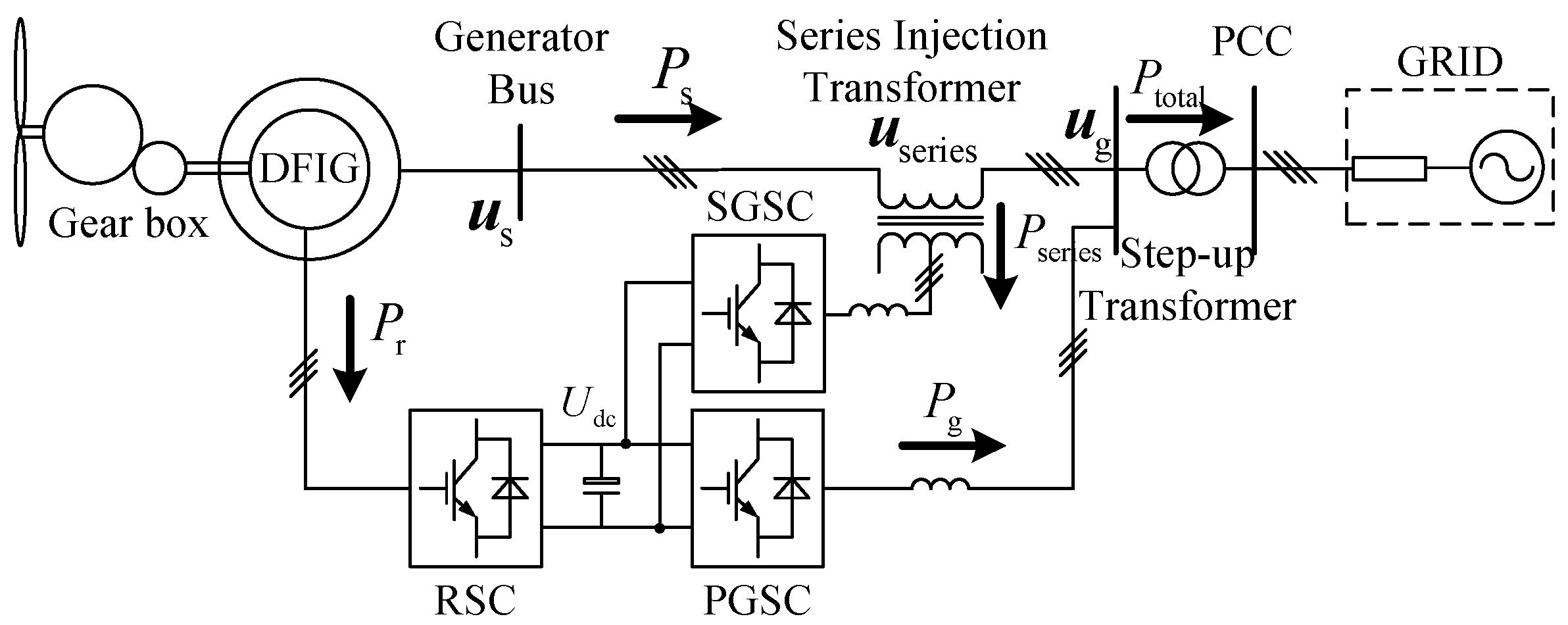
The main reason causing stator and rotor current distortions, electromagnetic torque and power pulsations in the DFIG is harmonically distorted stator voltages, so if the stator voltage harmonics can be eliminated and only the positive-sequence voltage is left, the adverse effects of network voltage distortion upon the DFIG will be removed naturally. As similarly discussed in [
20,
21,
22], the DFIG system with a series grid-side converter (SGSC) can be used to enhance the overall operation performance under distorted voltage conditions. As mentioned in [
20,
21,
22], by coordinately controlling the SGSC, PGSC and RSC, the DFIG system with SGSC has been fully demonstrated to be able to deal with the LVRT operation under severely symmetrical and unsymmetrical grid faults or network unbalance in steady-state operation. However, the operation and control of such a DFIG system under grid voltage harmonic distortion have not been discussed in detail. Unlike other series voltage compensation methods using a DVR mentioned in [
15,
16,
17,
18,
19], the DFIG system with SGSC can also cope with the case of steady-state grid voltage harmonic distortions as the SGSC is directly connected with the PGSC and RSC through the dc-link.
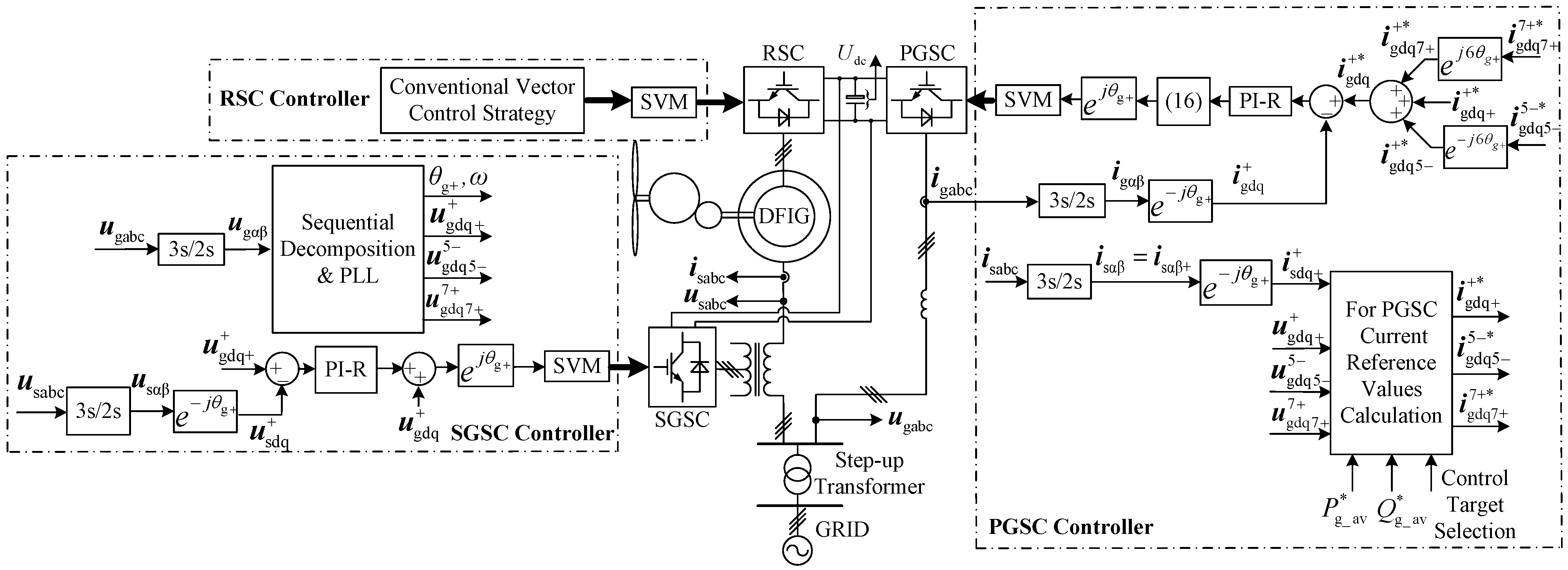
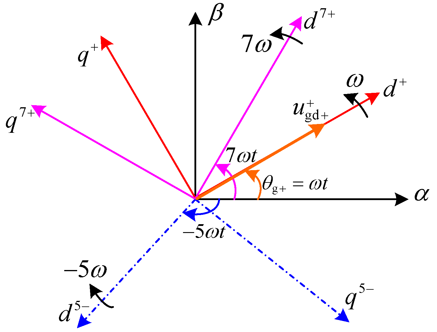
For the operation and control of SGSC, PGSC and RSC during network harmonic distortions, this paper investigates ways to further improve the operation performance of the DFIG system with SGSC. In the grid voltage-oriented positive (dq)+ and harmonic (dq)5−, (dq)7+ reference frames, the mathematical models of SGSC and PGSC under 5th and 7th grid voltage harmonics are developed. Besides, the control target for the SGSC and different control targets for the PGSC under the distorted voltage conditions are identified, and the reference values of the PGSC’s fundamental and harmonic currents are deduced. Furthermore, a coordinated control of the SGSC, PGSC and RSC and control schemes for SGSC and PGSC using a PI controller and a harmonic resonant regulator tuned at six times the grid frequency in the positive (dq)+ reference frame are developed. Finally, numerical simulations on a 2 MW DFIG system with SGSC are presented to verify the proposed control scheme.
4. Evaluation Studies
For evaluation of the proposed control strategy, simulations on a 2 MW DFIG-based wind power generation system with SGSC have been conducted by using Matlab/Simulink. Details of the simulated DFIG system are given in the
Appendix A. The PI-R controller parameters for both SGSC voltage and PGSC current by using the traditional transfer function design method are listed in
Table 1.
Table 1.
Parameters of the PI-R controllers.
Table 1.
Parameters of the PI-R controllers.
| Converter | Kp | Ki | Kr | ωc (rad/s) |
|---|
| PGSC | 10 | 200 | 200 | 5 |
| SGSC | 10 | 200 | 200 | 5 |
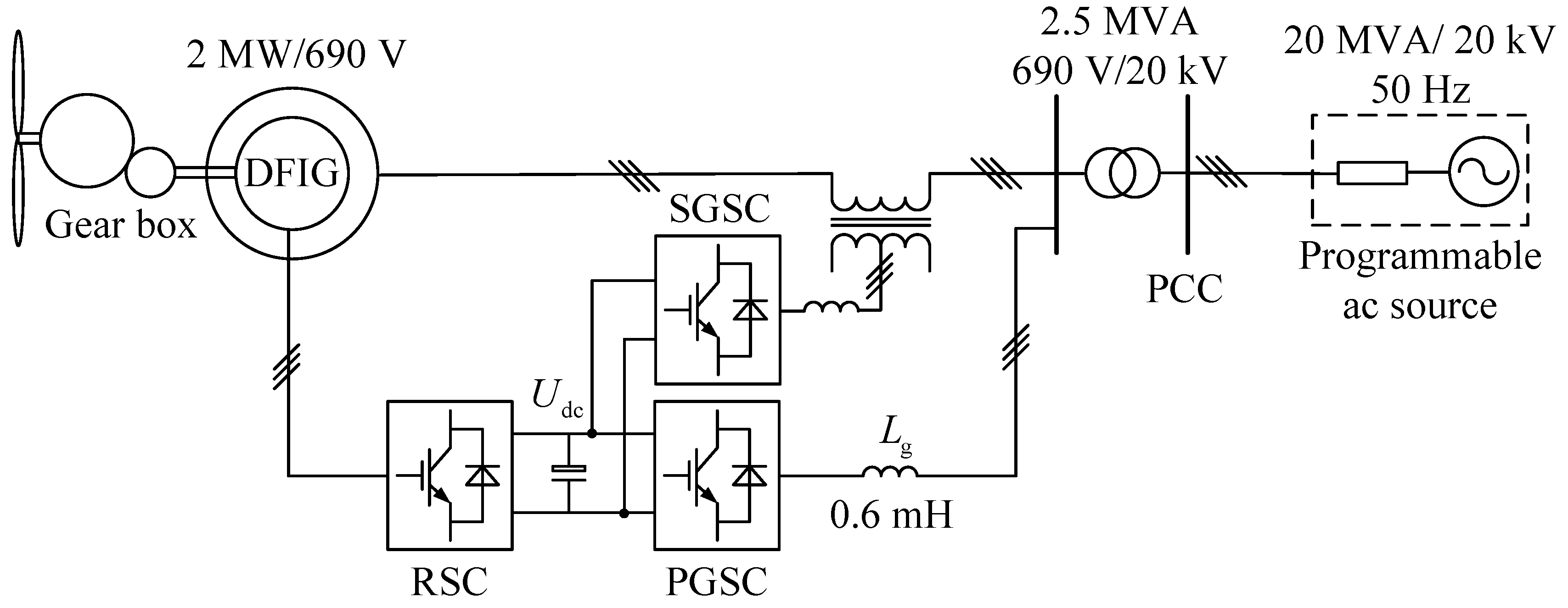
Figure 4 shows the configuration of the simulated DFIG system with SGSC. In the simulation model, three discrete control systems are built for the SGSC, PGSC and RSC, respectively. The DFIG is rated at 2 MW/690 V, and the dc-link voltage is set at 1200 V. The discrete control periods for the three converters are all 100 μs, and the switching frequency for each converter is 2 kHz. The DFIG system is connected to a programmable power grid rated at 20 MVA via a step-up transformer. The programmable ac voltage source is used to generate the fifth- and seventh-order harmonic grid voltages during the simulation studies, which are set to 4% and 3%, respectively. During the initial simulation, the rotor speed is assumed to be fixed at a normal speed of 1950 r/min (the maximal slip: –0.3). The total active and reactive power outputs of the generation system are 2 MW and zero (rated power and unit power factor), respectively.
Figure 4.
Configuration of the simulated DFIG system with SGSC.
Figure 4.
Configuration of the simulated DFIG system with SGSC.
Figure 5,
Figure 6 and
Figure 7 show the simulation results of the DFIG system with SGSC under grid voltage harmonics of the aforementioned condition between 1.6 and 1.7 s.
Figure 5 shows the simulation results of the system with the conventional control strategy,
i.e., no harmonic control for the system during grid voltage harmonics, while the
Figure 6 and
Figure 7 show the simulation results of the system with the proposed control Targets 1 and 2, respectively. During the simulation process, the RSC is controlled with the conventional vector control strategy to achieve the decoupling control of stator active and reactive powers, while the SGSC is controlled to keep the DFIG stator voltage always in line with the positive-sequence grid voltage and the PGSC is controlled with two different control targets.
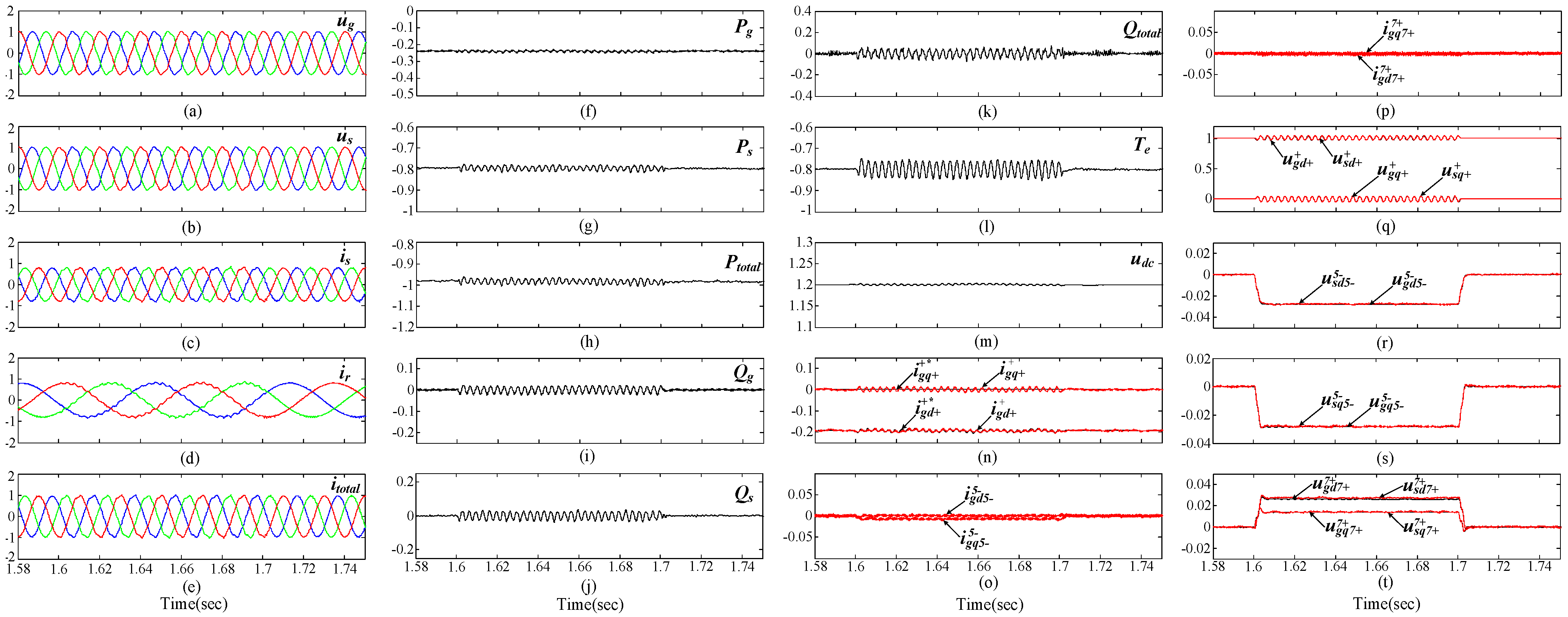
Figure 5.
Simulation results of DFIG system with SGSC under distorted grid voltage condition between 1.6 and 1.7 s without harmonic control. (a) grid voltage (pu); (b) stator voltage (pu); (c) stator current (pu); (d) rotor current (pu); (e) total current (pu); (f) PGSC active power (pu); (g) stator active power (pu); (h) total active power (pu); (i) PGSC reactive power (pu); (j) stator reactive power (pu); (k) total reactive power (pu); (l) electromagnetic torque (pu); (m) common dc-link voltage (V); (n) PGSC positive-sequence dq-axis currents reference and response (pu); (o) PGSC 5th harmonic dq-axis currents (pu); (p) PGSC 7th harmonic dq-axis currents (pu); (q) grid and stator positive-sequence dq-axis voltages (pu); (r) grid and stator 5th harmonic d-axis voltages (pu); (s) grid and stator 5th harmonic q-axis voltages (pu); (t) grid and stator 7th harmonic dq-axis voltages (pu).
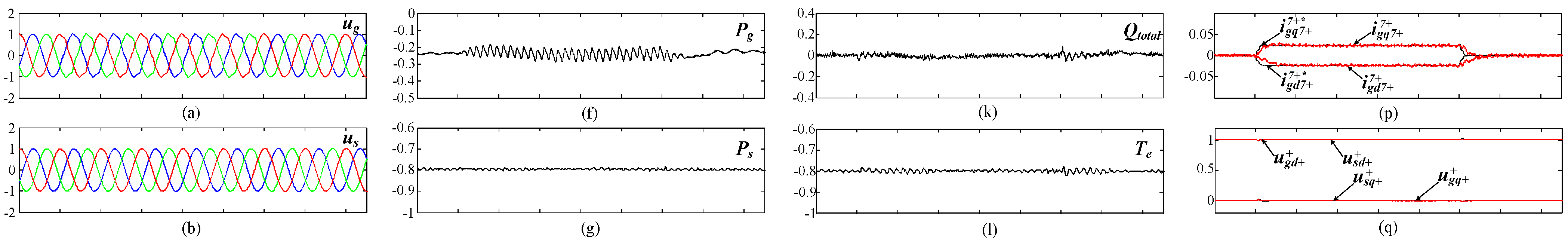
Figure 6.
Simulation results of DFIG system with SGSC under distorted grid voltage condition between 1.6 and 1.7 s with proposed control scheme with Target 1. (a) grid voltage (pu); (b) stator voltage (pu); (c) stator current (pu); (d) rotor current (pu); (e) total current (pu); (f) PGSC active power (pu); (g) stator active power (pu); (h) total active power (pu); (i) PGSC reactive power (pu); (j) stator reactive power (pu); (k) total reactive power (pu); (l) electromagnetic torque (pu); (m) common dc-link voltage (V); (n) PGSC positive-sequence dq-axis currents reference and response (pu); (o) PGSC 5th harmonic dq-axis currents reference and response (pu); (p) PGSC 7th harmonic dq-axis currents reference and response (pu); (q) grid and stator positive-sequence dq-axis voltages (pu); (r) grid and stator 5th harmonic d-axis voltages (pu); (s) grid and stator 5th harmonic q-axis voltages (pu); (t) grid and stator 7th harmonic dq-axis voltages (pu).
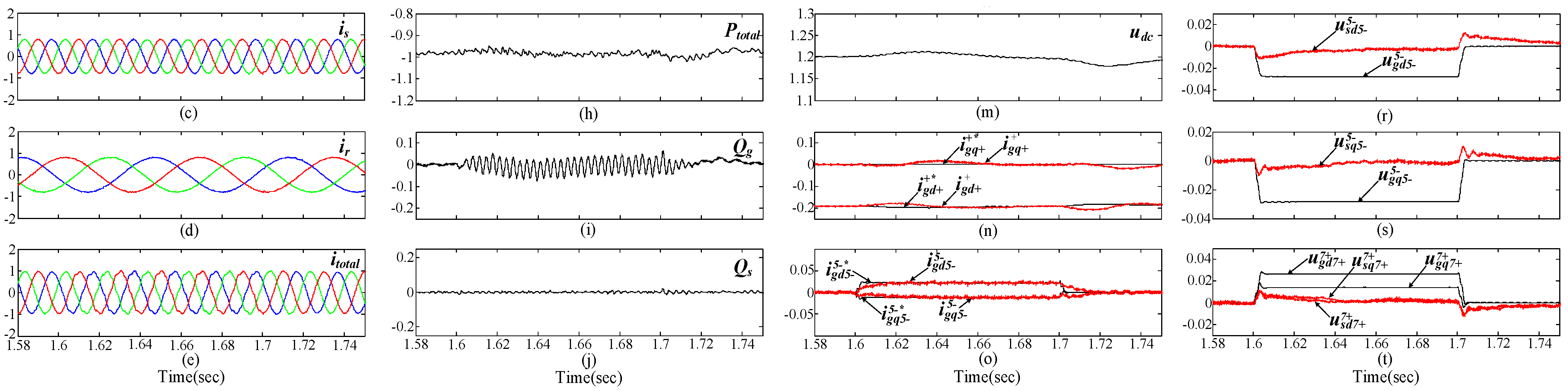
Figure 7.
Simulation results of DFIG system with SGSC under distorted grid voltage condition between 1.6 and 1.7 s with Proposed control scheme with Target 2. (a) grid voltage (pu); (b) stator voltage (pu); (c) stator current (pu); (d) rotor current (pu); (e) total current (pu); (f) PGSC active power (pu); (g) stator active power (pu); (h) total active power (pu); (i) PGSC reactive power (pu); (j) stator reactive power (pu); (k) total reactive power (pu); (l) electromagnetic torque (pu); (m) common dc-link voltage (V); (n) PGSC positive-sequence dq-axis currents reference and response (pu); (o) PGSC 5th harmonic dq-axis currents reference and response (pu); (p) PGSC 7th harmonic dq-axis currents reference and response (pu); (q) grid and stator positive-sequence dq-axis voltages (pu); (r) grid and stator 5th harmonic d-axis voltages (pu); (s) grid and stator 5th harmonic q-axis voltages (pu); (t) grid and stator 7th harmonic dq-axis voltages (pu).
As it can be seen from
Figure 5,
Figure 6 and
Figure 7a, due to the existence of the fifth- and seventh-order harmonic grid voltage components, the grid voltages are obviously distorted between 1.6 and 1.7 s. In a conventional control system, a only single PI controller in the positive (dq)
+ synchronous reference frame is used for the SGSC voltage and PGSC current. As the traditional single PI controller of SGSC has limited regulating gain for the fifth- and seventh-order harmonic voltage components which are oscillating at six times the grid frequency in the positive (dq)
+ reference frame, the fifth- and seventh-order voltage harmonics in the stator still exist and the stator voltages will contain 300 Hz pulsations in the positive synchronous reference frame, as shown in
Figures 5b,q–t. The harmonically polluted stator voltages will lead to badly distorted stator currents, which inevitably make the rotor currents contain both fundamental component of 15 Hz, and harmonic components of 315 Hz (300 + 15 Hz) and 285 Hz (300 – 15 Hz), respectively. Consequently, the significant oscillations at 300 Hz in the electromagnetic torque and instantaneous stator powers of DFIG could occur, as shown in
Figure 5g,j,l. In the meanwhile, distorted currents and power pulsations in the PGSC will also result from the failure regulation of harmonic currents in the PGSC when a single current PI controller is used, which further degrading the operation performance of whole system, as shown in
Figure 5e,f,h,i,k,n. As it can be seen from
Figure 6 and
Figure 7b,q–t, when the proposed control strategy for the SGSC under distorted grid voltage condition is implemented, the harmonic voltage at the DFIG’s stator terminal can be eliminated by injecting appropriate series compensation voltages of SGSC to counteract the grid voltage harmonics, although the grid voltage harmonics always exist. Compared with the conventional control method, the fundamental component of the stator voltage is controlled to be equal to the positive-sequence grid voltage, while the harmonic components of the stator voltage are effectively controlled to zero by using the proposed PI-R voltage control strategy. As analyzed in
Section 2, once the stator voltage harmonics are suppressed, the stator and rotor current harmonics, electromagnetic torque and power oscillations in the DFIG will be eliminated naturally, which are nicely demonstrated in
Figure 6 and
Figure 7c,d,g,j,l.
The system performances with the two different control targets for the PGSC are compared in
Figure 6 and
Figure 7. As seen in these figures, the objectives of the two control targets have been fully achieved. With Target 1, the 300 Hz oscillations in the total active power and reactive power entering the power grid can be eliminated simultaneously, and the pulsation of the common dc-link voltage is also suppressed effectively, as shown in
Figure 6h,k,m. When Target 2 is selected, the fifth- and seventh-order harmonic currents of PGSC can be eliminated successfully, as analyzed in
Section 3, the total current distortions can also be suppressed, as shown in
Figure 7e. With the limited control variables of the PGSC, the oscillation of the total active and reactive power output could not be eliminated simultaneously, as shown in
Figures 7h,k, respectively.
Figure 5,
Figure 6 and
Figure 7 also show the system dynamic responses with the conventional standard PI control scheme and the developed PI-R control method when the voltage distortions occurring between 1.6 and 1.7 s, respectively. As shown, compared with the case without harmonic control, the required voltage and current references can be obtained with the improved control targets, which allow us to achieve the goal of eliminating 300 Hz pulsations in the total output powers entering the grid or removing fifth- and seventh-order harmonic currents injected to the grid. With the proposed PI-R controllers for the SGSC and PGSC, the respective fifth- and seventh-order harmonic voltages or currents oscillating at 300 Hz in the positive (dq)
+ reference frame can be tuned to the their references by using the resonance regulator. Consequently, it can be seen that the voltage and current feedback signals of SGSC and PGSC precisely track their corresponding reference values, which indicates that the developed PI-R controllers have excellent dynamic response performance. It is also worth noting that the function of SGSC does not need to be changed during the normal grid condition and the distorted voltage condition for the PGSC’s two control strategies, and the R regulator can eliminate the harmonic voltages or currents when the voltage distortions is cleared, which means that the developed PI-R regulator can work under both distorted grid voltage conditions and the normal conditions, without any modifications.
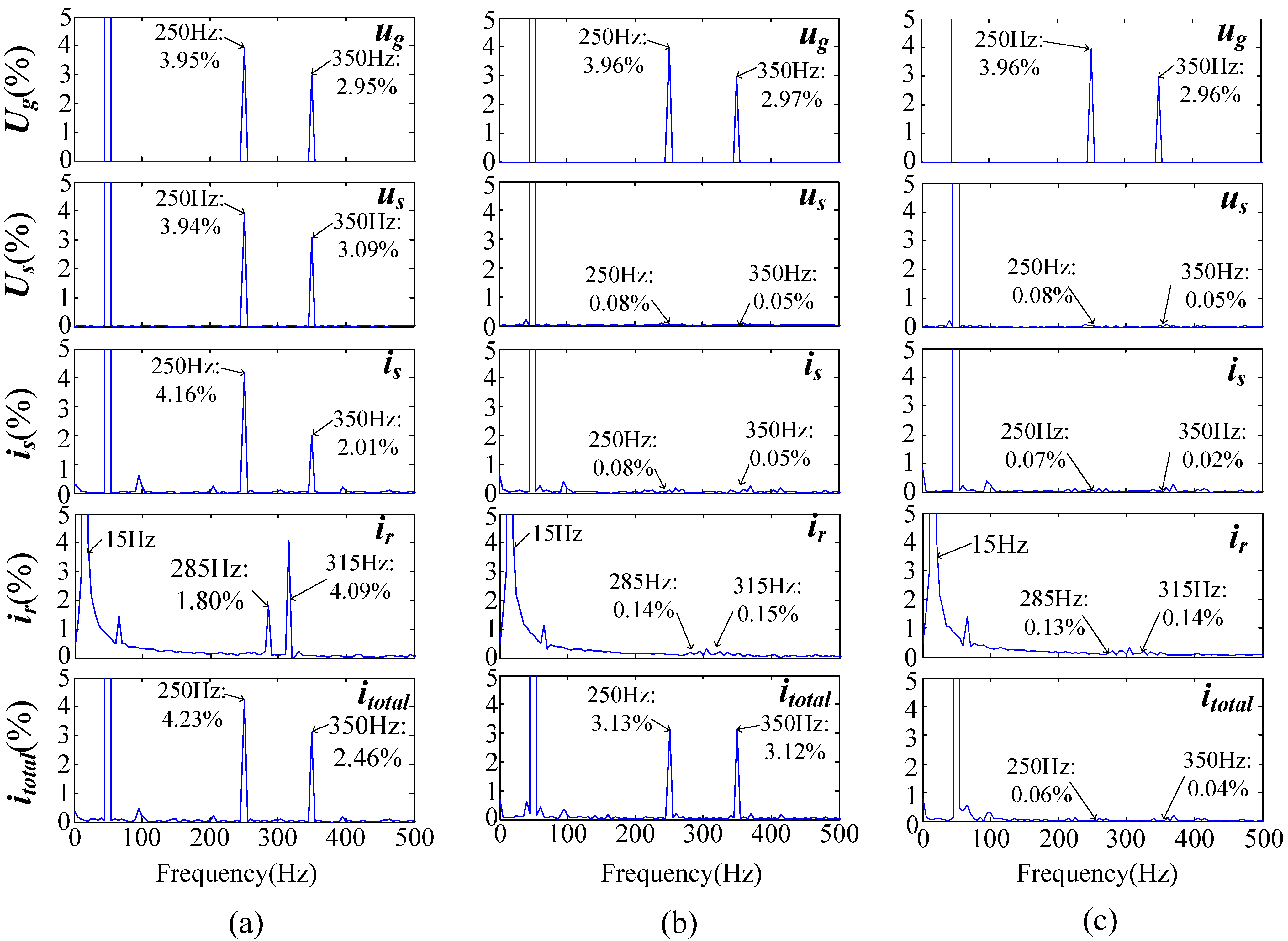
For detailed comparison, the harmonic spectrums of the grid and stator voltages, the stator and rotor currents are given in
Figure 8, and the harmonic and pulsating components are listed in
Table 2. As shown, the two control targets have been fully achieved with the proposed control strategies. With the effective control of SGSC, the fifth- and seventh-order voltage harmonics in the stator have been successfully suppressed, reduced to 0.08% and 0.05% with respect to the fundamental component, respectively. As a consequence, not only the stator and rotor current harmonics but also the significant oscillations in the DFIG’s electromagnetic torque and output powers can be avoided simultaneously, which undoubtedly improves the operation performance and stability of the generator under distorted network conditions. With Target 1, the 300 Hz pulsations in both the total active and reactive power entering the grid and dc-link voltage can be eliminated simultaneously. In addition, Target 2 can effectively diminish the total harmonic currents injected to the grid. While for a practical system, the control target can be flexibly selected by considering the operation of the network to meet different requirements.
Figure 8.
Harmonic spectrums. (a) No harmonic control; (b) Proposed control scheme with Target 1; (c) Proposed control scheme with Target 2.
Figure 8.
Harmonic spectrums. (a) No harmonic control; (b) Proposed control scheme with Target 1; (c) Proposed control scheme with Target 2.
Table 2.
Comparisons of different control Targets.
Table 2.
Comparisons of different control Targets.
| Measured Parameter | Conventional | Target 1 | Target 2 |
|---|
| us 5th harmonic (%) | 3.94% | 0.08% | 0.08% |
| us 7th harmonic (%) | 3.09% | 0.05% | 0.05% |
| is 5th harmonic (%) | 4.16% | 0.08% | 0.07% |
| is 7th harmonic (%) | 2.01% | 0.05% | 0.02% |
| ir 19th harmonic (%) | 1.80% | 0.14% | 0.13% |
| ir 21st harmonic (%) | 4.09% | 0.15% | 0.14% |
| itotal 5th harmonic (%) | 4.23% | 3.13% | 0.06% |
| itotal 7th harmonic (%) | 2.46% | 3.12% | 0.04% |
| Ps pulsation (pu) | 0.03 | 0.007 | 0.007 |
| Qs pulsation (pu) | 0.06 | 0.012 | 0.01 |
| Ptotal pulsation (pu) | 0.04 | 0.01 | 0.07 |
| Qtotal pulsation (pu) | 0.13 | 0.03 | 0.12 |
| Tem pulsation (pu) | 0.10 | 0.01 | 0.01 |
| udc pulsation (V) | 4.0 | 2.0 | 2.0 |
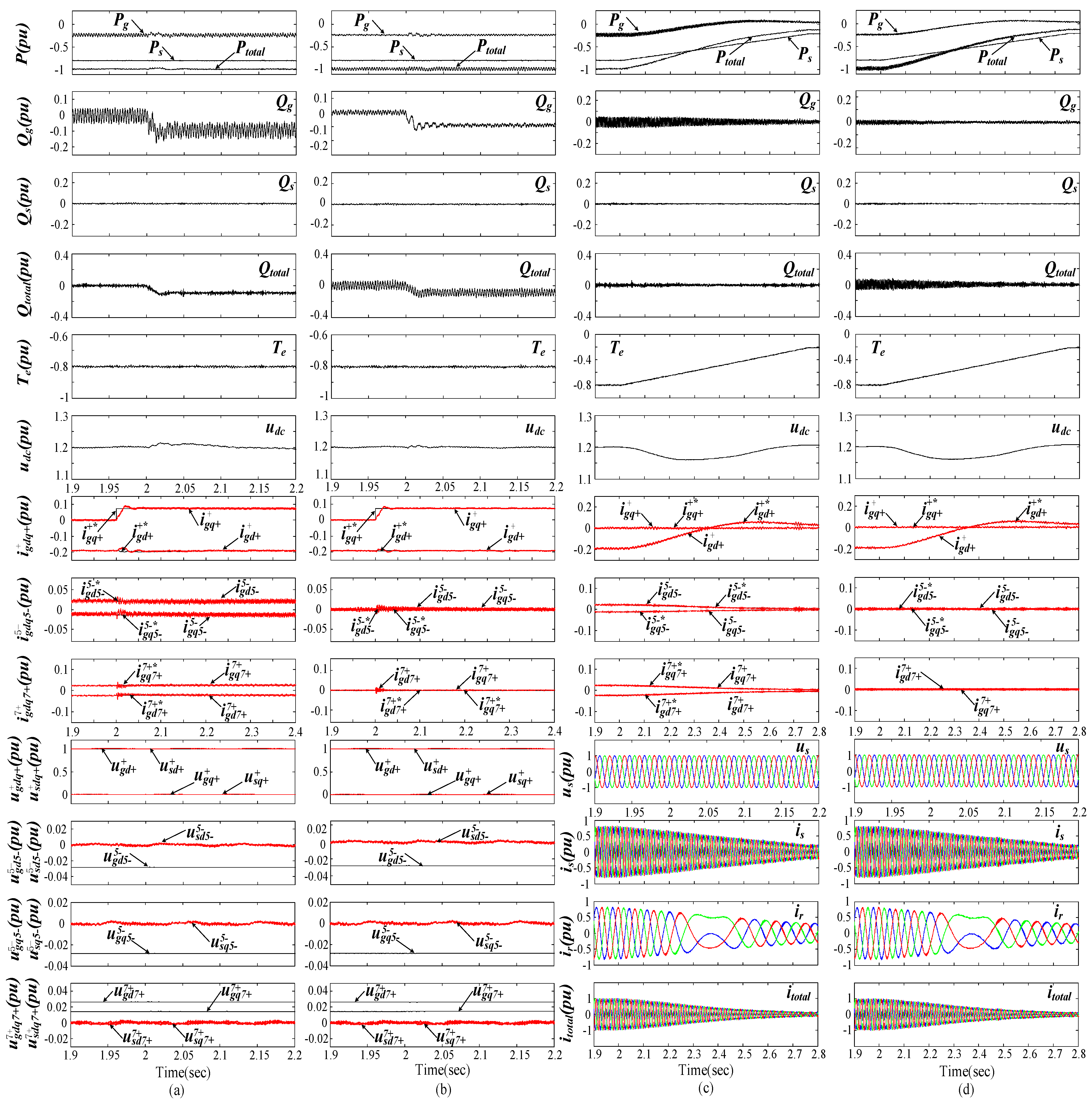
To further illustrate the robustness of the proposed control strategies, the system responses with both a step change of PGSC’s reactive power and the variations of generator’s speed and active power under 4% 5th and 3% 7th steady-state voltage condition are carried out.
Figure 9a,b show the results when a step change of PGSC’s reactive power from 0 to –0.1 pu at 2.0 s. As shown, the dynamic response of the PGSC’s reactive power is relatively satisfactory, which means that the PGSC can participate in the auxiliary reactive power regulation if needed. Meanwhile, the fifth- and seventh- order PGSC current harmonics can accurately track their reference values during the PGSC’s reactive power quick regulation, and the other operation requirements for the DFIG system can also be fully met with the two control targets. Simulations during variable rotor speed and power with the proposed control strategies are shown in
Figure 9c,d. During the simulation process, the generator speed is changed from 1.3 to 0.8 pu during 2.0 s to 2.7 s, and the stator active power is changed from –0.8 pu to –0.2 pu with the stator reactive power being zero. It is obvious that the operation performances of the DFIG system with the variations of rotor speed and power are nicely demonstrated. With the developed control strategies, the oscillations in electromagnetic torque, stator active and reactive powers, and total power outputs or total harmonic currents are eliminated during the whole process. In addition, the three phase stator and rotor currents of the DFIG are all sinusoidal and balanced as well. As the power pulsations in PGSC and SGSC are proportional to the stator current, as a consequence, the peak amplitude of oscillating active and reactive power in the PGSC and the DFIG system are all decreased with the reduction of the generator’s output power, as shown in
Figure 9c,d.
Figure 9.
Simulation results with PGSC’s reactive power step at 2.0 s and generator speed variations during 2.0 s to 2.7 s. (a) Reactive power step with Target 1; (b) Reactive power step with Target 2; (c) Variable rotor speed with Target 1; (d) Variable rotor speed with Target 2.
Figure 9.
Simulation results with PGSC’s reactive power step at 2.0 s and generator speed variations during 2.0 s to 2.7 s. (a) Reactive power step with Target 1; (b) Reactive power step with Target 2; (c) Variable rotor speed with Target 1; (d) Variable rotor speed with Target 2.
To further illustrate the robustness of the proposed control strategies, the system responses with both a step change of PGSC’s reactive power and the variations of generator’s speed and active power under 4% 5th and 3% 7th steady-state voltage condition are carried out.
Figure 9a,b show the results when a step change of PGSC’s reactive power from 0 to –0.1 pu at 2.0 s. As shown, the dynamic response of the PGSC’s reactive power is relatively satisfactory, which means that the PGSC can participate in the auxiliary reactive power regulation if needed. Meanwhile, the fifth- and seventh- order PGSC current harmonics can accurately track their reference values during the PGSC’s reactive power quick regulation, and the other operation requirements for the DFIG system can also be fully met with the two control targets. Simulations during variable rotor speed and power with the proposed control strategies are shown in
Figure 9c,d. During the simulation process, the generator speed is changed from 1.3 to 0.8 pu during 2.0 s to 2.7 s, and the stator active power is changed from –0.8 pu to –0.2 pu with the stator reactive power being zero. It is obvious that the operation performances of the DFIG system with the variations of rotor speed and power are nicely demonstrated. With the developed control strategies, the oscillations in electromagnetic torque, stator active and reactive powers, and total power outputs or total harmonic currents are eliminated during the whole process. In addition, the three phase stator and rotor currents of the DFIG are all sinusoidal and balanced as well. As the power pulsations in PGSC and SGSC are proportional to the stator current, as a consequence, the peak amplitude of oscillating active and reactive power in the PGSC and the DFIG system are all decreased with the reduction of the generator’s output power, as shown in
Figure 9c,d.


