Article

Development of Natural Gas Fired Combined Cycle Plant for Tri-Generation of Power, Cooling and Clean Water Using Waste Heat Recovery: Techno-Economic Analysis

1
Swiss Center for Electronics and Microtechnology, CSEM-UAE Innovation Center LLC, Al Jazeera-Al Hamra, PO Box 31208, Ras Al-Khaimah, UAE
2
Department of Energy Technology, KTH Royal Institute of Technology, Stockholm 10044, Sweden
*
Author to whom correspondence should be addressed.
Energies 2014, 7(10), 6358-6381; https://doi.org/10.3390/en7106358
Submission received: 30 June 2014 / Revised: 4 September 2014 / Accepted: 22 September 2014 / Published: 8 October 2014
(This article belongs to the Special Issue Waste Heat Recovery—Strategy and Practice)

Abstract

:
Tri-generation is one of the most efficient ways for maximizing the utilization of available energy. Utilization of waste heat (flue gases) liberated by the Al-Hamra gas turbine power plant is analyzed in this research work for simultaneous production of: (a) electricity by combining steam rankine cycle using heat recovery steam generator (HRSG); (b) clean water by air gap membrane distillation (AGMD) plant; and (c) cooling by single stage vapor absorption chiller (VAC). The flue gases liberated from the gas turbine power cycle is the prime source of energy for the tri-generation system. The heat recovered from condenser of steam cycle and excess heat available at the flue gases are utilized to drive cooling and desalination cycles which are optimized based on the cooling energy demands of the villas. Economic and environmental benefits of the tri-generation system in terms of cost savings and reduction in carbon emissions were analyzed. Energy efficiency of about 82%–85% is achieved by the tri-generation system compared to 50%–52% for combined cycles. Normalized carbon dioxide emission per MW·h is reduced by 51.5% by implementation of waste heat recovery tri-generation system. The tri-generation system has a payback period of 1.38 years with cumulative net present value of $66 million over the project life time.

Graphical Abstract

1. Introduction

Tri-generation is one of most promising technology integration practice for production of three different outputs with a common primary energy source. Combined heat and power cycle (CHP) would be transformed to poly-generation system by integrating heat driven cooling and desalination cycles in the system. Poly-generation cycles effectively utilize energy and reduce the greenhouse gas emission [1,2,3,4,5]. Combined cooling, heat and power (CCHP) is an extended version of CHP designed for centralized production of cooling, heating and power generation as a large scale system with higher efficiency [6]. In general, power plants in the Middle East and North Africa (MENA) region are combined with desalination plants for recovering heat and producing clean water for meeting domestic needs. However, since decentralized air conditioning systems in the region account for maximum power consumption, tri-generation models with combined production of cooling, clean water and power (CCCWP) would be more beneficial in terms of energy savings and economics.
Previously, several researchers investigated CCHP configurations with gas turbine, steam turbine and organic rankine cycles by combining with absorption, adsorption or desiccant chillers. Ahmadi et al. [7] conducted a detailed thermodynamic modeling of CCHP for providing cooling, hot water and electricity. The system is modeled with combined cycles of gas turbine and organic rankine cycle for power generation, single stage absorption chiller for cooling, and hot water through heat recovery. The system is analyzed in terms of energy efficiency and environmental impact, exergy efficiency of tri-generation system is improved by 20% compared to conventional CHP. Khaliq [8] simulated a gas turbine based tri-generation system for combined production of power, cooling and heat (process steam). Performance of the system is analyzed for different pressure ratios, turbine inlet temperatures, process heat pressures and evaporator temperatures of absorption chiller. Ahmadi et al. [9] conducted a detailed thermodynamic modeling and simulation of tri-generation system producing power through combined gas turbine and steam turbine cycles. The steam driven absorption chiller utilized to provide cooling, low pressure steam from the heat recovery steam generator (HRSG) is utilized as heat source for absorption chiller and space heating.
Several concepts for the tri-generation system involving reciprocating internal combustion (IC) engines for CCHP purposes were evolved for financial benefit. Temir and Bilge [10] studied the performance of tri-generation systems for production of electricity by reciprocating engines, absorption cooling using saturated steam from the boiler and process heat recovery from exhaust outlets. Huangfu et al. [5] analyzed the performance of micro-scale CCHP for domestic and light commercial applications using reciprocating internal combustion engines, absorption chiller and heat recovery devices. Energy and economic analysis reported a short payback period of 2.97 years. Sun [11] proposed a combined production cycle of electricity by gas engine and cooling by absorption chiller, which provides primary energy savings of 37% compared to separate conventional power and cooling systems with payback return in 4.52 years.
Tri-generation or poly-generation systems integrating the desalination technologies for clean water production is investigated by few researchers. Hussain [12] developed a tri-generation system for simultaneous production of cooling, clean water and electricity and analyzed with different technologies to provide cooling and clean water. The system is optimized based on its fuel saving potential. Out of different combinations analyzed, a combination of reverse osmosis, absorption chiller with gas turbine power cycle provides the highest economic benefits. Calise et al. [13] modeled a solar energy based tri-generation for CCCWP applications. Multi-effect desalination unit and vapor absorption chiller are integrated together with hybrid photovoltaic-thermal (PVT) collectors for combined production of cooling, desalination and power. The transient simulations for different operational and design parameters were conducted and optimized in terms of energetic efficiency and economic viability.
In this research work, combined cooling, clean water and power cycle (CCCWP) incorporated with membrane distillation technology for clean water production as a part of a tri-generation system is investigated. Membrane distillation is a promising thermal driven desalination technology, utilizing low grade heat energy for production of clean water [14]. Previously, research was conducted on integration of membrane distillation system for cogeneration applications. Liu [15] analyzed the performance of two different cogeneration systems by integrating membrane distillation modules with a gas engine as combined power and desalination cycles and with vapor compression chiller as a combined cooling and distillation unit. Kullab [16] analyzed the performance of air gap membrane distillation (AGMD) modules with different integration layouts. Burrieza et al. [17] conducted several parametric studies on air gap membrane distillation modules to optimize the performance of the system that produces a maximum distillate flux of 20 L/h per module.

2. System Description

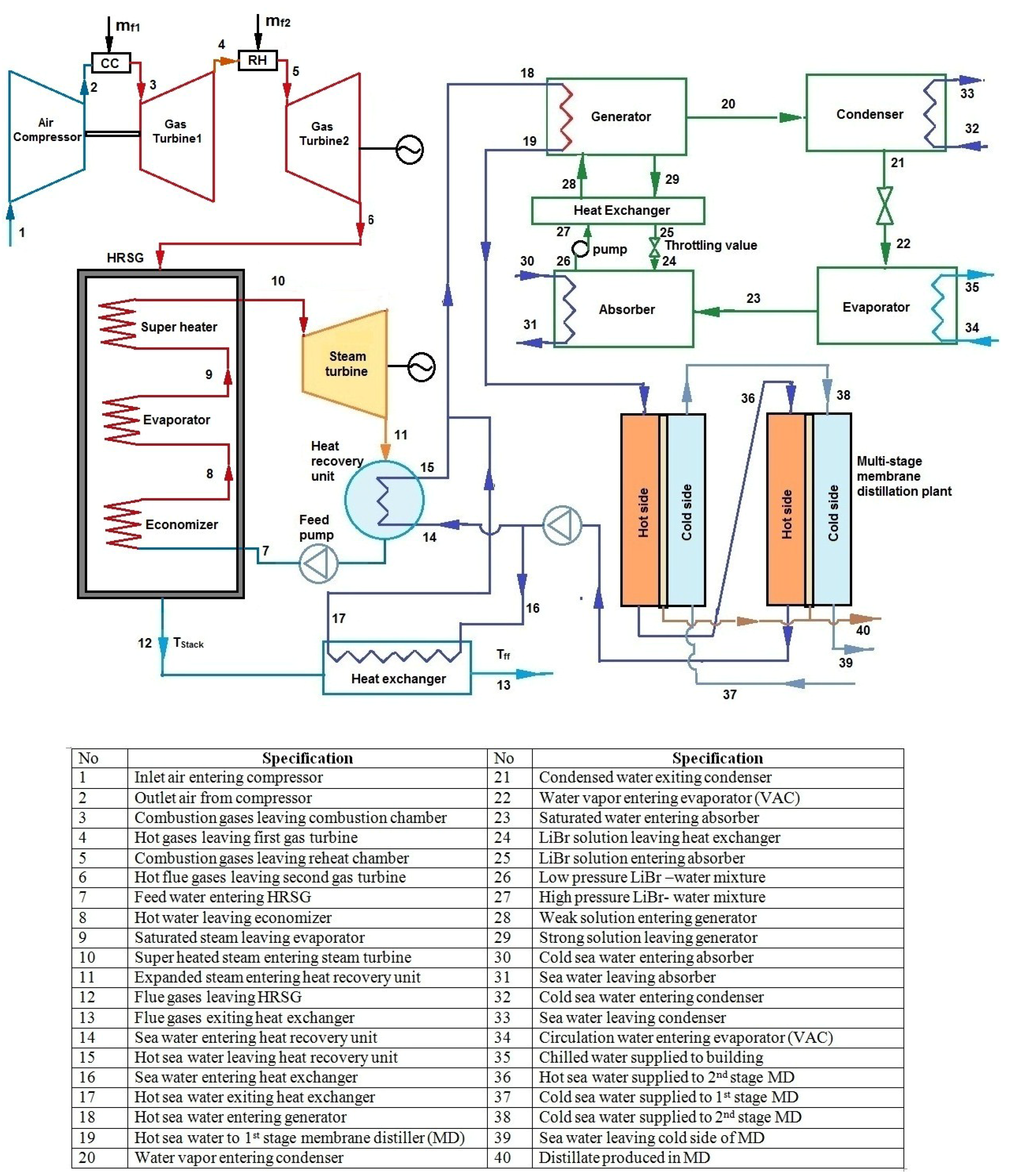
A tri-generation system is proposed for effective utilization of the waste flue gases liberated by the Al-Hamra gas turbine power plant based in Ras-Al-Khaimah, United Arab Emirates (UAE), as shown in Figure 1. Reheat brayton cycle configuration is utilized in Al-Hamra gas turbine power plant. Air at ambient temperature is compressed and passed to the combustion chamber (CC) for production of super-heated gas. This super-heated gas is further expanded in a series of gas turbines which are connected through reheat chamber (RH) for power production.
Figure 1. (a) Al-Hamra gas power plant; (b) Gas turbine in Al-Hamra power plant.
Energies 07 06358 g001
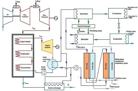
The proposed Tri-generation system comprises of steam turbine rankine cycle, single stage LiBr/H2O absorption chiller plant and air gap membrane distillation units. The schematic layout of tri-generation system is shown in Figure 2. The hot flue gases liberated after the expansion in the gas turbine is utilized in the HRSG for production of process steam at higher pressure and temperature, which is further expanded in a steam turbine for production of electricity. The steam is then condensed in a heat recovery system using sea-water. The heat liberated in the heat recovery system is used to drive both the absorption chiller and membrane distillation systems. The condensed steam (feed water) is circulated back to the HRSG using the feed water pump. The stack flue gases leaving the HRSG is utilized to produce additional hot sea water, which is integrated with the supply line of cooling and desalination systems.
Figure 2. Schematic layout of tri-generation system.
Energies 07 06358 g002

3. System Modeling

3.1. Brayton Cycle

The reheat Brayton configuration is utilized in Al-Hamra gas turbine power plant as shown in Figure 1. The energy balance of reheat brayton cycle is modeled as follows:
The air at ambient temperature enters the compressor at point 1, the temperature of air (T2) leaving the compressor is calculated by:
T 2 T 1 = ( P r 2 P r 1 ) γ 1 γ
where T1 and T2 are the temperatures of air entering and leaving the compressor; Pr1 and Pr2 are the pressures of air before and after compression process; γ is the specific heat ratio. Work done by the compressor is calculated by:
W Compressor = m ˙ a C p , air ( T 2 T 1 )
where WCompressor is the work done by the compressor; m ˙ a is the mass flow rate of air and Cp,air is the specific-heat capacity of air. The compressed air is supplied to the CC, where the compressed air is combusted with addition of fuel. Energy balance of processes in CC is given by:
Q CC = m ˙ g , 1 C p , gas , 1 T 3 m ˙ a C p , air T 2
Q CC = m ˙ f , 1 · L H V
where QCC is the heat energy supplied by the combustion chamber; m ˙ g , 1 is the mass of gas leaving the combustion chamber; T3 is the temperature of gas leaving the combustion chamber; m ˙ f , 1 is the mass flow rate of fuel supplied to CC and L H V is the lower heat-value of fuel. The gas at super-heated temperature (T3) is expanded in the first gas turbine,
Q gt , 1 = m ˙ g , 1 C p , gas ( T 3 T 4 )
where Qgt,1 is the energy extracted from the first gas turbine and T4 is the temperature of flue gases leaving the gas turbine. The flue gases liberated from the first gas turbine is further combusted in reheat chamber, energy balance in the reheat chamber is:
Q RH = m ˙ g , 2 C p , gas , 2 T 5 m ˙ g , 1 C p , gas , 1 T 4
Q RH = m ˙ f , 2 · L H V
QRH is the heat energy supplied by the reheat chamber; m ˙ g , 2 is the mass of gas leaving the reheat section; T5 is the temperature of gas leaving the reheat section and m ˙ f , 2 is the mass flow rate of fuel supplied to RH. The reheated gas is expanded in the second gas turbine:
Q gt , 2 = m ˙ g , 2 C p , gas , 2 ( T 5 T 6 )
where T6 is the temperature of flue gases leaving the system, which is utilized as the heat source for driving the tri-generation system.

3.2. Steam Cycle

3.2.1. Heat Recovery Steam Generator (HRSG)

In the tri-generation cycle, single pressure HRSG with economizer, evaporator and super heater sections are utilized for the generation of super-heated process steam. The temperature profile of HRSG is shown in Figure 3. The pinch point is the temperature difference between the gas and water (at saturation temperature) at the point of entry into the evaporator. Pinch point plays a vital role in energy modeling of HRSG. The approach temperature between the economizer exit and entry of evaporator is considered as constant in the modeling. Approach temperature depends on the tube layout of economizer circuit.
Figure 3. Temperature-Entropy (T-S) diagram of Heat Recovery Steam Generator (HRSG).
Energies 07 06358 g003
Energy balance of individual sections of HRSG is modeled. Using pinch point temperature difference, energy balance of the evaporator is analyzed:
m ˙ w ( h 9 h 8 ) = m ˙ g C P , g ( T a T b )
where m ˙ w is the mass flow rate of steam generation line; m ˙ g is the mass flow rate of hot flue gases; CP,g is the heat transfer coefficient of hot flue gases; h8’ and h9 are the enthalpy of the saturated water and steam, respectively; Ta is the temperature of gas entering the evaporator and Tb is the temperature of gas leaving the evaporator. Energy balance of the super heater is shown below:
m ˙ w ( h 10 h 9 ) = m ˙ g C P , g ( T 6 T a )
where h10 is the enthalpy of the super-heated steam and T6 is the temperature of hot flue gas entering the HRSG. Energy balance of the economizer can be shown as:
m ˙ w ( h 8 h 7 ) = m ˙ g C P , g ( T b T Stack )
where h7 and h8 are the enthalpies of the hot water at the entry and exit of economizer and TStack is the stack temperature of flue gases leaving the HRSG.

3.2.2. Steam Turbine

High pressure super-heated steam generated in the HRSG is expanded to ambient pressure using a steam turbine. Energy extracted (WST) in the turbine is calculated as follows:
W ST = m ˙ w ( h 9 h 10 )
where h10 is the enthalpy of steam leaving the turbine.

3.2.3. Heat Recovery System

The steam liberated from the steam turbine is condensed in a heat recovery system, where steam exchanges heat with sea water to drive both the absorption chiller and membrane distillation unit. Additionally, a part of heat energy is recovered by sea water from the stack flue gases. It is integrated with the supply line of refrigeration and desalination modules. Energy balance of the heat recovery system is given by:
Q extract = m ˙ w ( h 11 h 7 ) + m ˙ g C P , g ( T stack T ff )
Q extract = m ˙ SW C P , SW ( T SW , out T SW , in )
where Qextract is the heat extracted from the steam; h7 is the enthalpy of water leaving the condenser at 100 °C; Tff is the temperature of flue gas leaving the heat exchanger; m ˙ SW is the mass flow rate of sea water; CP,SW is specific heat capacities; TSW,in and TSW,out are the temperatures of sea water entering and leaving the heat recovery system. The area of heat recovery system is determined by:
A HRS = Q extract U HRS × Δ T LMTD
where AHRS is the area of the heat recovery system; UHRS is the overall heat transfer coefficient of the heat recovery system and Δ TLMTD is the logarithmic mean temperature difference.

3.3. Absorption Chiller

Absorption chiller considered in the tri-generation system is LiBr/H2O vapor absorption chiller. The system is designed to provide district cooling to multiple duplex-villas in the region of Al-Hamra, UAE as shown in Figure 4 [18]. The system is optimized based on cooling load requirements of villas. Energy balance of vapor absorption chiller is calculated as:
Q ch = m ˙ ac , ch C p Δ T ac , ch
Q gen = m ˙ SW C P , SW Δ T ac , h
C O P T = Q Ch Q gen
where Qch is the chilling capacity of absorption chiller; Qgen is the heat supplied the generator of absorption chiller; m ˙ ac , ch and m ˙ S W are the mass flow rates of chilled water and hot water flowing through the absorption chiller; Δ Tac,ch is the temperature difference of inlet and outlet of chilled-water circuit and Δ Tac,h is the temperature difference between hot water inlet and outlet of the generator.
Figure 4. Duplex villa in Al hamra.
Energies 07 06358 g004

3.4. Membrane Distillation

In the tri-generation system, membrane distillation module with air-gap configuration is considered for clean water production. The membrane modules considered for the analysis is manufactured by Scarab Development AB, Stockholm, Sweden. The hot sea water leaving the generator of the absorption chiller is supplied to a large number of multi-effect membrane distillation modules connected in parallel. Technical specifications of membrane distillation module are shown in Table 1.
Table 1. Technical specifications of membrane module [16]. Copyright 2011 KTH Royal Institute of Technology.
No.SpecificationValue
1Membrane area2.8 m2
2Porosity (ф)0.8
3Membrane thickness (b)0.2 mm
4Air gap width (L)1 mm
5Height of the module730 mm
6Width of the module630 mm
7Thickness of the module175 mm
The mass and energy balance of membrane modules are calculated based on experimental equations developed through series of experiments conducted in Nyköping, Sweden [15]. The mass flow rate of sea water supplied to hot and cold side is optimally selected as 1200 kg/h based on detailed experimental campaign [15]. The experimental equations for mass and energy flux are derived in function of porosity, air gap thickness, membrane thickness and inlet temperatures of hot and cold fluids. These equations provide better approximations [15,16].
M dis = 4.1 × 10 3 × 1 [ b / ( ϕ × T MD , H , in ) ] + ( L / T MD , C , in ) × ln ( 1 X c ) ( 1 X h )
where Mdis is the mass of distillate produced per hour for unit surface area of the membrane; b is the thickness of the membrane; L is the air gap distance; Xc and Xh are the mole fraction of water vapor on at the condensation and evaporation surfaces; TMD,H,in, TMD,H,out, TMD,C,in and TMD,C,out are the temperature of hot water inlet, hot water outlet, cold water inlet and cold water outlet of the AGMD:
X c = p i , c P
X h = p i , h P
p i , c = e ( 12.03 4025 T MD , C , in + 235 )
p i , h = e ( 12.03 4025 T MD , H , in + 235 )
where pi,h and pi,c are the partial pressures of the vapor at hot and cold sides; P is the total pressure, Energy flux (EMD) of the AGMD is calculated by:
E MD = 1.5 × 10 3 × ( T MD , H , in T MD , C , in ) ( b / ( γ ϕ T M D , H , i n ) ) + ( L / T M D , C , i n ) × ( 1 + 1.41 × ln   ( 1 X c ) ( 1 X h ) ) × b / ( γ ϕ T MD , H , in ) ( b / ϕ T MD , H , in ) + ( L / T MD , C , in )
γ = k membrane ϕ × k air
ϕ is the porosity of the membrane material; kair is the thermal conductivity of air; kmembrane is based on material type. The useful energy consumed by the membrane distillation is calculated as:
Q dis = M dis   ( λ L )
where Qdis is the useful energy required for evaporation of vapor; λL is the latent heat of evaporation.

3.5. Energy Efficiency

Energy efficiency is the ratio of useful energy produced by the system to the amount of energy supplied to the system. In this study, efficiency of gas turbine power plant (existing), combined cycle and tri-generation (power, cooling and desalination) are individually analyzed:
η GT = W GT m ˙ f × LHV
η C C = W GT + W ST m ˙ f × LHV
η Tri = W GT + W ST + Q ch + Q dis m ˙ f × LHV
where WGT and WST are the work done by the gas turbine and steam turbine; m ˙ f is the mass flow rate of the fuel; LHV is the lower heating value; Qch is the chilled energy produced in the absorption chiller and Qdis is the useful energy utilized by membrane distillation unit.

4. Results and Discussion

Thermodynamic modeling and optimization of complete tri-generation system for cooling, desalination and hot water is analyzed and discussed in this section.

4.1. Brayton Cycle

The gas turbine cycle is numerically modeled with data and parameters provided by the Al-Hamra gas turbine power plant [19]. The reheat-brayton cycle operated in the Al-Hamra power plant is optimized to maintain a constant temperature of 1097 K, at the inlet conditions of both the gas turbines irrespective of the air intake temperature. The pressure ratio and the rate of air intake at the compressor as well as the rate of fuel intake in the combustion and reheat chambers were optimized to achieve 1097 K at the inlet of gas turbines. The mean operational parameters of gas turbine are shown in Table 2. The performance of brayton cycle is analyzed for varying the air inlet temperatures as shown in Figure 5.
Table 2. Technical specifications of gas turbine power plant.
DescriptionParameters
Gas turbine model (GE-manufacturer)Model: LM2500 PE, Avio, Italy
Gas turbine inlet temperature824 °C
Mean intake air temperature 35 °C
Mean exhaust gas flow64.1 kg/s
Mean exhaust gas temperature550 °C
Lower Heating Value47,000 kJ/kg
Figure 5. Performance of gas power cycle for varying inlet temperatures.
Energies 07 06358 g005
The air intake temperature is an influential factor in augmenting the performance of gas turbine cycle. Reduction in the air intake temperature can drastically increase the gas turbine power output. However, on the contrary, reduction in air intake temperature increases the rate of fuel consumption in order to provide the desired operating temperature at the inlet of gas turbine. The mass of fuel consumption is derived based on the energy balances at the combustion and reheat chambers. Increase in fuel consumption has direct impact on the exhaust gas flow rate. The temperature of flue gases liberated from the gas turbine rises with the increase in air intake temperature. This results in reduction of pressures ratios with increase in air intake temperature to provide designed gas turbine inlet temperature.
The annual performance of the gas cycle in term of electricity generation and mass of fuel consumption is shown in Figure 6. As discussed earlier, the air inlet temperature is the influential parameter in the performance of the gas cycle. The electrical performance of the gas cycle reduces by 10% in peak summer months. Maximum productivity of 34 MW is achieved in winter months. Annual variations in the amount of flue gases produced and its temperatures are shown in Figure 6. In summer, the temperature of flue gases maximizes as the pressure ratio is reduced at higher air intake temperatures. The mass flow rate of exhaust gases liberated from the gas cycle is reduced in summer due to reduction in the amount of fuel consumption and rate of air intake.
Figure 6. Annual variations in power production, rate of fuel intake and exhaust gas parameters in gas cycle.
Energies 07 06358 g006

4.2. Steam Cycle

In HRSG, outlet conditions of the super-heated steam are optimized based on maximum permissible temperature and pressure ranges of the steam turbine. HRSG system is simulated for different inlet conditions of flue gases at feed pressure of 65 bar. Feed water flow rates are optimized for secure operation of steam cycle. Limiting the temperature of super-heated steam below the maximum acceptable temperature limit of the steam turbine is considered as the optimization criterion. Maintaining constant feed water flow rate in the steam cycle allows uniform heat recovery to drive cooling and desalination cycles throughout the year. Q-T profile of HRSG for the design conditions in the month of July is shown in Figure 7. HRSG is simulated with a constant approach temperature and pinch point difference of 10 K. Steam turbine is selected based on design conditions and requirements. The parameters of the steam turbine are shown in Table 3.
Figure 7. Q-T profile of HRSG in July.
Energies 07 06358 g007
Table 3. Technical specifications of steam turbine [20] (Copyright 2014 Siemens AG).
No.DescriptionParameters
1Steam turbine model (Siemens)SST-100
2Power output8.5 MW
3Inlet steam pressureUp to 65 bar
4Inlet steam temperatureUp to 480 °C
5Condensing pressure1 bar
6Exhaust area0.22 m2
The performance of the steam cycle in the tri-generation system is analyzed for the variations of air intake temperatures. The system is simulated for different inlet conditions of flue gases as shown in Figure 8a. The electricity production and stack temperature of flue gases leaving the HRSG are chosen as the prime indicative parameters in this study. The electricity production in steam power cycle follows a similar trend as the gas power cycle. Reduction in the quantity of flue gases at higher air intake temperature is the major influencing factor for the decreasing trend of power production. Energy balance in the economizer indicates that the stack temperature decreases with reduction in the mass-flow rate of flue gases. Annual performance of steam cycle is shown in Figure 8b. The performance of the steam cycle improves during winter months due to higher mass-flow rate of flue gases.
Figure 8. (a) Performance of steam power cycle for varying inlet temperatures; (b) Annual performance of steam cycle.
Energies 07 06358 g008

4.3. Absorption Chiller

In the district cooling network, duplex houses in the Al-Hamra region are considered. Duplex houses are two identical houses sharing a common wall with a total floor area of 390 m2 (195 m2 for single house). The cooling load requirement of a duplex house binding the ASHRAE standards is estimated by modeling and simulating the duplex house in TRNBuilt software. The annual cooling load distribution (hourly distribution) for maintaining indoor set point temperature of 22 °C is shown in Figure 9. The building simulation is conducted with occupancy of five persons per building and infiltration rate of 0.25 ACH. The enlarged peak cooling requirement of a duplex building is shown in Figure 9. Cooling energy requirements in the summer reach up to 36.5 kW for a duplex house, this peak cooling requirement is considered as the design condition for the distribution in the district cooling network. The coefficient of performance (COP) of the chiller varies between 0.75 and 0.69, as the system is operated with a hot water inlet temperature of 90 °C. The variation in COP is mainly due to the temperature of cold water supplied to the condenser.
Based on the energy balances of the heat recovery system, the total hot sea water production rate is determined to be 358 kg/s. This can be used to determine the chilling capacity of the absorption chiller. As discussed earlier, the peak load requirement is considered as the design parameter for sizing the distribution network. Performance of the absorption chiller plant during the peak load period with varying inlet hot water temperatures is shown in Figure 10a. The chilled energy production of the absorption chiller maximizes at higher temperatures. At the supply temperature of 90 °C, 4621.69 kW of chilled energy is produced. It is sufficient to meet the cooling demands of 124 duplex villas as the peak cooling demand per villa is 36.5 kW with a COP of 0.69. Reduction in the inlet hot water temperature by 10 °C affects the performance of chiller by 39%; steep decrease in performance of absorption chiller is observed with reduction in supply temperature. Operation of the absorption chiller is optimized based on the cooling demand requirements of the building. Month-wise cooling energy production by the absorption chiller is shown in Figure 10b. The production maximizes in the month of July as it corresponds to the cooling energy peak demand.
Figure 9. Annual cooling load in a duplex house.
Energies 07 06358 g009
Figure 10. (a) Performance of absorption chiller with varying inlet hot temperature; (b) Month-wise cooling energy production.
Energies 07 06358 g010

4.4. Membrane Distillation

Performance of two-stage membrane distillation system is evaluated by varying the temperatures of hot and cold sides as shown in Figure 10. The system is simulated for hot side temperatures from 60–90 °C and cold side temperatures between 10 °C and 50 °C with an increment of 5 °C as shown in Figure 11. The distillate productivity improves with increase in hot side temperature and decrease in cold side temperature. Maximum distillate productivity of a two-stage system is 41 kg/h with hot side temperature of 90 °C and cold side temperature of 10 °C.
Figure 11. Distillate production for variation in hot and cold side temperatures.
Energies 07 06358 g011
Based on the energy balance in the heat recovery system, a total of 967 multi-effect membrane desalination units can be connected in parallel, each unit containing two membrane modules connected in series. The thermal energy supplied to the membrane distillation plant is optimized based on cooling energy requirements. Year-round dynamic simulation of two-stage membrane distillation plant is conducted, productivity is affected by the cold side temperature and cooling energy demands as shown in Figure 12 and Figure 13. Sea water at ambient temperature is supplied to the cold side of the membrane distillation system. The productivity of desalination plant reduces gradually with increase in cooling energy demand and ambient temperature. Productivity of the plant drops by 12% in the summer due to higher cooling energy demands and cold side temperatures.
Figure 12. Effect of ambient temperature on distillate production.
Energies 07 06358 g012
Figure 13. Effect of cooling load on distillate production.
Energies 07 06358 g013

4.5. Energy Efficiency

Month-wise energy distribution between different thermal cycles of the tri-generation system is shown in Figure 14a. Useful energy produced by the tri-generation cycle is reduced in the summer months due to higher air intake temperature in the gas cycle leading to lesser fuel consumption. Month-wise energy efficiencies of gas cycle, combined cycle and tri-generation cycle is shown in Figure 14b. The gas cycle efficiency and combined cycle efficiency reduces in summer months due to lower power production, while the efficiency of tri-generation cycle increases by 4% during this period due to full scale operation of absorption chiller plant as shown in Figure 14b.
Figure 14. (a) Month-wise energy distribution; (b) Annual distribution of cycle efficiencies.
Energies 07 06358 g014
Energy flows during peak load conditions is represented in sankey diagram as shown in Figure 15. About 25% of waste heat could not be recovered due to sulfur condensation issues, major part of waste heat is been utilized for production of the fresh water.
Figure 15. Sankey diagram of energy flows.
Energies 07 06358 g015

4.6. Emission Analysis

Along with the energy benefits in terms of high thermal efficiencies, the tri-generation system also has the potential to reduce greenhouse gas emissions. Normalized emission of CO2 and NOx per MW·h is reduced by implementing poly-generation cycles. Variations of emissions for all three cycles—gas cycle, combined power cycle and tri-generation cycle—are shown in Figure 16. The CO2 coefficient emission per kW·h of electricity production is utilized for determining annual CO2 emissions. CO2 emission coefficient for UAE is 600 g of CO2 per kW·h of electricity production [21]. Normalized CO2 emission of tri-generation system reduces by 51.5%, which proves the environmental sustainability of the system. This reduction in normalized CO2 emission is achieved through total CO2 avoided by driving the tri-generation system using waste heat recovery. In tri-generation scenario, production has been increased by 51.5% with same amount of fuel usage leading to lower carbon emission. Along with CO2, other GHG emissions like NOx, SOx emissions were also reduced by 51.5%. In UAE, NOx contribute to 5% of total GHG emissions which leads to normalized production of 38 g per kW·h [22]. With tri-generation, the NOx emissions are reduced to 18.4 g per kW·h. Total CO2 and NOx emissions of the existing gas turbine power plant is estimated by:
T o t a l   e m i s s i o n s = e m i s s i o n   c o e f f i c i e n t × A n n u a l   e l e c t r i c i t y   p r o d u c t i o n
Figure 16. Normalized CO2 and NOx emissions.
Energies 07 06358 g016

4.7. Economic Analysis

Economic benefit of implementing the tri-generation system for the waste heat recovery is discussed in this section. Lower operating costs are achieved in the tri-generation system as waste heat is utilized in the complete operation. The cost of individual components and other necessary parameters are shown in Table 4. Total investment, operation and maintenance costs and annual benefits are estimated as shown in Table 5.
Table 4. Parameter and costs required for economic analysis.
ComponentAbbreviationValue
Heat recovery steam generator [23]CHRSGEquation (33)
Steam turbine [23]CSTEquation (37)
Heat recovery unit [24]CHRS$2,000/m2
Feed water pump (Steam cycle) [25]CST,PUMP881Wp0.4
Membrane distillation unit [26]CAGMD$1,375/unit
Membrane replacement cost [24]CMD,R15% of CAGMD
Feed pump (Heat recovery) [25]CHRS,PUMP881Wp0.4
Absorption chiller [27]CAC$400/kW
Hydraulics [26]CHYD5% of component costs
Installation cost [26]CI5% of component costs
Interest ratei10%
Life time of the project n20 years
Cost of electricityCF$0.12/kW·h
Table 5. Economic analysis of tri-generation system.
No.ParametersValues
1Investment cost$11,079,548
2Operating and maintenance cost$443,494
3Annual benefits$9,413,460
4Payback period1.38 years
5Net present value$66,102,281
The cumulative net present value (NPV) and payback period (PB) of the tri-generation system are evaluated and shown in Table 5. Annual benefits by implementing tri-generation are estimated based on total annual production of electricity, cooling and freshwater as shown in Table 6. The net present value for the project is estimated by:
N P V = C O + ( B C ) [ ( 1 + i ) n 1 i ( 1 + i ) n ]
where CO is the total investment cost; B is the annual benefits; C is annual operation and maintenance cost; i is the interest rate and n is the life time of the project. The payback period of the project is determined by:
P B = ln ( B C ) ln [ ( B C ) i C O ] ln ( 1 + i )
The investment of HRSG and steam turbine are determined by [23]:
C HRSG = 4131.8   ( f p . f T , steam . f T , gas ( Q Λ T ln ) 0.8 ) + 13380 ( f p . m ˙ steam ) + 1489.7 m ˙ gas 1.2
f p = 0.0971 P r 30   b a r + 0.9029
f T , steam = 1 + e x p ( T out , steam 830 500 )
f T , gas = 1 + e x p ( T out , gas 990 500 )
C ST = 3880.5 P ST 0.7 ( 1 + ( 0.05 1 η ST ) 3 ) . ( 1 + 5 e x p ( T in 866 10.52 ) )
where Q is the heat transfer in HRSG; Λ Tln is temperature difference across HRSG and Pr is the pressure of feed water to the HRSG. The total investment of cost (CO) of the project is calculated by:
C O = C HRSG ( P HRSG ) + C ST ( P ST ) + C HRS ( A HRS ) + C ST , PUMP ( P ST , PUMP ) + C AGMD ( N AGMD ) + C HRS , PUMP ( P HRS , PUMP ) + C AC ( P AC ) + C HYD
P HRSG , P ST , P ST , PUMP and P HR , PUMP are the total capacity of HRSG, steam turbine and feed pumps of the steam cycle and the heat recovery system. AHRS is the area of the heat recovery system and NAGMD is the number of membrane distillation modules. The annual operation and maintenance cost for tri-generation project includes electricity requirements for the feed pumps and membrane replacement charges.
Table 6. Annual benefits.
ParametersValueTotal benefits
Electricity production$0.12/kW·h$7,289,423.73
Cooling benefits$0.10/kW·h$1,582,854.46
Cooling demand charges$42.3/kW·year$211,500.00
Water production cost$1/m3$329,681.90
The share of different equipment costs involved in the total investment is shown in Figure 17. Investment costs of membrane distillation unit and steam turbine account for close to 46% of the total investment cost.
In terms of current fuel cost in the region, the system has a short payback of 1.38 years and greater cumulative profit of $66.10 million. Economic analysis with the possibility of changes in electricity prices is shown in Figure 18. The annual cash flows of the project are simulated with an interest rate of 10% as shown in Figure 19. The cash flow decreases with number of years as the present worth factor is considered.
Figure 17. Distribution of investment cost.
Energies 07 06358 g017
Figure 18. Economic analysis for tri-generation system.
Energies 07 06358 g018
Figure 19. Cash flows of tri-generation system.
Energies 07 06358 g019

5. Conclusions

A tri-generation system based on the integration of power, cooling and desalination thermal cycles was presented. A detailed numerical case study was developed for the implementation in Al-Hamra area, Ras Al Khaimah, UAE. The tri-generation system is modeled for maximizing the utilization of waste heat by driving four thermal cycles based on quality and temperature of thermal energy. The absorption chiller plant is optimized based on cooling energy requirement of duplex villas in the region. The simulation results show that energetic efficiency of tri-generation system is maximized by up to 85% in summer due to lower fuel consumption and full scale operation of absorption chiller. The thermal cycle performances are largely affected by air intake temperature, but due to the lower cooling requirement in winter, the overall thermal efficiency reduces with lower air intake temperatures. Other important conclusions drawn from the project of recovering waste heat from existing power plants are as follows:
  • The absorption chiller plant can provide district cooling for 124 duplex houses with a production capacity of 4600 kW during peak requirements;
  • The production capacity of membrane distillation plant varies between 33 and 37 m3/h based on daily cooling requirements and ambient temperature;
  • The normalized CO2 emission per MW·h is reduced to 291 kg/MW·h from an actual scenario of 600 kg/MW·h by implementation of the waste heat recovery system;
  • In terms of economy, the system has a rapid payback period of 1.38 years with a cumulative saving of $66 million.

Nomenclature

A
Area (m2)
AGMD
Air gap membrane distillation
B
Benefits ($)
CP
Specific heat capacity (kJ/kg·K)
CCHP
Combined cooling, heat and power
CHP
Combined heat and power cycle
E
Energy flux (kJ)
NPV
Net present value ($)
GHG
Greenhouse gases
K
Thermal conductivity (W/m·K)
LHV
Lower heating value
MENA
Middle East and North Africa
P
Power capacity (kW)
PB
Payback period (years)
Q
Heat energy (kJ)
S
Entropy (kJ/kg·K)
U
Overall heat transfer coefficient
X
Mole fraction of water vapor
ACH
Air changes per hour
B
Membrane thickness (mm)
C
Cost ($)
CC
Combustion chamber
CCCWP
Combined cooling, clean water and power
COP
Coefficient of performance
HRSG
Heat recovery steam generator
I
Interest rate (%)
H
Enthalpy (kJ/kg)
L
Air gap width (mm)
M
Mass flow (kg/h)
m ˙
mass flow rate (kg/s)
P
Partial pressure of vapor
Pr
Pressure (bar)
RH
Reheat chamber
T
Temperature (°C)
VAC
Vapor absorption chiller

Greek Letters

∆T
Change in temperature
λL
Latent heat of evaporation
Γ
Specific heat ratio
Ф
Porosity
Η
Efficiency

Subscripts

A
Air
C
Cold side
Ch
Chilled water
F
Fuel
Gen
Generator
H
Hot side
LMTD
Logarithmic mean temperature difference
RH
Reheat chamber
ST
Steam turbine
T
Thermal
Ac
Absorption chiller
Cc
Combustion chamber
Dis
Distillate
G
Gas
GT
Gas turbine
HRS
Heat recovery system
MD
Membrane distillation
Stack
Stack temperature
SW
Seawater
Tri
Tri-generation

Acknowledgments

The authors would like to extend their gratitude to the Ras Al Khaimah Investment Authority for their financial support and Al-Hamra gas turbine power plant for the technical cooperation. Special thanks to KTH Royal Institute of technology, Stockholm for the fruitful cooperation in the project.

Author Contributions

All the authors contributed in different ways during progress of the research work. Gowtham Mohan designed and simulated the waste heat recovery system with guidance of Sujata Dahal and Uday kumar. Sujata dahal developed the numerical codes for membrane distiller models. Andrew Martin verified the results and manuscript. Hamid kayal involved in verification of economics and managed the resources.

Conflicts of Interest

The authors declare no conflict of interest.

References

  1. Kong, X.Q.; Wang, R.Z.; Huang, X.H. Energy optimization model for a CCHP system with available gas turbines. Appl. Therm. Eng. 2005, 80, 377–391. [Google Scholar] [CrossRef]
  2. Khan, K.H.; Rasul, M.G.; Khan, M.M.K. Energy conservation in buildings: Cogeneration and cogeneration coupled with thermal-energy storage. Appl. Therm. Eng. 2004, 77, 15–34. [Google Scholar] [CrossRef]
  3. Havelsky, V. Energetic efficiency of cogeneration system for combined heat, cold and power production. Int. J. Refrig. 1999, 22, 479–485. [Google Scholar] [CrossRef]
  4. Bilgen, E. Exergetic and engineering analyses of gas turbine based cogeneration systems. Energy 2000, 25, 1215–1229. [Google Scholar] [CrossRef]
  5. Huangfu, Y.; Wu, J.Y.; Wang, R.Z.; Kong, X.Q.; Wei, B.H. Evaluation and analysis of novel micro-scale combined cooling, heating and power (MCCHP) system. Energy Convers. Manag. 2007, 48, 1703–1709. [Google Scholar] [CrossRef]
  6. Liu, M.; Shi, Y.; Fang, F. Combined cooling, heating and power systems: A survey. Renew. Sustain. Energy Rev. 2014, 35, 1–22. [Google Scholar] [CrossRef]
  7. Ahmadi, P.; Dincer, I.; Rosen, M.A. Exergo-environmental analysis of an integrated organic Rankine cycle for trigeneration. Energy Convers. Manag. 2012, 64, 447–453. [Google Scholar] [CrossRef]
  8. Khaliq, A. Exergy analysis of gas turbine trigeneration system for combined production of power heat and refrigeration. Int. J. Refrig. 2009, 32, 534–545. [Google Scholar] [CrossRef]
  9. Ahmadi, P.; Rosen, M.A.; Dincer, I. Greenhouse gas emission and exergo-environmental analyses of a trigeneration energy system. Int. J. Greenh. Gas Control 2011, 5, 1540–1549. [Google Scholar] [CrossRef]
  10. Temir, G.; Bilge, D. Thermoeconomic analysis of a trigeneration system. Appl. Therm. Eng. 2004, 24, 2689–2699. [Google Scholar] [CrossRef]
  11. Sun, Z.G. Energy efficiency and economic feasibility analysis of cogeneration system driven by gas engine. Energy Build. 2008, 40, 126–130. [Google Scholar] [CrossRef]
  12. Hussain, H.J. Development of a Hybrid Powerplant for Kuwait: The Simultaneous Production of Power, Fresh Water and Cooling. Ph.D. Thesis, Cranfield University, Shrivenham, UK, 2010. [Google Scholar]
  13. Calise, F.; d’Accadia, M.D.; Piacentino, A. A novel solar trigeneration system integrating PVT (photovoltaic/thermal collectors) and SW (Seawater) desalination: Dynamic simulation and economic assessment. Energy 2014, 67, 129–148. [Google Scholar] [CrossRef]
  14. Kullab, A.; Martin, A. Membrane distillation and applications for water purification in thermal cogeneration plants. Sep. Purif. Technol. 2011, 76, 231–237. [Google Scholar] [CrossRef]
  15. Liu, C. Polygeneration of Electricity, Heat and Ultrapure Water for the Semiconductor Industry. Master’s Thesis, KTH Royal Institute of Technology, Stockholm, Sweden, 2004. [Google Scholar]
  16. Kullab, A. Desalination using Membrane Distillation: Experimental and Numerical study. Ph.D. Thesis, KTH Royal Institute of Technology, Stockholm, Sweden, 2011. [Google Scholar]
  17. Burrieza, E.G.; Blanco, J.; Zaragoza, G.; Alarcón, D.C.; Palenzuela, P.; Ibarra, M.; Gerjak, W. Experimental analysis of an air gap membrane distillation solar desalination pilot plant system. J. Membr. Sci. 2011, 379, 386–396. [Google Scholar] [CrossRef]
  18. RAK Property Services. Available online: http://www.rakps.com (accessed on 2 June 2014).
  19. Data Sheet of Test Results—GE Energy; Al-Hamra Gas Turbine Powerplant: Ras Al Khaimah, UAE, Unpublished work; 2014.
  20. Technical Specification of Steam Turbine SST-100. Available online: http://www.energy.siemens.com (accessed on 25 April 2014).
  21. International Energy Agency (IEA) STATISTICS 2012. CO2 Emissions from Fuel Combustion. Available online: http://www.iea.org (accessed on 5 May 2014).
  22. Greenhouse Gas Inventory for Abu Dhabi Emirate: Inventory Results Executive Summary; Environment Agency—Abu Dhabi: Abu Dhabi, UAE, 2012.
  23. Roosen, P.; Uhlenbruck, S.; Lucas, K. Pareto optimization of a combined cycle power system as a decision support tool for trading off investment vs. operating cost. Int. J. Therm. Sci. 2003, 42, 553–560. [Google Scholar] [CrossRef]
  24. Al-Obaidani, S.; Curcio, E.; Macedonio, F.; Profio, G.D.; Al-Hinai, H.; Drioli, E. Potential of membrane distillation in seawater desalination: Thermal efficiency, sensitivity and cost estimation. J. Membr. Sci. 2008, 323, 85–98. [Google Scholar] [CrossRef]
  25. Alili, A.A.; Islam, M.D.; Kubo, I.; Hwang, Y.; Radermacher, R. Modeling of a solar powered absorption cycle for Abu Dhabi. Appl. Energy 2012, 93, 160–167. [Google Scholar] [CrossRef]
  26. Performance and Cost Estimations of Final Industrial Size of MEDESOL-2 Technology 2010; University of La Laguna: Canary Islands, Spain, 2010.
  27. Lazzarin, R.M. Solar cooling: PV or thermal? A thermodynamic and economic analysis. Int. J. Refrig. 2014, 39, 38–47. [Google Scholar] [CrossRef]