Influence of Prewhirl Regulation by Inlet Guide Vanes on Cavitation Performance of a Centrifugal Pump


Abstract
: The influence of prewhirl regulation by inlet guide vanes (IGVs) on a centrifugal pump performance is investigated experimentally and numerically. The experimental results show that IGVs can obviously change the head and increase the efficiency of the tested centrifugal pump over a wide range of flow rates. Although the cavitation performance is degraded, the variation of the cavitation critical point is less than 0.5 m. Movement of the computed three-dimensional streamlines in suction pipe and impeller are analyzed in order to reveal the mechanism how the IGVs realize the prewhirl regulation. The calculated results show that the influence of IGVs on the cavitation performance of centrifugal pump is limited by a maximum total pressure drop of 1777 Pa, about 7.6% of the total pressure at the suction pipe inlet for a prewhirl angle of 24°.1. Introduction
In industrial centrifugal compressors, the prewhirl regulation by inlet guide vanes (IGVs) is a widely used approach to regulate the pressure ratio and the mass flow at constant rotational speed. With the advantage of convenient installation and practical effect, IGVs used in centrifugal compressors have been sufficiently investigated for several decades. The literature on IGV investigations for centrifugal compressors mainly falls into the following categories: effects of IGVs on compressors' energy performances [1–12]; design methods and structure parameters of IGVs [2–5,11]; unsteady interaction between the stationary IGVs and the rotational impeller [6–12]; and common failure modes of IGVs [13].
However, compared with centrifugal compressors, the usage of the prewhirl regulation of IGVs is extremely rare for centrifugal pumps. The main reason is the potential deterioration of the cavitation performance. With installing IGVs at the centrifugal pump inlet, an inevitable pressure loss is induced due to the friction loss on IGVs' surface and the incidence loss on IGVs' leading edge. The pressure loss at the pump inlet is one of the most important factors for the cavitation performance of centrifugal pumps.
Cavitation usually leads to pressure fluctuation and uneven load distribution, which seriously reduces pumps' efficiency and affects their stable operation ranges. Due to the importance of the cavitation phenomenon, many research works have been performed toward understanding the cavitation in centrifugal pumps experimentally and numerically [14,15]. A stroboscopic light was used for standard imaging, and high-speed video with the light-sheet illumination was applied to observe self-oscillating states of the cavitation in a centrifugal pump by Coutier-Delgosha et al. [14]. Particle image velocimetry (PIV) was used to investigate the cavitation flow for the case of a 3% head drop in a centrifugal pump operating at overload conditions by Bachert et al. [15]. Ding et al. [16] adopted a full cavitation model to simulate the cavitating flow in a centrifugal pump. The critical values of their model matched well with the experimental results.
Confined to detrimental effects of the prewhirl regulation on the cavitation, there are few investigations on effects of prewhirl regulation by IGVs in centrifugal pumps. Tan et al. [17,18] recently proposed a design method for three-dimensional IGVs with some preliminary study of the mechanism of prewhirl regulation for centrifugal pumps. Their results show that the prewhirl regulation has great effects on the centrifugal pump performance. The prewhirl regulation of IGVs can widen the high efficiency zone and improve the hydraulic performance at off-design conditions.
This paper investigates the influence of prewhirl regulation by IGVs on centrifugal pump cavitation performance both experimentally and numerically as a further study of the previous work by Tan et al. [17,18]. Both overall performance data and detailed flow field are analyzed. The quantitative analysis of influence of IGVs on centrifugal pump cavitation performance is presented.
2. Experimental Measurements
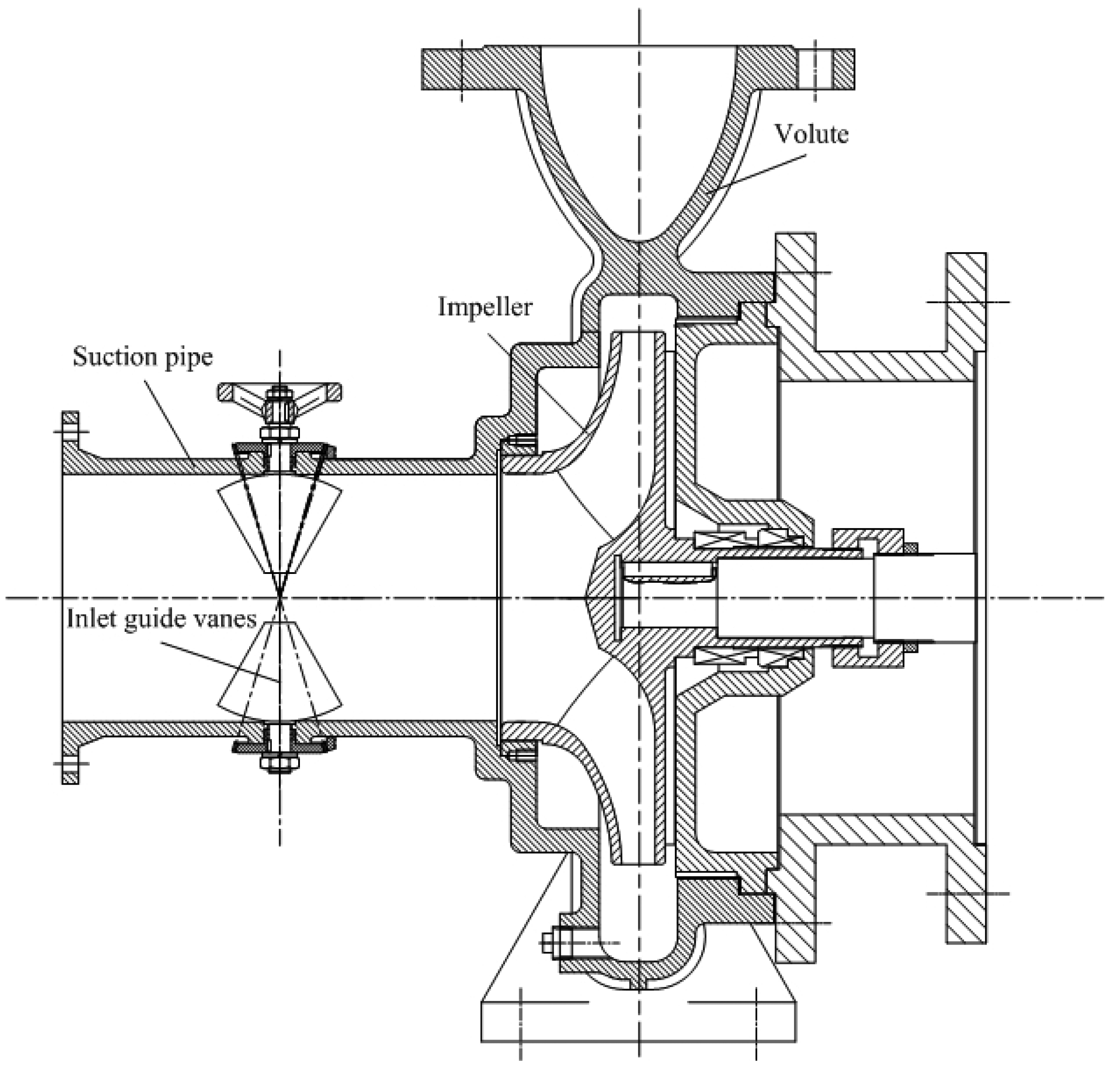
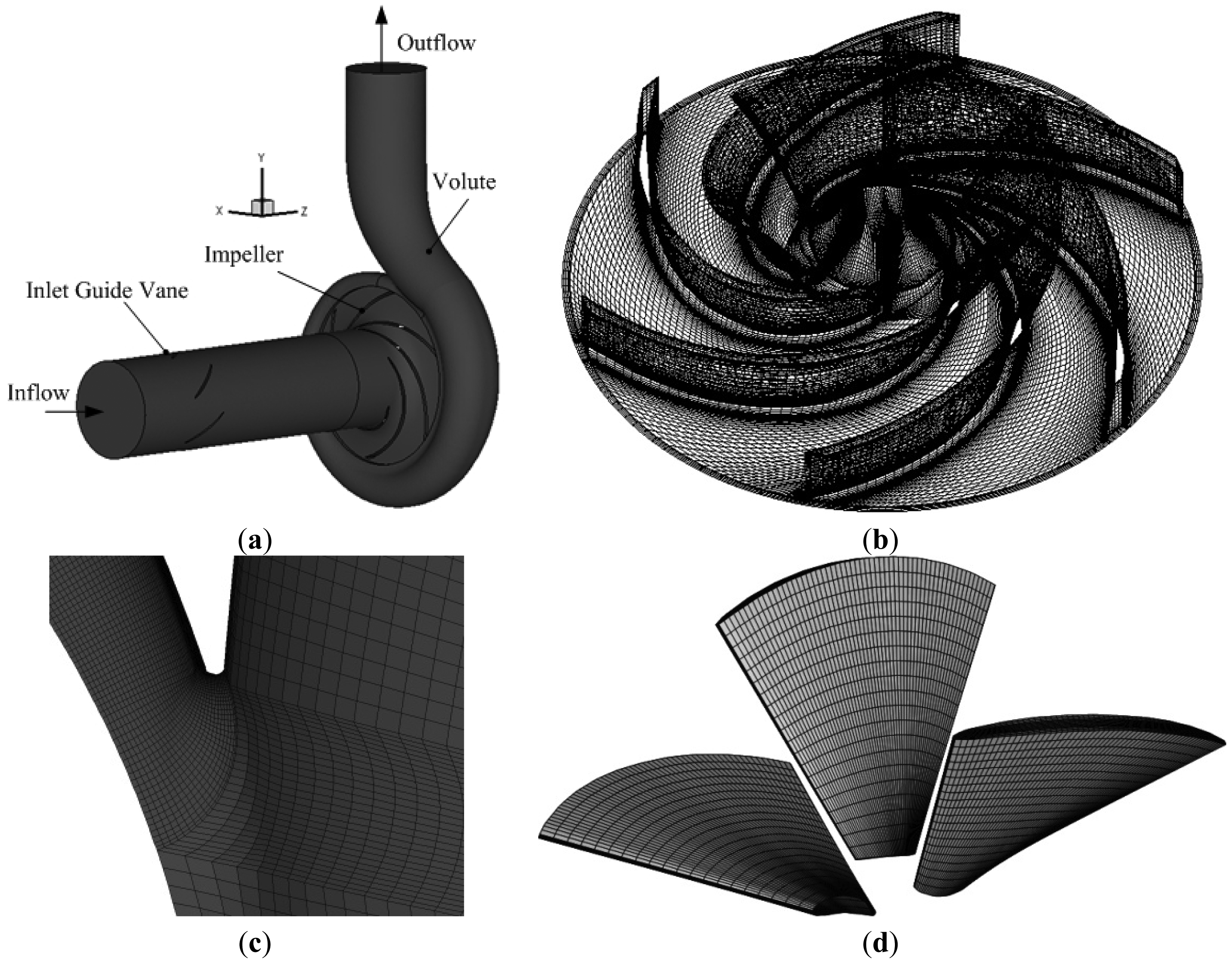
Figure 1 shows the sketch of the tested centrifugal pump with IGVs. The parameters of centrifugal pump and IGVs are listed in Table 1. As shown in Figure 1, the IGVs are equipped in the suction pipe in front of the impeller inlet. The distance between the central line of IGVs and the impeller inlet is 380 mm.
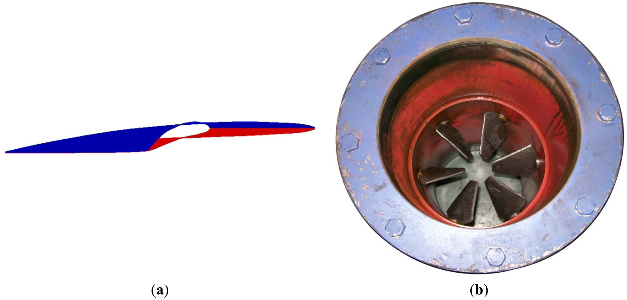
The IGVs have been specifically designed for the centrifugal pump impeller (whose original design did not include them) under the design constraint of enacting the non-impact condition at the impeller inlet at its nominal operating conditions (see reference [17]). The pressure and suction surfaces of designed vane are cambered as shown in Figure 2a. Six IGVs are evenly arranged in the suction pipe along the circumferential direction, as shown in Figure 2b. The prewhirl angle of IGVs can be regulated by the gears controlled by a hand wheel. When the tangential direction of the IGVs is aligned with the axial line of suction pipe, the prewhirl angle is defined as 0°. The prewhirl angle is denoted as positive as the circumferential velocity at the IGVs outlet has the identical direction with the impeller rotation.
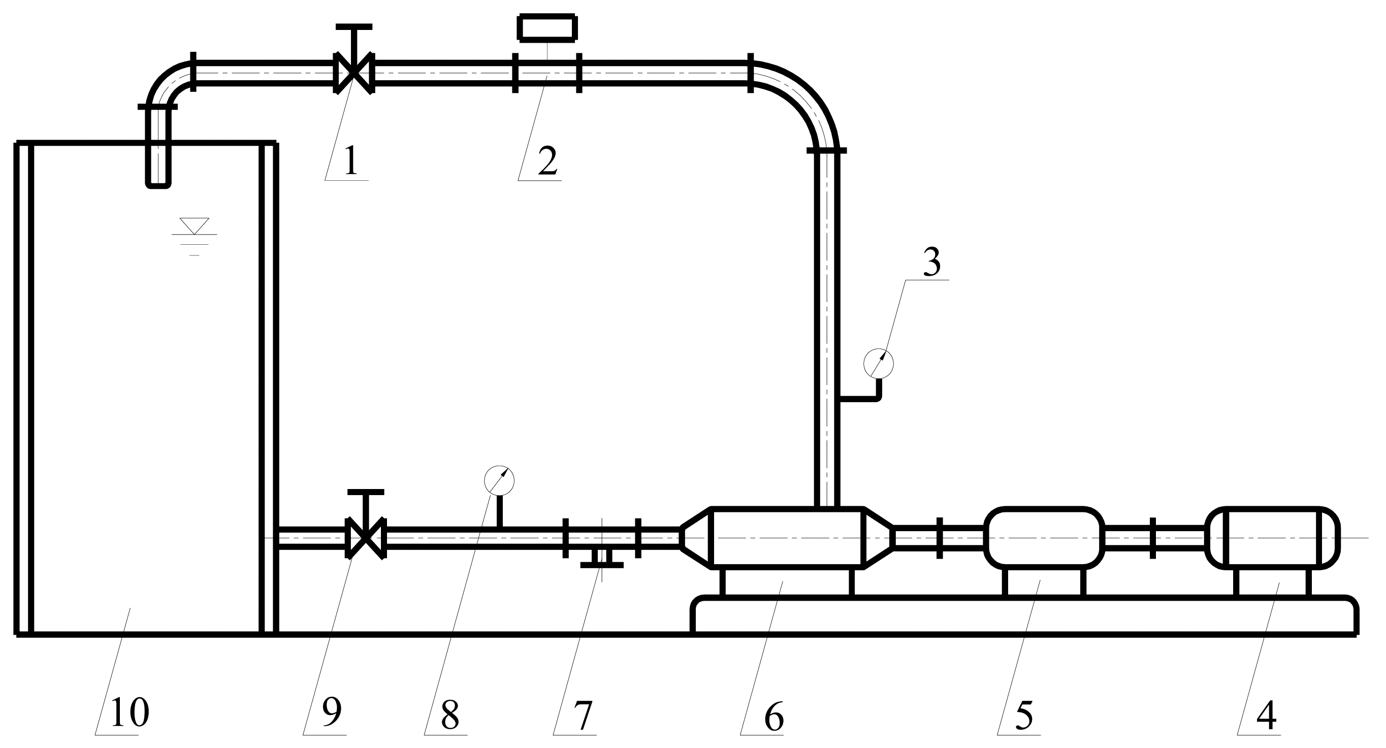
Figure 3 shows the rig for the experimental measurements. The test apparatus consists of three sections: (1) water supply section: the water tank, vacuum gauge and regulating valve; (2) pump section: the IGV, centrifugal pump, composite torque detector and motor; (3) outlet section: pressure gauge, turbine flowmeter and regulating valve. System uncertainty analysis testifies the error of the performance measurement for the centrifugal pump to be within ±0.36%. Pump performances, including head, efficiency and cavitation performance, were measured without and with IGVs for comparisons.
3. Numerical Calculations
3.1. Numerical Model and Calculation Method
The numerical model and method for simulating the flow filed of single phase (non-cavitation flow) in the centrifugal pump can be found in previous work by Tan et al. [17]. The fluid in the cavitation flow field is considered as a homogeneous and compressible mixed medium of liquid and vapor. The continuity and momentum equations in the Cartesian coordinates are given as follows:
The re-normalisation group (RNG) k-ε turbulence model is widely applied in turbomachines, which is suitable to simulate the complex flow in rotating and high curvature computational domain. As to the cavitation flow, the fluid in a centrifugal pump is compressible and made of liquid water and vapor. Therefore, the RNG k-ε turbulence model should be modified to improve the prediction accuracy for the cavitation condition. Considering the influence of compressibility on the cavitation flow, the turbulent viscosity is modified by introducing the function f(ρm) [19,20]. The turbulent viscosity μt is amended by:
The density function f(ρm) is defined as:
The liquid-vapor mass transfers due to cavitation are solved by the transport equation—based cavitation model proposed by Zwart et al. [21]:
In this model, a transport equation with source terms based on the homogeneous flow theory is used to solve the mass transfer between liquid and vapor phases. The fundamental assumption of this model is that the cavitation bubble does not interact with each other and the nucleation site density remains the same. However, with the development of cavitation the liquid volume fraction inevitably decreases, the nucleation site density should be modified accordingly. To further improve the modeling of the vaporization and condensation processes, the mass transfers for vaporization rate ṁvap and condensation rate ṁcon are modeled as follows:
The vapor pressure pv in most cavitation model is chosen as a constant according to the test temperature. However, it is actually influenced by the local turbulent pressure fluctuation, so this effect is taken into consideration in the present cavitation model by giving the modified vapor pressure pv as follows:
In the present calculation work, the commercial CFD code CFX 13.0 is employed. The equations solved in the calculation are the Navier-Stokes equations coupled with the RNG k-ε turbulence model and transport equation cavitation model. The spatial domain is discretized by using an element-based finite volume method.
In order to make the pump inlet pressure consistent with the experimental operation, the total pressure at the pump inlet is specified and the velocity direction is taken to be normal to the boundary. The mass flow at the pump outlet is selected. The scalable wall functions are imposed to solve the near-wall flow close to the no-slip wall over the impeller blades and sidewalls, the volute casing and the inlet and outlet pipe walls. The pressure at pump inlet decreases step by step until a convergence at each given operating condition in the cavitation flow calculations.
3.2. Computational Domain and Mesh
Figure 4 shows the computation domain and mesh of the centrifugal pump with IGVs. The computation domain is composed of three modules: suction pipe without or with IGVs, impeller and volute corresponding to the real pump in experiment. All the meshes are structural hexahedra in the computational domain, and the grids at the blade surface and volute tongue are locally refined in order to capture the flow details and improve the calculation accuracy, as shown in Figure 4b–d.
Five different mesh densities are used to calculate the pump performances at design point without cavitation, as shown in Table 2. The simulated results indicate the weak influence of mesh density on the pump head H and efficiency η in the present simulations. Therefore, the coarsest mesh with 1,804,742 elements is employed for the following calculations in order to reduce the calculation loads.
Here, H1 and η1 are the pump head and efficiency calculated by using the Mesh 1, respectively.
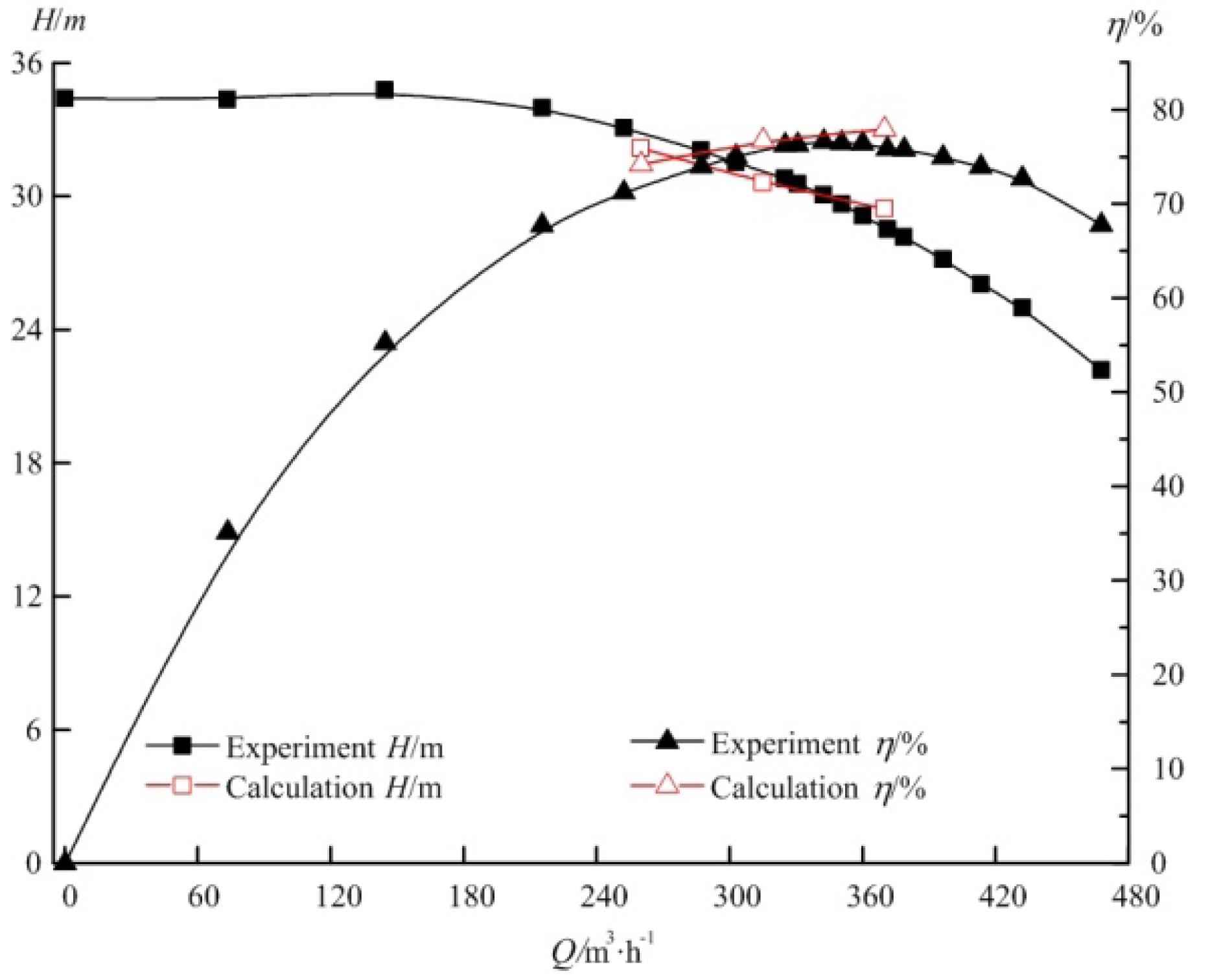
Figure 5 shows the comparison of pump head and efficiency without IGVs between the experimental and numerical results. There is a good quantitative agreement at the flow rate of 260–370 m3/h, with the maximum relative errors smaller than 5.0%, which demonstrates that numerical calculations simulate the pump performance accurately.
4. Results and Discussion
4.1. Performance without Cavitation
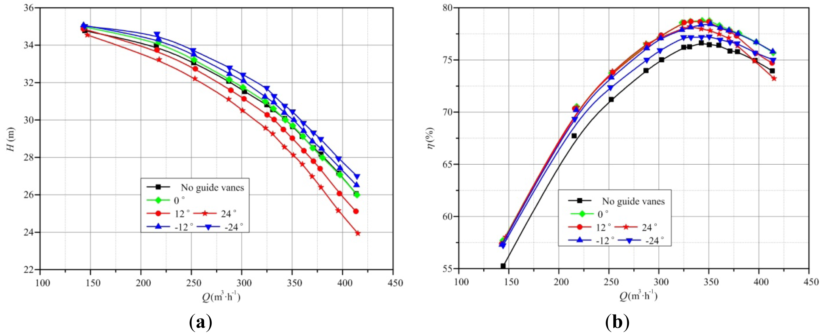
Figure 6 shows the experimental results of pump head and efficiency without and with IGVs for different flow rates. It can be seen from Figure 6a that the pump head is significantly affected by the prewhirl regulation of IGVs. The head increases as the negative prewhirl angle decreases, and decreases as the positive prewhirl angle increases. This can be easily explained by the Euler equation in hydraulic machineries as follows:
For the flow rate of 150–375 m3/h, the efficiencies of centrifugal pump under prewhirl regulation are all higher than that without IGVs, as shown in Figure 6b. The maximum efficiency increase is more than 2.0% around the designed condition region. Compared to the pump without IGVs, the improvement of pump efficiency for both positive and negative prewhirl regulations is mainly attributed to the optimized flow pattern at the impeller inlet and the improved flow field in the impeller [17,18]. Another reason is that the uniformly arranged vanes in the suction pipe homogenize the local flow field which is actually non uniform due to the blend and flange upstream of the suction pipe.
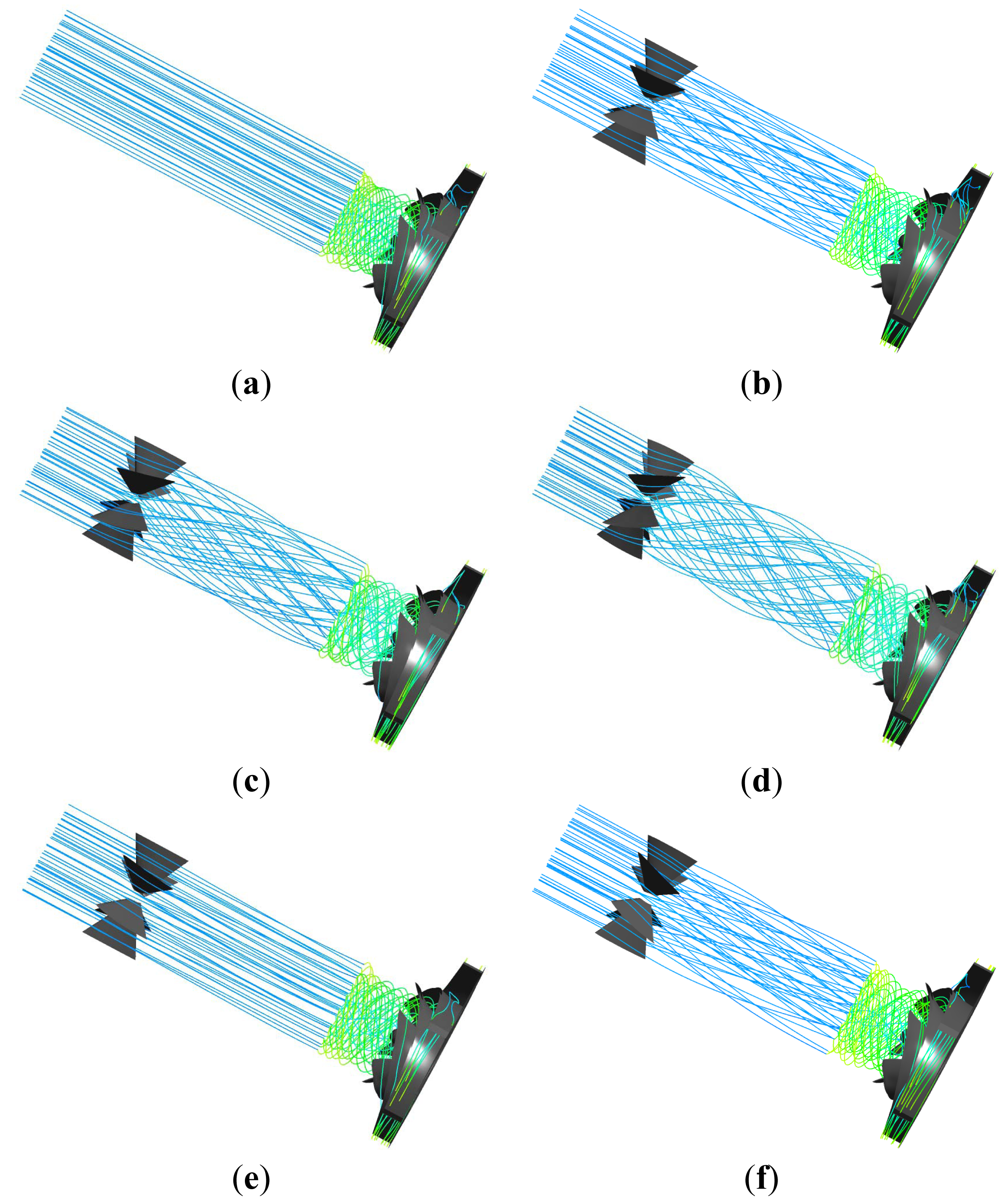
Figure 7 shows numerical results of three-dimensional streamlines in the pump suction pipe and impeller without and with IGVs at Q = 260 m3/h. The three-dimensional streamlines in the pump suction pipe and impeller start from the suction pipe inlet by sampling forty equally spaced points on this surface.
Without IGVs, the streamlines are straight in the suction pipe and then gradually rotate in the impeller with the same direction as the rotational impeller. Due to the asymmetrical three-dimensional geometry of IGVs, the fluid regulated by the IGVs has positive prewhirl at an IGV angle of 0°. For the positive prewhirl regulation, the fluid has an obvious positive circulation in the suction pipe while passing the IGVs. The rotation strength increases as the prewhirl angle increases from 12° to 24°, as shown in Figure 7c,d. For the negative prewhirl regulation, the circumferential movement of streamlines at −12° in the suction pipe is not as obvious as that at 12°, because the movement of fluid in suction pipe is also affected by the flow pattern in impeller, where the rotation intensity of fluid is far stronger than that in suction pipe with the opposite direction.
4.2. Performance with Cavitation
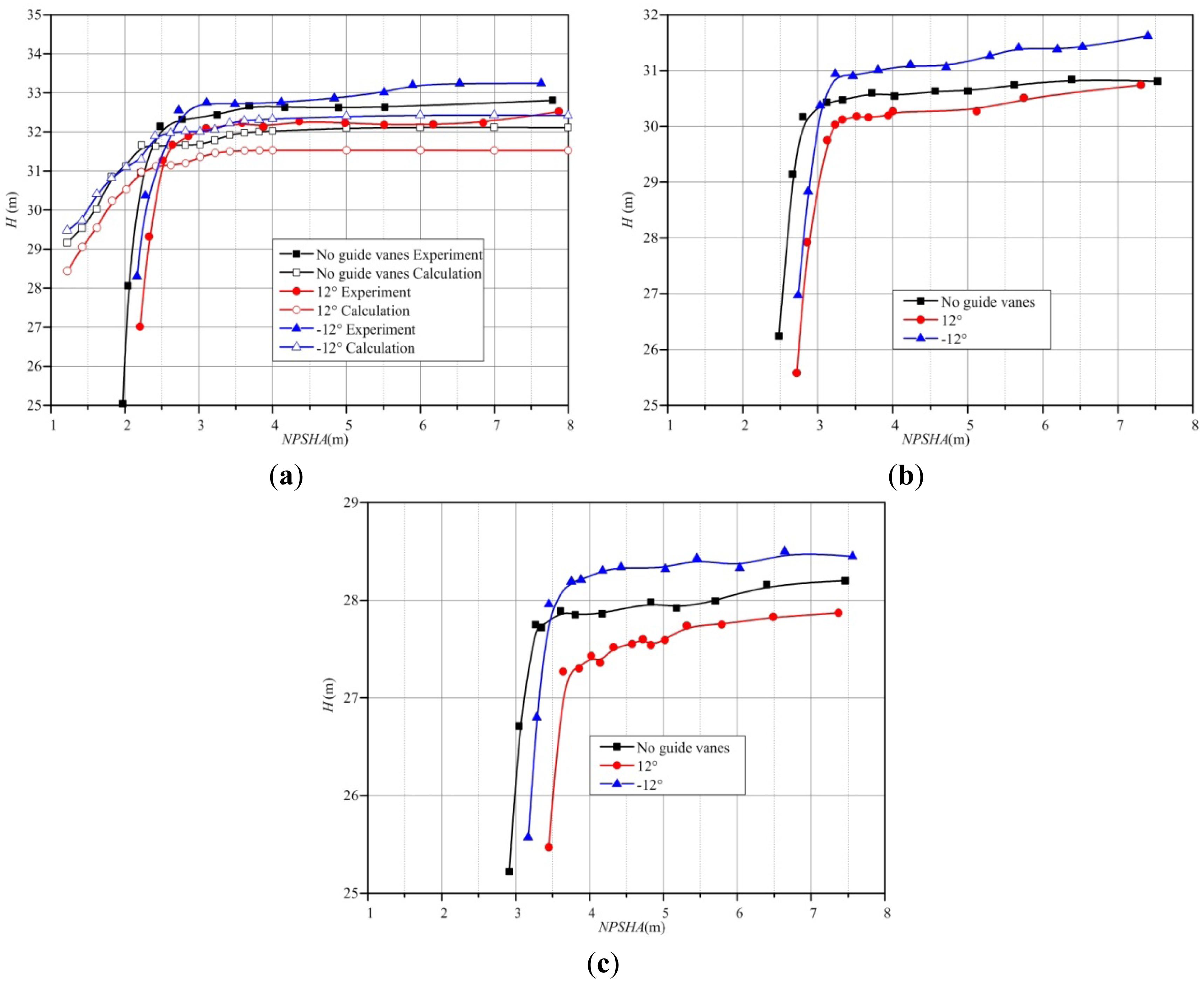
Figure 8 shows the measured head drop curves without and with IGVs at flow rates of Q = 260, 315 and 370 m3/h, respectively. Net positive suction head available (NPSHA), which is the difference between the total energy and vaporization energy for unit weight of the fluid at the pump inlet, is defined in Equation (10). The cavitation more likely occurs as NPSHA deceases:
In Figure 8a, the numerical results at Q = 260 m3/h are also given. The comparison between the measured and calculated results shows that the numerical simulation can accurately simulate the drop trend of pump head with the decrease of NPSHA, especially the sudden drop of H at the critical point. The value of NPSHA at which the head drops by 3% is usually defined as the net positive suction head critical (NPSHC). The IGVs installed in front of the pump induce hydraulic loss such as friction loss, impact loss and vortex shedding, so the total pressure at the inlet of pump with IGVs is lower than that without IGVs. Figure 8 illustrates that the values of NPSHC for centrifugal pumps with IGVs are larger than that without IGVs, which means that the pump with IGVs has worse cavitation performance. However, on the other hand, the influence of IGVs on the pump cavitation performance is very limited. The differences of NPSHC for the centrifugal pump without and with IGVs are less than 0.5 m at three flow rates. For this type of centrifugal pump, it still works well in most of the engineering application when the NPSHC varies 0.5 m.
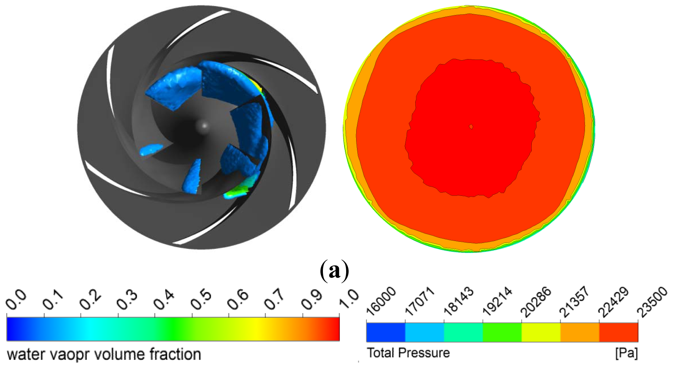
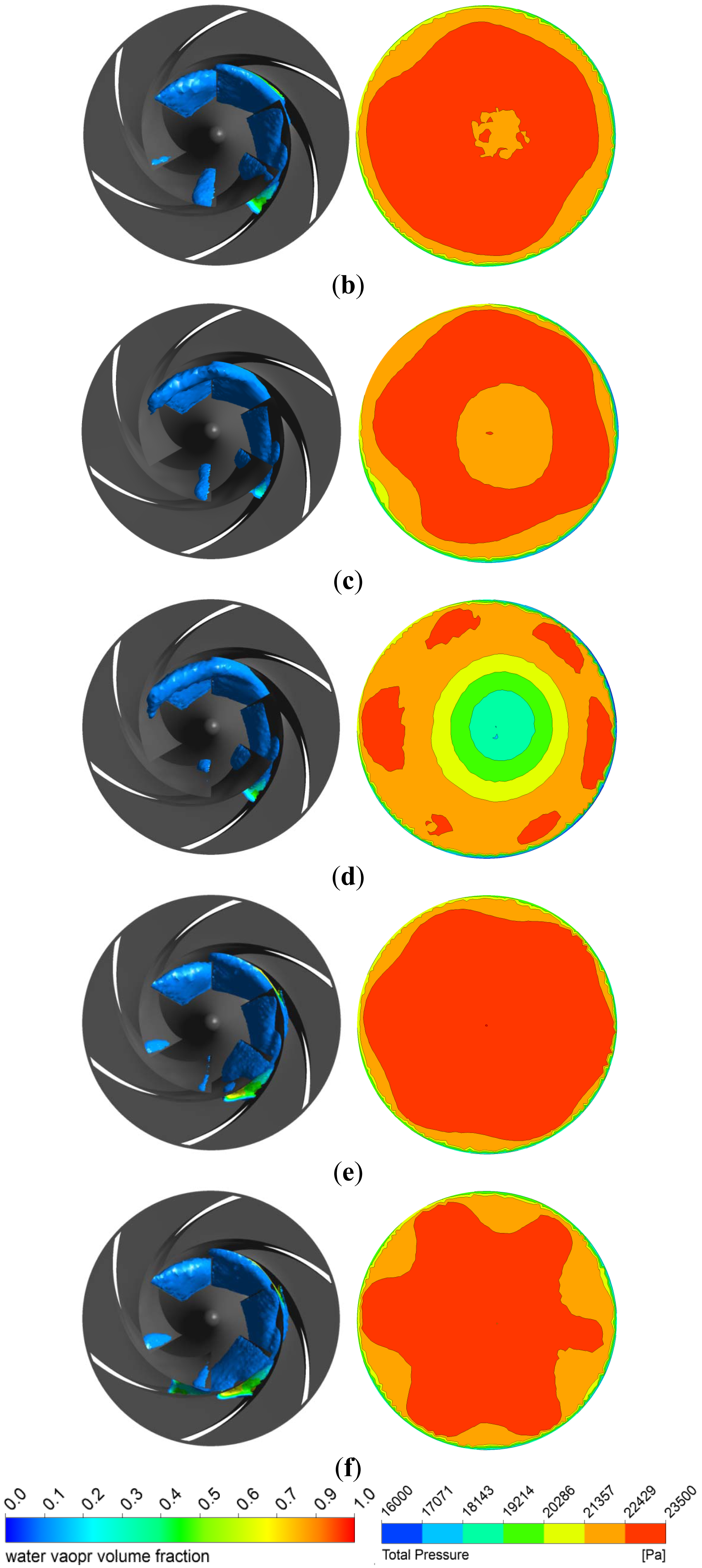
Figure 9 shows the volume fraction of vapor in the impeller and the total pressure contour at the impeller inlet by numerical simulation at the cavitation critical point of NPSHA = 2.0 m for Q = 260 m3/h. Due to the interaction of the rotational impeller and stable volute, the pressure distribution in the impeller is not symmetrical, which leads to the inhomogeneous cavity in the impeller. The total pressure contour at the impeller inlet becomes uneven when the pump has IGVs installed as shown in Figure 9b–f. For the positive prewhirl angle of 12° and 24° as shown in Figure 9c,d, the high pressure region shrinks as the prewhirl angle increases. Figure 9d shows that the central region is occupied by the low pressure fluid while the high pressure fluids are separated into six discontinuous regions when the angle increases to 24°. The change of the pressure distribution at the impeller inlet for negative angle is not as significant as the positive angle, but the total pressure contours are still influenced by the six IGVs as shown in Figure 9e,f.
Table 3 lists the total pressure at suction pipe inlet and impeller inlet. The area-weighted average method is used in the CFX 13.0 in present work to obtain the total pressure at suction pipe inlet and impeller inlet. The area-weighted average of the total pressure is the average value of the total pressure on a surface when the mesh element sizes are taken into account. In the numerical simulation, the total pressure at suction pipe inlet is set to a fixed value for five cases without and with IGVs according to the experimental condition; therefore, the six values of total pressure at suction pipe inlet are nearly the same in Table 3. However, the values at the impeller inlet are different due to the various losses induced by the IGVs at different prewhirl angles. The total pressure loss between the suction pipe inlet and impeller inlet for the case without IGVs is 255 Pa, approximately 1.0% of the total pressure at suction pipe inlet. When the IGVs' prewhirl angle is 24°, the corresponding values increase to 1777 Pa and 7.6%, which are consistent with the pressure contour in Figure 9d.
Undoubtedly, the total pressure losses in suction pipe with IGVs are larger than that without IGVs. For the tested centrifugal pump in this paper, the total pressure losses under positive prewhirl regulation are larger than that under negative prewhirl regulation with IGVs. The prewhirl strength of fluid obviously increases as the angle increases when the IGVs are regulated to positive angle. This is also apparent from the elongated streamlines as shown in Figures 7c,d. The extended streamlines mean larger friction loss and probably deteriorate the flow pattern. Taking the opposite prewhirl angles 12° and −12° for example, the total pressure loss of positive regulation is about twice of that of negative regulation.
Figure 10 shows the total pressure contour at four cross sections between IGVs and impeller inlet with equal distance of 0.1 m for the IGVs' angle of 24°. Under regulation of IGVs, six divided regions of local high pressure appear near the suction pipe wall, as shown in Figure 10b–e. As the fluid flows downstream, the six high pressure regions become circumferential uneven, and the areas of those regions gradually reduce, which indicates that the velocity circulation weakens accordingly. Therefore, the distance between the IGVs and impeller has obvious influence on the effects of prewhirl regulation of IGVs.
5. Conclusions
The effects of prewhirl regulation by IGVs on head, efficiency and cavitation performances of a centrifugal pump are investigated by experimental measurements and numerical simulation. The experimental results show that the efficiency of pump with IGVs is higher than that without IGVs, the highest efficiency improvement is more than 2.0% around the designed conditions. The head of centrifugal pump under positive or negative prewhirl regulation is decreased or increased, respectively, due to the variation of circumferential velocity at the impeller inlet. The centrifugal pump cavitation performance is degraded when it installs the IGVs, but the variation of NPSHC is less than 0.5 m.
The numerical method is validated by comparing the experimental and calculated results for both non-cavitation and cavitation flows in the centrifugal pump. The positive or negative rotational streamlines in the suction pipe and impeller clearly show how the IGVs regulate the flow pattern in the centrifugal pump. The calculated results reveal the cavity distribution in the impeller and the total pressure contour at the impeller inlet. Moreover, the quantitative analyses on the total pressure loss between the suction pipe inlet and impeller inlet are realized for the centrifugal pump without and with IGVs. Numerical results show that the influence of IGVs on the cavitation performance of centrifugal pump is limited with the maximum total pressure drop of 1777 Pa (about 7.6% of the total pressure at the suction pipe inlet) for the prewhirl angle of 24°.
For the centrifugal pump tested in this paper, in the range of prewhirl angle −24° to 24°, the prewhirl regulation of IGVs can greatly increase or decrease the centrifugal pump head and improve the efficiency in a wide operation range, and induce limited negative influence on the cavitation performance.
Acknowledgments
This work was supported by the National Natural Science Foundation of China (Grant number 51176088 and 51179090) and the Open Research Fund Program of State Key Laboratory of Hydroscience and Engineering (Grant number sklhse-2012-E-02).
Conflicts of Interest
The authors declare no conflict of interest.
References
- Fukutomi, J.; Nakamura, R. Performance and internal flow of cross-flow fan with inlet guide vane. JSME Int. J. Ser. B Fluids Therm. Eng. 2005, 48, 763–769. [Google Scholar]
- Coppinger, M.; Swain, E. Performance prediction of an industrial centrifugal compressor inlet guide vane system. Proc. Inst. Mech. Eng. Part A J. Power Energy 2000, 214, 153–164. [Google Scholar]
- Liou, T.M.; Lee, H.L.; Liao, C.C. Effects of inlet guide-vane number on flow fields in a side-dump combustor. Exp. Therm. Fluid Sci. 2001, 24, 11–23. [Google Scholar]
- Mohseni, A.; Goldhahn, E.; van den Braembussche, R.A.; Seume, J.R.; Goldhahn, E. Novel IGV designs for centrifugal compressors and their interaction with the impeller. J. Turbomach. 2012, 134. [Google Scholar] [CrossRef]
- Ferro, L.; Gato, L.; Falcoa, A. Design and experimental validation of the inlet guide vane system of a mini hydraulic bulb-turbine. Renew. Energy 2010, 35, 1920–1928. [Google Scholar]
- Johnston, R.; Fleeter, S. Inlet guide vane wakes including rotor effects. J. Fluids Struct. 2001, 15, 235–253. [Google Scholar]
- Cui, M.M. Unsteady flow around suction elbow and inlet guide vanes in a centrifugal compressor. Proc. Inst. Mech. Eng. Part G J. Aerosp. Eng. 2006, 220, 11–28. [Google Scholar]
- Soranna, F.; Chow, Y.C.; Uzol, O.; Katz, J. The effect of inlet guide vanes wake impingement on the flow structure and turbulence around a rotor blade. J. Turbomach. 2006, 128, 82–95. [Google Scholar]
- Oro, J.M.F.; Diaz, K.M.A.; Morros, C.S.; Marigorta, E.B. Unsteady flow and wake transport in a low-speed axial fan with inlet guide vanes. J. Fluids Eng. 2007, 129, 1015–1029. [Google Scholar]
- Oro, J.M.F.; Diaz, K.M.A.; Morros, C.S.; Marigorta, E.B. Analysis of the deterministic unsteady flow in a low-speed axial fan with inlet guide vanes. J. Fluids Eng. 2008, 130. [Google Scholar] [CrossRef]
- Tan, J.; Wang, X.; Qi, D.; Wang, R. The effects of radial inlet with splitters on the performance of variable inlet guide vanes in a centrifugal compressor stage. Proc. Inst. Mech. Eng. Part C J. Mech. Eng. Sci. 2011, 225, 2089–2105. [Google Scholar]
- Zhou, L.; Fan, H.-Z.; Wei, W.; Cai, Y.-H. Experimental and numerical analysis of the unsteady influence of an inlet guide vane. Proc. Inst. Mech. Eng. Part C J. Mech. Eng. Sci. 2011, 226, 660–680. [Google Scholar]
- McAlpin, R.L.; Holm, R.E.; Talley, P.L.; Bernstein, H.L. Failure analysis of inlet guide vanes. J. Eng. Gas Turbines Power 2003, 125, 236–240. [Google Scholar]
- Coutier-Delgosha, O.; Hofmann, M.; Stoffel, B.; Fortes-Patella, R.; Reboud, J.L. Experimental and numerical studies in a centrifugal pump with two-dimensional curved blades in cavitating condition. J. Fluids Eng. 2003, 125, 970–978. [Google Scholar]
- Bachert, R.; Stoffel, B.; Dular, M. Unsteady cavitation at the tongue of the volute of a centrifugal pump. J. Fluids Eng. 2010, 132. [Google Scholar] [CrossRef]
- Ding, H.; Visser, F.C.; Jiang, Y.; Furmanczyk, M. Demonstration and validation of a 3D CFD simulation tool predicting pump performance and cavitation for industrial applications. J. Fluids Eng. 2011, 133. [Google Scholar] [CrossRef]
- Tan, L.; Cao, S.L.; Gui, S.B. Hydraulic design and pre-whirl regulation law of inlet guide vane for centrifugal pump. Sci. China Technol. Sci. 2010, 53, 2142–2151. [Google Scholar]
- Tan, L.; Cao, S.L.; Wang, Y.M.; Zhu, B.S. Influence of axial distance on pre-whirl regulation by the inlet guide vanes for a centrifugal pump. Sci. China Technol. Sci. 2012, 55, 1037–1043. [Google Scholar]
- Coutier-Delgosha, O.; Reboud, J.L.; Fortes-Patella, R. Evaluation of the turbulence model influence on the numerical simulations of unsteady cavitation. J. Fluids Eng. 2003, 125, 38–45. [Google Scholar]
- Tan, L.; Cao, S.L.; Wang, Y.M.; Zhu, B.S. Numerical simulation of cavitation in a centrifugal pump at low flow rate. Chin. Phys. Lett. 2012, 29. [Google Scholar] [CrossRef]
- Zwart, P.J.; Gerber, A.G.; Belamri, T. A Two-Phase Flow Model for Predicting Cavitation Dynamics. Proceedings of the 5th International Conference on Multiphase Flow (ICMF), Yokohama, Japan, 30 May–3 June 2004.


| Component | Item | Value |
|---|---|---|
| Centrifugal pump | Volumetric flow rate Q (m3/h) | 340 |
| Head H (m) | 30 | |
| Rotational speed n (r/min) | 1,450 | |
| Blade numbers of impeller Zi | 6 | |
| Diameter of suction pipe D0 (mm) | 200 | |
| Diameter of impeller out D2 (mm) | 329 | |
| IGVs | Hub of IGVs (mm) | 40 |
| Shroud of IGVs (mm) | 200 | |
| Blade numbers of vanes Zg | 6 | |
| Blade angle at inlet βgi (°) | 90 | |
| Items | Mesh 1 | Mesh 2 | Mesh 3 | Mesh 4 | Mesh 5 |
|---|---|---|---|---|---|
| Suction pipe | 723,855 | 723,855 | 723,855 | 723,855 | 723,855 |
| Impeller | 417,396 | 1,048,831 | 1,942,195 | 2,714,058 | 3,696,570 |
| Volute | 663,491 | 663,491 | 663,491 | 663,491 | 663,491 |
| Whole passage | 1,804,742 | 2,436,177 | 3,329,541 | 4,101,404 | 5,083,916 |
| H/H1 | 1 | 0.99428 | 0.99455 | 0.99394 | 0.99355 |
| η/η1 | 1 | 1.00331 | 1.00336 | 1.00361 | 1.00380 |
| Pump | Total pressure at pipe inlet (Pa) | Total pressure at impeller inlet (Pa) | Total pressure difference (Pa) |
|---|---|---|---|
| No IGVs | 23,341 | 23,086 | 255 |
| IGVs 0° | 23,305 | 22,802 | 503 |
| IGVs 12° | 23,306 | 22,499 | 807 |
| IGVs 24° | 23,305 | 21,528 | 1777 |
| IGVs −12° | 23,306 | 22,828 | 478 |
| IGVs −24° | 23,304 | 22,462 | 842 |
© 2014 by the authors; licensee MDPI, Basel, Switzerland. This article is an open access article distributed under the terms and conditions of the Creative Commons Attribution license ( http://creativecommons.org/licenses/by/3.0/).
Share and Cite
Tan, L.; Zhu, B.; Cao, S.; Wang, Y.; Wang, B. Influence of Prewhirl Regulation by Inlet Guide Vanes on Cavitation Performance of a Centrifugal Pump. Energies 2014, 7, 1050-1065. https://doi.org/10.3390/en7021050
Tan L, Zhu B, Cao S, Wang Y, Wang B. Influence of Prewhirl Regulation by Inlet Guide Vanes on Cavitation Performance of a Centrifugal Pump. Energies. 2014; 7(2):1050-1065. https://doi.org/10.3390/en7021050
Chicago/Turabian StyleTan, Lei, Baoshan Zhu, Shuliang Cao, Yuchuan Wang, and Binbin Wang. 2014. "Influence of Prewhirl Regulation by Inlet Guide Vanes on Cavitation Performance of a Centrifugal Pump" Energies 7, no. 2: 1050-1065. https://doi.org/10.3390/en7021050
APA StyleTan, L., Zhu, B., Cao, S., Wang, Y., & Wang, B. (2014). Influence of Prewhirl Regulation by Inlet Guide Vanes on Cavitation Performance of a Centrifugal Pump. Energies, 7(2), 1050-1065. https://doi.org/10.3390/en7021050