Article

Finite Element Method Modeling of Sensible Heat Thermal Energy Storage with Innovative Concretes and Comparative Analysis with Literature Benchmarks

by
Claudio Ferone
1,*,
Francesco Colangelo
1,†,
Domenico Frattini
1,†,
Giuseppina Roviello
1,†,
Raffaele Cioffi
1,† and
Rosa Di Maggio
2,†
1
Department of Engineering, University of Naples "Parthenope", National Interuniversity Consortium of Materials Science and Technology (INSTM), Research Group Naples Parthenope, Centro Direzionale Naples, Isola C4, 80143 Naples, Italy
2
Department of Civil, Environmental and Mechanical Engineering, University of Trento, Via Belenzani 12, 38122 Trento, Italy
*
Author to whom correspondence should be addressed.
These authors contributed equally to this work.
Energies 2014, 7(8), 5291-5316; https://doi.org/10.3390/en7085291
Submission received: 17 June 2014 / Revised: 22 July 2014 / Accepted: 11 August 2014 / Published: 15 August 2014
(This article belongs to the Special Issue Energy Efficient Building Design and Operation 2014)

Abstract

:
Efficient systems for high performance buildings are required to improve the integration of renewable energy sources and to reduce primary energy consumption from fossil fuels. This paper is focused on sensible heat thermal energy storage (SHTES) systems using solid media and numerical simulation of their transient behavior using the finite element method (FEM). Unlike other papers in the literature, the numerical model and simulation approach has simultaneously taken into consideration various aspects: thermal properties at high temperature, the actual geometry of the repeated storage element and the actual storage cycle adopted. High-performance thermal storage materials from the literatures have been tested and used here as reference benchmarks. Other materials tested are lightweight concretes with recycled aggregates and a geopolymer concrete. Their thermal properties have been measured and used as inputs in the numerical model to preliminarily evaluate their application in thermal storage. The analysis carried out can also be used to optimize the storage system, in terms of thermal properties required to the storage material. The results showed a significant influence of the thermal properties on the performances of the storage elements. Simulation results have provided information for further scale-up from a single differential storage element to the entire module as a function of material thermal properties.

Graphical Abstract

1. Introduction

Design of Sensible Heat Thermal Energy Storage Systems and High Performance Materials

Increasing interest has been directed towards concentrated solar power (CSP) plants, integrated with thermal energy storage (TES) systems, by means of very different solar plant layouts, storage principles, materials used and operating strategies, as reported by Gil et al. [1] and Medrano et al. [2].
Solar collectors can be also used for high performance buildings to provide utilities and services in a more efficient way in terms of primary energy used and costs [3,4,5]. Among TES options, one of the most suitable and economically feasible is represented by sensible heat TES (SHTES) in solid media [6,7,8], using traditional and innovative materials, such as high temperature concretes [9], fly ash/silica fume based concretes [10,11] and graphite concretes (A4) [12,13].
Design of a SHTES module, and determination of its operating conditions, is not easy due to the fluid dynamics and heat transfer phenomena involved in the storage process between heat transfer fluid (HTF), piping and storage material [14,15]. Particularly, the thermal energy stored in a SHTES module can be essentially expressed as:
Qnom = ρsol·Vsol·csol·∆Tnom
For the correct design of the overall storage system, prediction of its dynamic behavior during storage cycles is needed for performance evaluation in building applications, but in the design Equation (1) no information about time evolution of the system is provided. In order to take into account the influence of dynamic storage cycle, i.e., time dependence, the above equation can be modified as follows:
Q(t)eff = ρsol·Vsol·csol·∆T(t)eff
The maximum average temperature and the temperature profile within the solid medium, during repeated thermal storage cycles, are the most important parameters to evaluate the effective energy stored, Qeff, in the module. For this purpose, confident numerical simulations can be used to study the thermal performance of SHTES modules with different storage materials. Several studies are available on numerical modeling of TES systems, using the finite element method (FEM) to investigate separately the various thermophysical phenomena involved [14,15,16,17,18,19]. Nonetheless, in order to effectively refine the design process, the numerical modeling and the simulation approach should simultaneously take into consideration the following aspects: storage material thermal properties at high temperatures, the real geometry of the repeated differential storage element, and the operating storage cycle to be actually used.
Material selection and design for building applications essentially relies on compressive/tensile strength [20,21], ductility and casting/curing feasibility [22]. Actually the most relevant aspects for thermal storage application are thermal conductivity, heat capacity, thermal stability, along with compatibility with different materials, reversibility for large number of cycles, low heat losses, environmental impact and costs [23,24]. Concrete-based materials, derived from building and construction applications, offer the possibility to easily diversify physical, thermal and mechanical properties, by means of an application oriented mix design, because significant improvements of TES module performance depend on high temperature properties of the material used. A very attractive challenge, reported in a number of studies to increase greenness, durability and sustainability of such materials [25,26,27] is represented by the selection of natural or artificial aggregates [28,29], valorization of wastes [30,31], recycling of coal fly ash [32,33,34] or blast furnace slag [35].
Fiber-reinforced concretes (FCs) [36,37], geopolymer-based materials [38,39] and other cementitious composites have been assessed to be more eco-compatible than traditional concrete and can be potentially employed for storage applications due to their reliable mechanical and thermal properties. Especially, as regard geopolymeric materials, a number of literatures have assessed their fire resistance [40,41], high resistance to high temperature [42,43] and also the noticeable thermal-shock resistance in repeated exposure to high temperatures [44] as a consequence of the low free water content. These features are highly desirable when considering a cementitious material as eligible solid medium for thermal storage applications. An overview of a comprehensive design approach for SHTES system design, based on concrete-derived materials, is reported in Figure 1.
Figure 1. Schematization of sensible heat thermal energy storage (SHTES) design.
Energies 07 05291 g001
Finally, the economic investment for a SHTES system is of fundamental importance to optimize the operations and increase the profitability of this technology in high performance buildings. Even if the major part of capital costs are due to the tube register heat exchanger, considerable total cost savings can be achieved by using alternative low cost materials. As reported by Fernandez et al. [23], the storage material cost depends essentially on its properties, like density, specific heat capacity, etc., and finally on the total weight of the material employed in the SHTES module fabrication. In order to reduce costs, lightweight but high thermal performance materials are required for large SHTES system realization.
This paper is focused on SHTES in solid media and numerical simulation of their transient behavior during the charging/discharging phases using the FEM. Specific attention has been dedicated to the influence of thermal properties, as collected in the literature or experimentally measured for several materials tested during the research activities presented in this work. Selected high-performance thermal storage materials from the literature have been tested and used as reference benchmarks. Concretes with recycled-plastic aggregates and a geopolymer concrete have been prepared and tested for the comparative analysis. Their thermal properties have been measured and implemented in the numerical model to preliminarily evaluate their application in thermal storage.

2. Materials and Methods

2.1. Design Criteria and Simulation Approach for Sensible Heat Thermal Energy Storage Differential Elements

Considering a 6 × 6 tube register in square arrangement, a single storage module with total height H, width W and length L, can be considered as a symmetric disposition in a 3D space of a repeating differential element, characterized by the diameter di of the internal tube and the tube spacing da as geometrical parameters. Figure 2 shows the frontal view of a SHTES module, to better understand the physical meaning of these quantities.
Figure 2. SHTES module, frontal view.
Energies 07 05291 g002
The configuration described above is symmetric and modular, because it can be considered as the repetition of 36 differential storage elements, disposed in parallel. The thermal analysis of the SHTES module can be reduced to the study of heat transfer phenomena into a prismatic element with a cylindrical cavity in the center, representing the flow channel for the HTF flow, which is the storage element considered in this work. This differential element, differently from cylindrical elements considered in other works [17,45], depicts without geometric approximations the actual repeating differential storage element. In Figure 3, the 3D sketch of the differential storage element, assumed as the computational domain for unsteady heat transfer simulation, is shown with the grid employed for calculation.
The grid in Figure 3 has 1,150,000 triangular prism elements, 596,190 nodes and very good mesh quality parameters, (i.e., aspect ratio and skewness), the length L of differential element is fixed to 1 m, the inner diameter di of tube is 0.02 m for all the simulations and the distance da between two flow channels, i.e., the edge of the square cross-section, is 0.08 m.
Figure 3. 3D model for the differential storage element, with grid: (a) overall view; (b) isometric view; (c) frontal view; and (d) lateral view.
Energies 07 05291 g003
TES, based on sensible heat in a solid medium, is essentially governed by the following equations:
T sol t = α sol 2 T sol
Q = T 0 T f ρ sol ( T sol ) · V sol · c sol ( T sol ) · Δ T ( T sol ) d T sol
ksol(Tsol) = αsol(Tsol)·ρsol(Tsolcsol(Tsol)
The first equation is a form of the energy equation, the second one is used to calculate the effective thermal energy transferred to the solid during charging, and the last one is the constitutive equation for thermophysical properties involved. The boundary conditions (BC) and initial conditions (IC) to be numerically solved depend on the storage cycle imposed to SHTES element. In this work no thermal losses to environment and uniform temperature at the beginning of the charge phase are assumed, so that the resulting BC and IC can be written as follows:
BC: k · ( T n ) wall = 0 on element external walls
IC: T (x, y, z, t = 0) = T0 in the whole solid medium
According to Tamme et al. [17] and Salomoni et al. [45], the following conditions have been applied to the model:
(a)
the storage materials are considered homogeneous and isotropic;
(b)
for the length L, the variation of temperature in axial direction can be neglected;
(c)
the steel pipes, due to their very high thermal conductivity, have a negligible effect on heat transfer to the solid media;
(d)
the operating delta T for the element is 40 K (from 623 K to 663 K), so that thermal properties are assumed to be constant;
(e)
the HTF is considered as an infinite power tank during a complete thermal cycle;
(f)
for the operating storage cycle, the charging period lasts 3600 s, and the following break period lasts 3600 s.
As regards the actual operating storage cycle to be simulated, at the beginning of the charging phase, each storage material was considered at the constant and uniform temperature of 623 K. The thermal cycle starts with a sudden increase of HTF temperature to the maximum value of 663 K and, after 1 h of break, it rapidly decreases back to 623 K, which represents the IC of the discharging phase. For each material, considering Equation (1) and the module geometry proposed above, two different simulation approaches have been applied to the differential storage element: (i) by keeping the total volume (Vtot) constant; and (ii) by keeping the nominal stored energy (Qnom) constant. The temperature profiles at the wall, the contour maps into the solid media and other quantitative results for the differential element considered, such as solid mass (msol), effective thermal energy stored (Qeff), storage efficiency (ηstorage) and actual power density, have been reported and discussed to show the performances of storage materials studied.

2.2. Storage Materials Selected From Literature Review on Sensible Heat Thermal Energy Storage

Different materials developed and tested in the literature for TES application have been selected. Ozger et al. [46] prepared and tested a plain concrete (PC), composed of natural aggregates such as gravel, limestone sand from crushed dolomite, with a type II cement (CEM II/A-L 42.5N, [47]) as binder, and a FC, prepared with the same aggregates of PC, added with 0.5% v/v of recycled synthetic fiber. Characterization of thermal properties was carried out at 623 K.
The materials developed by Laing et al. [9] were a high-temperature concrete (HT) and a castable ceramic (CC). The former was based on blast furnace cement as binder, iron oxide aggregate from steel production, fly ash and other materials; the latter was prepared with a binder containing pure Al2O3, iron oxides and accelerator agent to reduce viscosity and improve workability. For both materials, mix proportions were not specified and also aggregates used were not well defined, but thermal properties reported were determined at 623 K.
A new heat storage A4, presented by Guo et al. [12], has very interesting mix design and thermal properties. A4 contained components characterized by high specific heat capacity, such as basalt and bauxite as aggregates, steel fiber, aluminum micropowder, calcium-aluminate cement as binder, and 5% of graphite to increase thermal conductivity. Even in this case, reported properties were determined at high temperature (623 K) for heat storage purpose. The selected materials and their properties retrieved from the indicated references are summarized in Table 1.
The specific heat capacity for A4 has been necessarily estimated because no information about this property was reported. A linear rule of mixture based on available A4 mix proportion has been used for the estimation. The stability of above reported properties has been assessed by characterization tests performed at different temperatures [9,12,46]. Further, the selection of these specific storage materials has been driven by the fact that their thermal properties at high temperatures are reported. The reliability and applicability of these materials for TES purpose is so confirmed, and these data can be used in simulations.
Table 1. Storage material selected in the literature for SHTES. PC: plain concrete; HT: high-temperature concrete; CC: castable ceramic; A4: graphite concrete; and FC: fiber-reinforced concrete.
MaterialDensity ρsol (kg/m3)Specific heat capacity csol (J/(kg·K))Thermal conductivity ksol (W/(m·K))Thermal diffusivity αsol × 107 (m2/s)Volumetric heat capacity Cvol (kW·h/(m3·K))Reference
PC24518101.025.140.551[46]
HT27509161.003.970.700[9]
CC35008661.354.450.842[9]
A42680950 *2.439.540.707[12]
FC24406301.167.550.427[46]
* Estimated value.
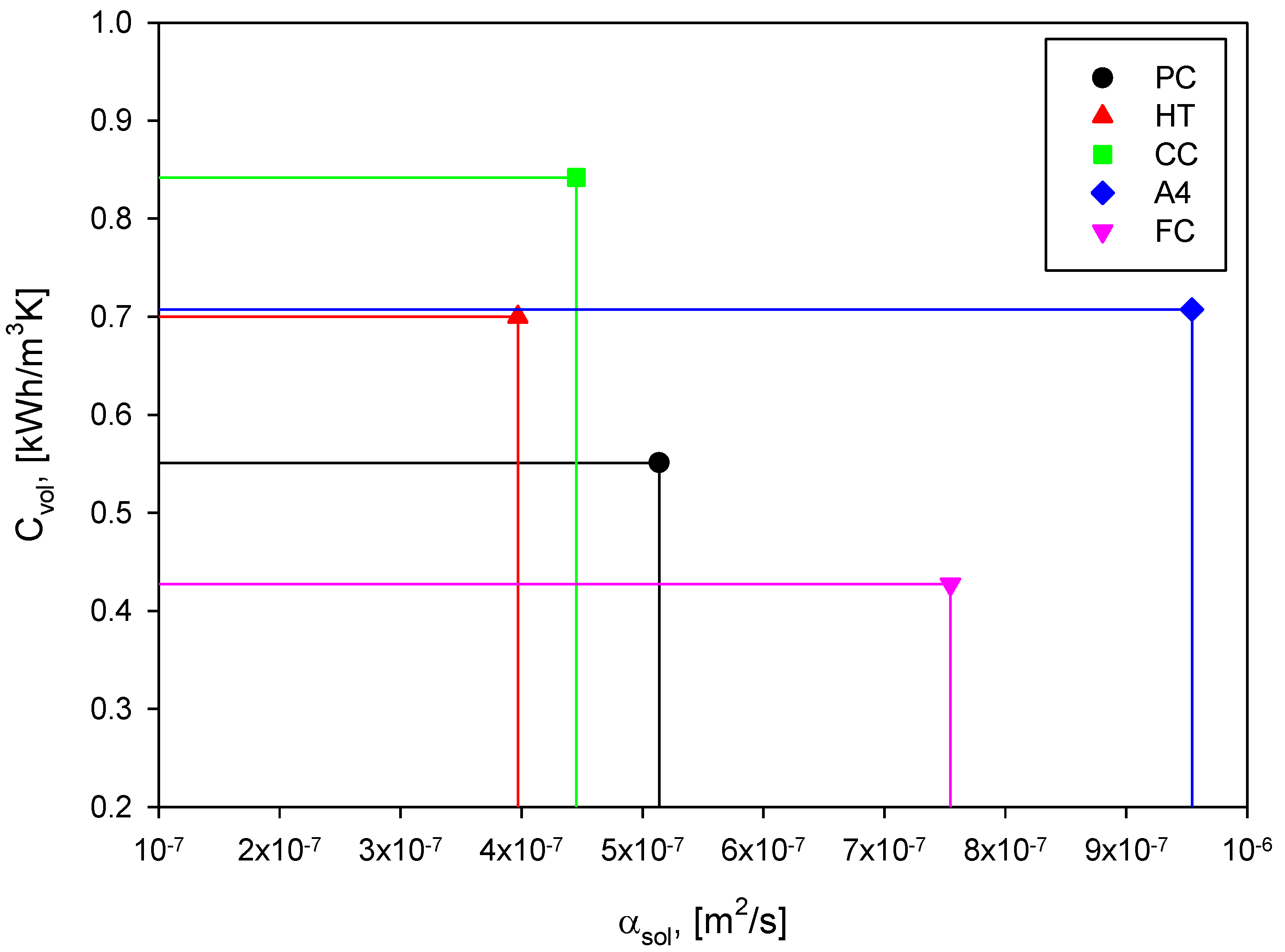
Figure 4 shows a simple map where storage materials have been arranged in terms of volumetric heat capacity Cvol, calculated as ρsol·csol, and thermal diffusivity αsol, calculated as ksol/(ρsol·csol). In this way, the rectangular area described by perpendicular lines and symbols, represents the value of thermal conductivity.
Figure 4. Thermal properties of selected storage materials.
Energies 07 05291 g004
The vertical axis represents the capacitive behavior of the material, while the horizontal axis provides qualitative information about the heat transport behavior. In fact a high capacity influences the storage volume, and hence the power density; a high thermal diffusivity increases the heat transfer rate of the system [9]. The data comparison proposed above is of interest because it allows making some considerations:
(1)
For a fixed value of the rectangular area, i.e., thermal conductivity, the constitutive equation for thermal properties describes a hyperbola, hence a high value of the thermal diffusivity corresponds to a low value of the volumetric heat capacity and vice versa;
(2)
Storage materials, with similar values of thermal conductivity, can behave very differently and the simple increase of the thermal conductivity value, as suggested in [17,45], could be insufficient to improve overall thermal performances;
(3)
A proper design of storage systems must be based on the selection of a high-thermal performance storage material so that an optimum balance between capacitive and heat transport behavior is required to the solid medium;
(4)
Both thermal diffusivity and volumetric heat capacity must increase and, for these characteristics, mix design and aggregate selection play the most important role.
Selected materials have been shown to cover a wide range of capacity and diffusivity values, so that confident state-of-the-art reference benchmarks for thermal performances can be created from data available in literature.

2.3. Lightweight Concretes and Geopolymeric Concrete Tested for Sensible Heat Thermal Energy Storage

In this work, lightweight concretes and a geopolymeric concrete have been considered to test the developed thermal analysis on materials produced for a different purpose and branded to have eco-compatibility and low weight, to reduce costs and increase sustainability.
Concrete specimens containing recycled-plastic aggregates, supplied by Ri.genera s.r.l. (Marigliano, Italy), have been prepared to produce lightweight concretes with different specific heat capacities and thermal conductivities. A PC specimen without artificial aggregate has been prepared with a natural limestone aggregate. Crushed limestone were separated into different particle size fractions and then recombined to a specific grading. They were used as fine and coarse aggregates, whose density values were 2351 kg/m3 and 2372 kg/m3 and water absorption capacity were 2.05% and 0.63%, respectively. A fixed amount of fly ash has been added to the mixtures. The fly ash employed was supplied by the National Institution for Electric Power (ENEL S.p.a., Brindisi, Italy). The cement used was CEM II/A-L 42.5R, according to European Standards EN-197-1 [47], produced by Italcementi (Matera, Italy). In addition to these aggregates, marble sludge from the marble cutting industry was used as filler material, to reduce the utilization of natural limestone as raw material and to reuse this type of waste in the manufacture of sustainable concretes [29,48]. The chemical compositions are reported in Table 2.
An acrylic-based superplasticizer was used to keep workability constant for all mixtures. The specific gravity of the superplasticizer was 1.2 kg/dm3, its solid content was around 40% and the water content of the superplasticizer was considered during the mix-design phase, so that four cement-based concrete mixtures have been prepared.
Table 2. Chemical composition of raw materials (wt%).
OxidesCEM II/A-L 42.5RFly ashMarble sludge
CaO60.844.3253.76
SiO220.6653.752.13
Al2O34.8928.120.12
Fe2O33.246.990.69
MgO1.941.590.15
SO32.95--
Na2O0.120.87-
K2O0.841.89-
Cl0.94--
LoI *5.766.0142.74
* Loss on ignition.
In addition to these mixtures, a geopolymeric concrete, characterized by S5 consistency class as defined in UNI EN 206-1:2006 [49], has been prepared with the same fly ash used for lightweight concretes, a commercial sodium silicate solution (SiO2/Na2O = 3.3), supplied by Prochin Italia s.r.l. (Marcianise, Italy), and a 10 M NaOH solution prepared with NaOH pellets (analytical R grade, Baker, Milan, Italy). The alkaline activating solution employed to prepare the geopolymer concrete had the following composition: Na2O·0.90SiO2·14.7H2O. The curing of the geopolymer specimens has been carried out at room temperature, completely wrapped in a PVC film in order to prevent the early water evaporation. The geopolymeric specimens were cured for 28 days, to obtain a high degree of geopolymerization for all specimens.
The mix proportions of all concrete mixtures, and the geopolymeric concrete, are reported in Table 3. The mixtures named PA indicate conventional concretes, G indicates the geopolymeric concrete, while the subscript refers to the percentage of plastic aggregate employed (from 0% to 30%), so that the sample named PA0 does not contain the plastic aggregate. In terms of the aggregate to cement ratio, mixture proportions are similar in all specimens, while the water to cement ratio has been kept constant at 0.5 for all the cement-based concrete mixtures.
Table 3. Mix proportions for concrete specimens.
MaterialsUnitPA0PA10PA20PA30G
CEM II/A-L 42.5Rkg/m3300300300300-
Marble sludgekg/m3146152171183-
Crushed limestonekg/m31648135112271101854
Plastic aggregatekg/m3070140210-
Fly ashkg/m390909090208
Alkaline solutionkg/m3----138
SuperplasticizerL/m36.867.268.919.95-
w/c ratio-0.50.50.50.5-
As stated before, the amount of superplasticizer accounts for a constant workability of mortars, developed in laboratory. As expected, the more the plastic aggregate percentage is, the more superplasticizer is required to compensate slump loss.
For all mixtures, thermal conductivity, specific heat capacity and density were experimentally determined, to implement measured properties in the successive numerical simulations. Thermal conductivity and the specific heat capacity of the four concrete mixtures and the geopolymer have been measured by using the TPS 1500 Thermal Conductivity System (ThermTest Inc., Fredericton, NB, Canada). This instrument has the following characteristics declared by the manufacturer: thermal conductivity measurement range 0.001–20 W/(m·K), specific heat capacity measurement up to 5 MJ/(m3·K), reproducibility typically better than 1%, accuracy better than 5%.
In addition, only for the geopolymer concrete, scanning electron microscopy (SEM) was used at the end of curing phase to verify that the geopolymeric reaction correctly occurred. The microscope used for microstructure analysis was a FEI-QUANTA 200 FEG (Hillsboro, OR, USA). Finally, thermal behavior of experimental geopolymer concrete has been preliminarily evaluated according to the following procedure: cubic geopolymer concrete specimens (5 cm edge) were submitted to thermal treatments starting from room temperature (298 K), cubic specimens were directly exposed to high temperature in a thermostatic oven for 30 min, then cooled down to 298 K and again placed directly in oven for another interval of 30 min. At first the test was carried out at 423 K, to evaluate possible spalling phenomena [46]. A second test was then performed at 723 K, that represents the actual limit for thermal storage in solid media [6]. For each temperature this procedure was repeated eight times for a total exposition of 4 h. Before and after the thermal shock test, specimens compressive strength was measured by a MCC8 100 kN testing machine (Controls Inc., Medina, OH, USA).

3. Results and Discussion

3.1. Simulation Results for Selected Storage Materials

As concerns the constant Vtot criterion, the average temperature at distance da/2 from center of the inner tube has been calculated. Figure 5 shows the results for the five materials chosen as literature benchmarks. The profile shows, for each material, the maximum average temperature reached after 3600 s, the break phase without heat losses, and the minimum average temperature reached during the discharging phase.
From Figure 5, different dynamic behaviors can be observed for the five benchmarks, because each material reached a different maximum temperature due to its own thermal properties. For the same thermal cycle and constant storage volume, A4 and FC attained the highest temperatures, very close to 663 K, which is the asymptotic value. Moreover they charged very quickly, but also fast cooled down during the discharging period, compared to remaining materials considered in the simulations. It is worth observing that the higher the thermal diffusivity of the investigated materials, the better the thermal profile and the greater the attained maximum temperature. Further at the beginning of the discharge phase, PC, HT and CC showed a little transient temperature raise of 0.5–0.7 K for 120–180 s.
Figure 6 shows the temperature contour maps at different charging times, for a storage element cross-section, which highlights the dissimilar dynamic behavior: the scale on the left, by means of forty color shades, indicates the temperature value into the solid medium with accuracy of 1 K.
Figure 5. Temperature profile at distance da/2 for the differential storage element, constant Vtot.
Energies 07 05291 g005
Figure 6. Temperature contour maps at constant Vtot, charge phase.
Energies 07 05291 g006
After 60 min, as a consequence of internal gradients and non-uniform temperature distribution, HT, PC and CC show several temperature zones within the analyzed cross section. These non-uniform temperature distributions explain the transient temperature raises observed above, at the beginning of discharge phase, because they are related to the hypothesis assumed for the break phase. Nevertheless, this behavior is likely due to the slow response of HT, PC and CC to the sudden HTF temperature change. The presence of internal temperature gradients influence the maximum average temperature achieved by these materials that is considerably lower than 663 K, the maximum allowable value.
Table 4 summarizes the simulation results for referenced materials, in terms of msol, Vtot, Qeff, and ΔTeff, that is the effective average temperature difference experienced by the storage element, used to calculate Qeff from Equation (2).
Table 4. Analysis results at constant Vtot for selected materials.
Materialmsol (kg)ΔTeff (K)Vtot × 103 (m3)Qeff (kW·hth)Qnom (kW·hth)ηstorage (%)Volume power density (kW·hth/m3)Power density (kW·hth/ton)
PC14.9233.326.400.1120.13483.5817.507.51
HT16.7429.696.400.1260.17074.1219.697.53
CC21.3031.396.400.1610.20578.5425.167.56
A416.3138.566.400.1660.17296.5125.9410.18
FC14.8537.236.400.0970.10493.2715.166.53
At constant storage volume, the total weight of material required to build the SHTES module obviously depends only on density, in fact CC has the highest weight, while PC and FC present the lowest weight due to their low density. Considering also the values of specific heat capacity, an analogous conclusion can be drawn for calculated Qeff and Qnom so that CC has the highest capacity and FC the minimum one, essentially due to its very low csol value. The heat storage efficiency and power densities values are obtained on the basis of Qeff and ΔTeff. The volume power density is calculated by multiplying power density by the storage material density. Results show that for increasing storage material thermal diffusivity, at constant volume, ηstorage increases too. The low storage efficiency attained by PC, HT and CC indicates a worse dynamic behavior and that the only way to achieve an efficiency similar to that of A4 and FC, for constant Vtot, is by considering an extended charging time. In fact, calculated power densities are all about 7.5 kW·hth/ton, so that even if PC, HT and CC thermal properties are different, the performances are similar. Finally, it is worthy to observe that the above discussed influence of specific heat capacity is clearly supported by FC storage efficiency and power density: its high αsol leads to high ηstorage; on the contrary, its low csol leads to a low power density. To complete the analysis, temperature contour maps during discharging phase are reported in Figure 7, at different times. A quasi-complete reversible discharge can be observed for A4 and FC, while a slower heat transfer dynamic is related to PC, HT and CC, as previously discussed.
As concerns the constant Qnom criterion, it results in different storage element volumes, obtained by adjusting the distance da (i.e., height and width of the prismatic differential element depicted in Figure 4). The average temperature profiles, at the external wall, obtained from simulations for the five materials are reported in Figure 8.
In Figure 8, the temperature profiles showed above are ordered for increasing Qeff performed during dynamic simulation, in contrast to the value of Qnom, assumed to be constant for all materials and limited transient temperature raise phenomena at the beginning of the discharge phase, for PC, HT and FC, are showed, indicating a low heat transfer rate in response to a rapid HTF temperature variation.
Figure 7. Temperature contour maps at constant Vtot, discharge phase.
Energies 07 05291 g007
Figure 8. Temperature profile at distance da/2 for the differential storage element, constant Qnom.
Energies 07 05291 g008
Transient simulation results showed very different behavior, compared to that observed in Figure 5. In fact, A4 concrete resulted in both cases to have the best profile and a significant storage capacity, very close to design parameters and operating conditions imposed. On the opposite CC performed very well, compared to previous analysis, and HT also improved its thermal behavior but with limited enhancement, especially if compared to the top benchmark in this case, i.e., A4 and CC. A noticeable decrease in dynamic behavior has been experienced by FC, because it shows the worst profile, in contrast with the brilliant performances observed above.
Table 5 summarizes simulation results obtained for this analysis, showing the same quantities reported before for the constant volume criterion. A4 grants for the lowest total weight and the highest energy density in addition to its excellent transient behavior in terms of ΔTeff and Qeff. The decrement observed for the dynamic behavior of FC are related to results showed in Table 5: for fixed value of Qnom, the differential storage element, employing FC as storage material, has the highest values of msol and Vtot, if compared to remaining benchmarks, due to its low csol and ρsol.
Table 5. Analysis results at constant Qnom for selected materials.
Materialmsol (kg)ΔTeff (K)Vtot × 103 (m3)Qeff (kW·hth)Qnom (kW·hth)ηstorage (%)Volume power density (kW·hth/m3)Power density (kW·hth/ton)
PC16.1131.876.880.1160.14580.0016.867.20
HT14.2532.965.500.1200.14582.7621.828.42
CC15.0736.934.620.1340.14592.4129.008.89
A413.7439.305.440.1420.14597.9326.1010.33
FC20.7132.138.800.1160.14580.0013.185.60
These evidences can be explained by the following way: the nominal heat capacity is a direct function of the storage material volumetric heat capacity, Cvol = ρsol·csol, so that temperature profiles are largely ordered with increasing Cvol. During unsteady simulations, the effective thermal energy stored, Qeff, is not only a function of Cvol, but also a function of the average temperature difference ΔTeff and the latter is governed by thermal conductivity k, so that these combined effects influence the observed behavior. In fact, A4 hasn’t got the highest Cvol, but instead displayed the highest ΔTeff due to its very high thermal conductivity. Consequently, calculated ηstorage and power density for A4 shows that this material has a very well balanced mix design and adequate transient thermal behavior to satisfy both design criteria used. For remaining materials, the volumetric heat capacity has a higher relevance than thermal conductivity on the dynamic behavior and on the performances during the thermal cycle. In fact, for a fixed value of the nominal storage capacity, PC and FC have the largest volume and consequently volume power densities are the lowest. This is at last a consequence of Cvol value because, operating storage cycle being the same, a higher amount storage material is required for the imposed nominal capacity. This increase also leads to a limited storage efficiency, 80% for PC and FC, because charging time being constant, higher storage volumes attain lower temperatures and so a limited amount of thermal energy stored.
Temperature contour maps, within the different solid media, are reported in Figure 9 to confirm the presence of internal gradients at the end of the charging period for PC, HT and FC, in contrast to the more uniform temperature distribution realized by A4 and CC. The analysis at constant storage capacity is completed by the temperature contour maps during discharging phase, in Figure 10, at different instants.
A complete discharge is confirmed for A4 and a quasi-complete reversible discharge can be observed for CC. Again, a slower heat transfer dynamic is related to remaining materials, i.e., PC, HT and FC. Finally, by calculation of storage efficiencies and effective power densities, on the basis of ΔTeff and Qeff, very different performances can be observed, even if they are remarkably high in all cases for TES applications. In fact, ηstorage ranges from 74.12% for HT at constant Vtot, to 97.93% for A4 at constant Qnom, and demonstrate that the simulation approach provides interesting a priori information about dynamic behavior. Further, storage material performances depend on design criteria adopted and the proposed thermal analysis can determine them to afterwards refine the design process.
Figure 9. Temperature contour maps at constant Qnom, charge phase.
Energies 07 05291 g009
Figure 10. Temperature contour maps at constant Qnom, discharge phase.
Energies 07 05291 g010

3.2. Thermal Characterization of Tested Concretes and Simulation Results

The four concrete mixtures, with different percentage of recycled-plastic aggregate, and the geopolymeric concrete, as listed in the previous Table 3, have been experimentally characterized, to determine thermal conductivity, specific heat capacity and density. Results of these measurements are summarized in the following Table 6.
Table 6. Thermal properties for prepared materials.
MixtureThermal conductivity ksol (W/m·K)Density ρsol (kg/m3)Specific heat capacity csol (J/kg·K)
PA01.422094722
PA101.181914743
PA200.941762766
PA300.711518789
G1.011811751
From Table 6, the addition of different amount of plastic aggregate has an evident influence on each thermal property: by increasing the quantity of plastic aggregate, density and thermal conductivity decrease, while specific heat capacity increases. Geopolymeric concrete shows sufficiently high specific heat capacity and thermal conductivity, and a quite low density value, compared to the concrete specimens containing the recycled-plastic aggregate. Figure 11 shows a comparison of thermal properties determined in terms of volumetric heat capacity Cvol and thermal diffusivity αsol.
Figure 11. Thermal properties of the developed storage materials.
Energies 07 05291 g011
As stated in the previous section, the selection of a solid medium for thermal storage purposes cannot be based on a single thermal property, but capacitive and heat transport behavior should be considered. In fact, the thermal conductivity decreases as recycled-plastic aggregate amount increases but thermal diffusivity is higher than that of PC, HT and CC, because the low density leads to a lower volumetric heat capacity than cited benchmarks. In Figure 12, a comparison of thermal properties in a 3D space, for both selected and developed materials, is reported.
Thermal properties involved in SHTES are essentially three, and the axes represent density, specific heat capacity and thermal conductivity respectively. In this way, each storage material can be distinguished as a triplet of values. Analyzing Figure 12, it is evident that the tested materials are lighter than the benchmarks and that the increasing amount of recycled-plastic aggregate results in a linear dependence of thermal properties, compared to benchmarks which show scattered thermal properties.
Figure 12. 3D graph for thermal properties of storage materials.
Energies 07 05291 g012
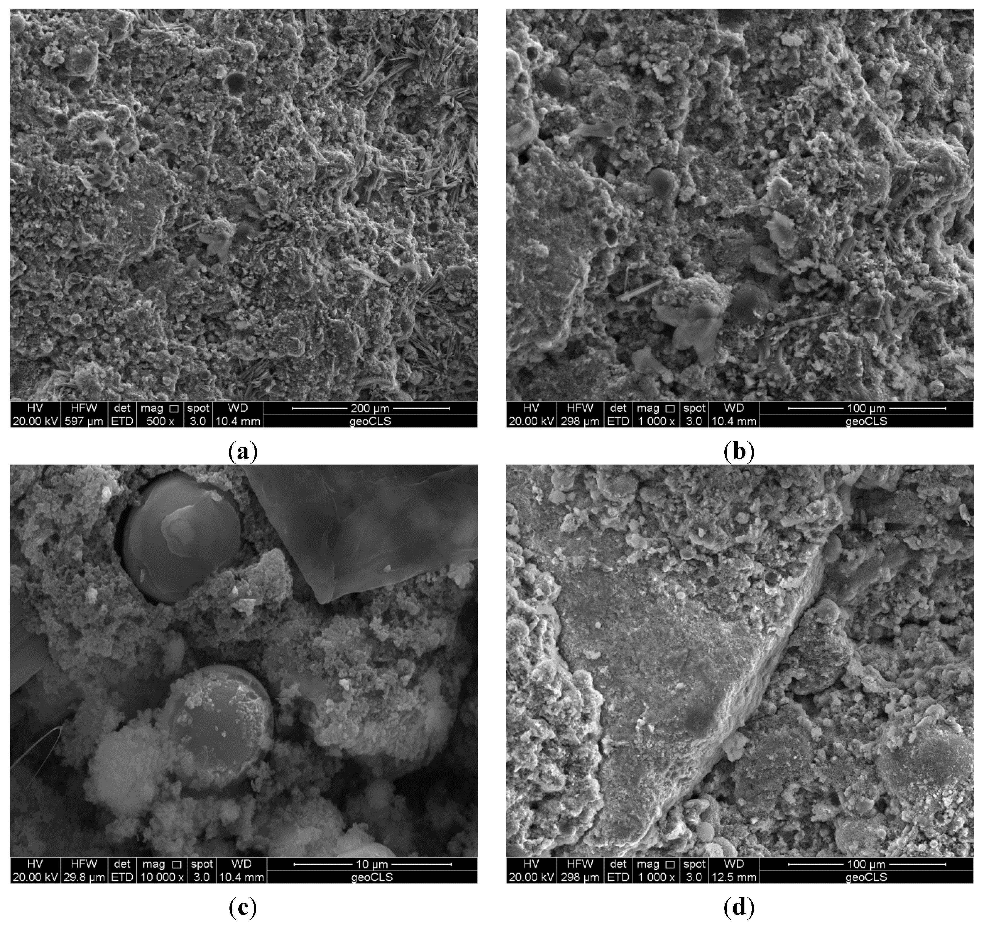
For the geopolymeric concrete G, assessment of geopolymerization process can be proven by the analysis of specimen microstructure, reported in the micrographs of Figure 13, obtained for different magnification values.
The microstructure composed of aggregates and geopolymerization reaction products (Figure 13a,b) is visible. Some unreacted fly ash particles, maintaining their spherical shape within the geopolymer microstructure, can be observed for a large magnification value in Figure 13c. Finally, a coarse aggregate within the geopolymeric matrix is shown in Figure 13d. The reported micrographs show a typical geopolymer concrete microstructure [50].
Finally, the compressive strength (Rc), of cubic 5 × 5 × 5 cm3 geopolymer concrete specimens, before and after isothermal treatment at different temperatures, is reported in Figure 14. Each value is obtained as the average of three measurements.
Figure 13. Geopolymer microstructure obtained by scanning electron microscopy (SEM) analysis: (a) 500×; (b) 1000× geopolymerization products; (c) 10,000×; and (d) 1000× coarse aggregate.
Energies 07 05291 g013
Figure 14. Geopolymer concrete compressive strength Rc after isothermal treatments.
Energies 07 05291 g014
The compressive strength at room temperature is 21.70 MPa and it decreases slightly, after eight thermal cycles, to a value of 20.34 MPa at 423 K. In addition no spalling phenomena were observed for the specimens, probably due to the low free water content in the prepared geopolymer concrete. After the thermal treatment at 723 K again no spalling phenomena were observed. In addition the compressive strength value still reaches the remarkable value of 15.00 MPa.
As concerns transient behavior simulations, the same approach followed for reference benchmarks has been applied to lightweight concretes and geopolymeric concrete. No qualitative differences were observed for tested materials in dynamic behavior passing from constant Vtot criterion to constant Qnom criterion, thus the latter will not be discussed further. The results, summarized in Table 7, are similar due to the homogeneous nature of prepared mixtures, as visible in Figure 11.
Table 7. Analysis results at constant Vtot for developed materials.
Materialmsol (kg)ΔTeff (K)Vtot × 103 (m3)Qeff (kW·hth)Qnom (kW·hth)ηstorage (%)Volume power density (kW·hth/m3)Power density (kW·hth/ton)
PA012.7438.496.400.0980.10295.8615.317.69
PA1011.6537.876.400.0910.09694.6314.227.81
PA2010.7236.586.400.0830.09190.9412.977.74
PA309.2435.026.400.0710.08187.6611.097.69
G11.0237.116.400.0850.09292.4213.287.71
These five materials showed good performances in terms of maximum average temperature reached during charge phase, better than PC and HT, and slightly better than CC. Simulation results confirm that the ΔTeff decreases, as expected, due to increasing plastic aggregate percentage in the concretes. As a consequence, ηstorage decreases too, passing from 95.86% for PA0 to 87.66% for PA30. However, it can be observed that they are remarkably higher than efficiency calculated for PC, HT and CC. An analogous conclusion is valid in terms of power densities, in fact, for above mentioned reference benchmarks, calculated power density is about 7.5 kW·hth/ton, while for developed materials it is 7.7 kW·hth/ton, that is also higher than FC power density.
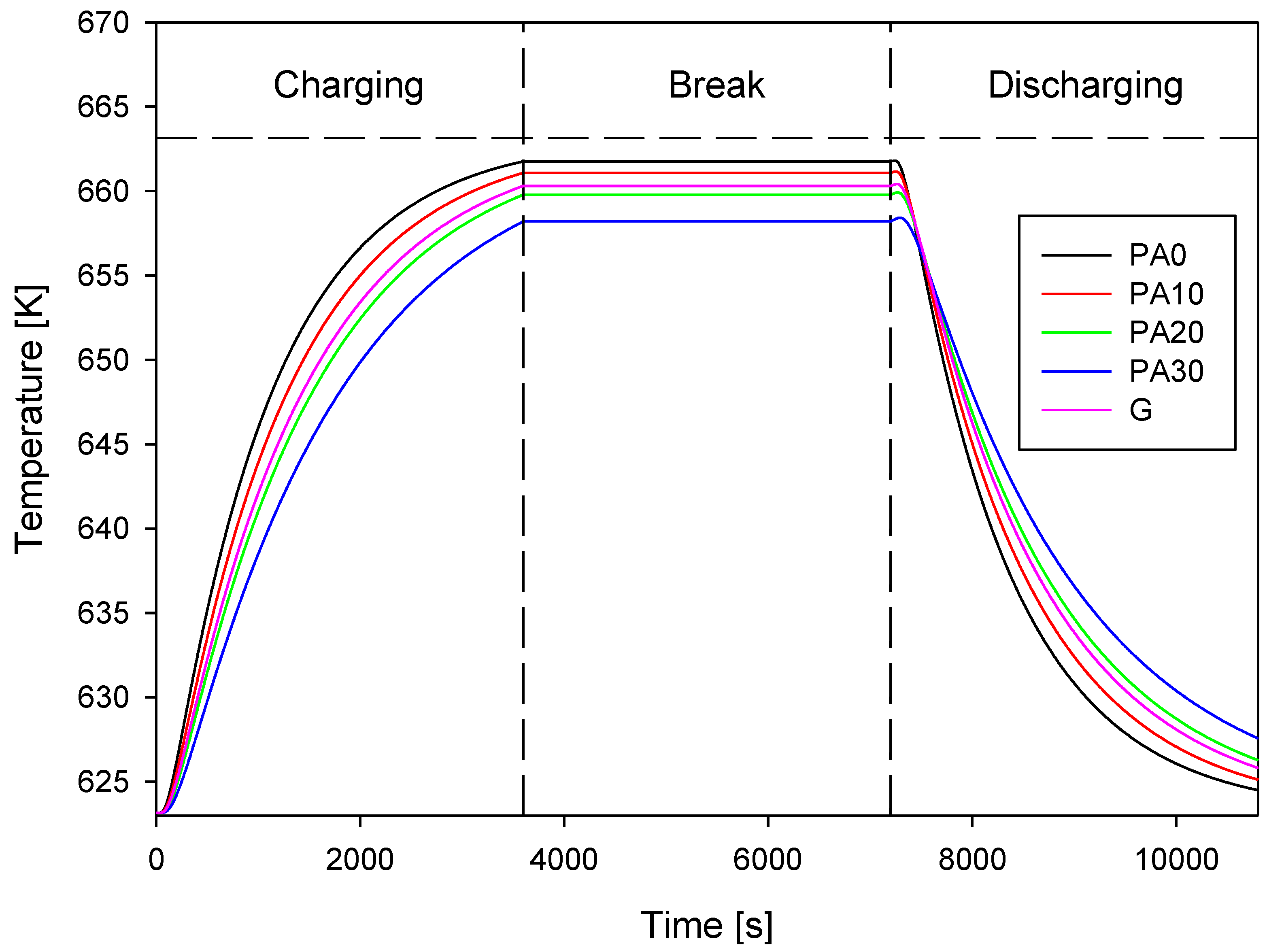
The average temperature profiles, at a distance da/2 from the center of inner tube, for constant Vtot criterion, are reported in Figure 15. The temperature profiles are very close because, as discussed before, Cvol and αsol of tested materials have been proven to be not so different.
The temperature profiles are ordered for increasing thermal diffusivity and agree with the constant volume analysis carried out in previous section for reference benchmarks. However, only a limited transient temperature raise, as response to the rapid HTF temperature change, can be observed at the beginning of the discharge phase. This is a noticeable difference when comparing these concretes with reference benchmarks, especially PC, HT and CC.
In Figure 16, the contour maps during the charging phase for developed mixtures are reported, to obtain the temperature field time evolution within the simulated elements.
Finally, it is worth noting that the geopolymeric concrete has a time evolution of the temperature contour between PA10 and PA20, because, as discussed before, their thermal properties are similar. Moreover, G, PC and HT have the same value of ksol but their dynamic behavior is very different. The geopolymeric concrete has no transient temperature raise, no relevant internal temperature gradients and a storage efficiency higher than that of PC and HT. These last two have higher effective thermal energy storage than geopolymeric concrete because their ρsol and csol values are higher. On the contrary, their ΔTeff is lower than G, because this attains a higher ηstorage so that, due to the geopolymer weight, a higher power density is achieved. The same is true when comparing G to CC and FC, even if the two reference benchmarks have a higher value of thermal conductivity.
Figure 15. Temperature profile at distance da/2 for developed materials, constant Vtot.
Energies 07 05291 g015
Figure 16. Temperature contour maps at constant Vtot for tested materials, charge phase.
Energies 07 05291 g016
PA0 shows a remarkable dynamic behavior and temperature distribution, due to a high thermal diffusivity, while a large use of plastic aggregate worsens the thermal behavior of developed material. A value in the range of 10%–20% of plastic aggregate seems to be the best for obtaining an acceptable transient behavior and a sustainable economic storage material by using a recycled aggregate from waste-plastic. Higher percentage of plastic aggregates resulted in poor thermal properties and so a non-satisfying dynamic behavior for a storage element. In Figure 17, the contour maps during the discharging phase for the five developed mixtures are reported.
Figure 17. Temperature contour maps at constant Vtot for tested materials, discharge phase.
Energies 07 05291 g017
All the thermal cycles seem to be almost reversible and without large internal gradients, which, as discussed in previous section, would indicate a sensibly slower heat transfer dynamic in the solid media and the major sources of thermal stresses for the storage element. Further, these numerical results demonstrate that the tested geopolymeric concrete is an eligible solid medium for SHTES because it performs with a high storage efficiency and a high power density, compared to storage materials retrieved from the literature.

4. Conclusions

In this work, thermal property data from the literature and experimentally measured, have been used in FEM-based simulations to evaluate the suitability of different concretes for TES applications. Further, thermal properties at high temperature, non-approximated geometry of the differential storage element and actual operating storage cycle have been concurrently taken into consideration.
The numerical results presented in this work, coupled with calculated values of ηstorage and power densities, are very useful during SHTES system design to discern storage material behavior under dynamic conditions. For instance, when a constant Vtot criterion is used, simulation results demonstrate that a conventional PC attains better performances than sophisticated storage materials such as CC and HT. Only the A4 provides the best performances in all cases, and it stands out as the top benchmark for comparative analysis. In fact, it has the highest heat storage efficiency, 96.51% at constant Vtot and 97.93% at constant Qnom, the highest power density and thus the minimum material weight to realize the entire module, starting from the studied differential storage element.
The selection of the storage material for a SHTES module cannot be based only on the value of solid medium thermal conductivity, but a thermal analysis is required to evaluate the dynamic behavior and an optimum balance between capacitive and heat transport behavior is required to the solid medium. If different design criteria are used, simulation results show that, for the same materials investigated, some differences in the thermal behavior, and hence performance emerge. The awareness of these different performances is not known a priori when selecting storage materials for SHTES module design. A correct simulation approach must be used to envisage such transient behaviors, in order to choose the best storage material to satisfy design specifications and to reduce costs.
Moreover, at the end of the charge phase, temperature contour maps, obtained from dynamic simulations, showed internal gradient and non-uniform temperature distribution for PC, HT and FC when the HTF temperature rapidly changes from charge phase to discharge phase. In a real module, thermal gradients can lead to undesired cyclic thermal stresses in the storage materials, so that they must be avoided to prevent decrease of thermo-mechanical properties.
Simulation results have demonstrated that the prepared materials have contributed to reduce material weight and to increase the specific heat capacity. In fact temperature contour maps and temperature profiles showed a good dynamic behavior and limited temperature gradients with respect to some benchmarks.
Especially for the geopolymeric concrete prepared and preliminarily characterized in this work, the comparative analysis with reference benchmarks has demonstrated that its thermal performances are very interesting for SHTES, because storage efficiency and power density are higher than that of cementitious composites like HT, CC and FC, or a conventional concrete, such as PC. Moreover, it has shown a remarkable mechanical stability at high temperature, also for repeated thermal cycles. In conclusion, these results confirm that geopolymeric concretes represent a sustainable alternative to conventional concrete as solid media for TES applications.

Nomenclature

c
specific heat capacity (J/(kg·K))
k
thermal conductivity (W/(m·K))
Cvol
volumetric heat capacity (kW·h/(m3·K))
PA0–30
concrete mixture (subscript from 0 to 30 indicate the percentage of plastic aggregate)
G
geopolymer
T
temperature (K)
t
time (s)
Q
thermal energy (kW·h)
m
weight (kg)
V
volume (m3)
di
inner tube diameter (m)
da
distance between center of two parallels tube (m)
L
length (m)
W
width (m)
H
height (m)
ΔT
temperature difference (K)

Greek Symbols

ρ
density (kg/m3)
α
thermal diffusivity (m2/s)
η
heat storage efficiency (%)

Subscripts

0
initial
f
final
tot
total
nom
nominal
eff
effective
th
thermal
sol
solid

Author Contributions

Raffaele Cioffi proposed the use of concretes with recycled-plastic aggregates and geopolymeric concretes for TES purpose and supervised all research activities in order to demonstrate the benefits of these materials. Claudio Ferone and Francesco Colangelo focused on materials mix design, specimens preparation, thermal characterization and SEM analysis in order to determine the thermophysical properties of interest for TES. Rosa di Maggio contributed by developing the procedure for the geopolymeric concrete thermal treatments and by dealing with the results discussion in order to refine the comparative analysis. Domenico Frattini was addressed to literature benchmarks selection, numerical model and simulation approach development, numerical analysis and post-processing. Finally, Giuseppina Roviello coordinated experimental activities and greatly helped during manuscript revision process in order to refine English forms and to reply to referees’ comments.

Conflicts of Interest

The authors declare no conflict of interest.

References

  1. Gil, A.; Medrano, M.; Martorell, I.; Làzaro, A.; Dolado, P.; Zalba, B.; Cabeza, L.F. State of the art on high temperature thermal energy storage for power generation. Part 1—Concepts, materials and modellization. Renew. Sustain. Energy Rev. 2010, 14, 31–55. [Google Scholar]
  2. Medrano, M.; Gil, A.; Martorell, I.; Potau, X.; Cabeza, L.F. State of the art on high temperature thermal energy storage for power generation. Part 2—Case studies. Renew. Sustain. Energy Rev. 2010, 14, 56–72. [Google Scholar]
  3. Kuravi, S.; Trahan, J.; Goswami, D.Y.; Rahman, M.M.; Stefanakos, E.K. Thermal energy storage technologies and systems for concentrating solar power plants. Prog. Energy Combust. Sci. 2013, 39, 285–319. [Google Scholar] [CrossRef]
  4. Tatsidjodoung, P.; Le Pierrès, N.; Luo, L. A review of potential materials for thermal energy storage in buildings applications. Renew. Sustain. Energy Rev. 2013, 18, 327–349. [Google Scholar] [CrossRef]
  5. Winter, C.J.; Sizmann, R.L.; Vant-Hull, L.L. Solar Power Plants; Springer-Verlag: Berlin, Germany, 1991. [Google Scholar]
  6. Laing, D.; Bahl, C.; Bauer, T.; Fiss, M.; Breidenbach, N.; Hempel, M. High-temperature solid-media thermal energy storage for solar thermal power plants. IEEE Proc. 2012, 100, 516–524. [Google Scholar] [CrossRef]
  7. Laing, D.; Bahl, C.; Bauer, T.; Lehmann, D.; Steinmann, W.D. Thermal energy storage for direct steam generation. Sol. Energy 2011, 85, 627–633. [Google Scholar] [CrossRef]
  8. Laing, D.; Lehmann, D.; Bahl, C. Comcrete storage for solar thermal power plants and industrial process heat. In Proceedings of the 3rd International Renewable Energy Storage Conference (IRES III 2008),, Berlin, Germany, 24–25 November 2008.
  9. Laing, D.; Steinmann, W.D.; Tamme, R.; Richter, C. Solid media thermal storage for parabolic trough power plants. Sol. Energy 2006, 80, 1283–1289. [Google Scholar] [CrossRef]
  10. Skinner, J.E.; Strasser, M.N.; Brown, B.M.; Selvam, R.P. Testing of high-performance concrete as a thermal energy storage medium at high temperatures. J. Sol. Energy Eng. 2013, 136. [Google Scholar] [CrossRef]
  11. John, E.E.; Hale, W.M.; Selvam, R.P. Concrete as a thermal energy storage medium for thermocline solar energy storage systems. Sol. Energy 2013, 96, 194–204. [Google Scholar] [CrossRef]
  12. Guo, C.; Zhu, J.; Zhou, W.; Chen, W. Fabrication and thermal properties of a new heat storage concrete material. J. Wuhan Univ. Technol. Mater. Sci. Ed. 2010, 25, 628–630. [Google Scholar] [CrossRef]
  13. Yuan, H.W.; Lu, C.H.; Xu, Z.Z.; Ni, Y.R.; Lan, X.H. Mechanical and thermal properties of cement composite graphite for solar thermal storage materials. Sol. Energy 2012, 86, 3227–3233. [Google Scholar] [CrossRef]
  14. Bai, F.; Xu, C. Performance analysis of a two-stage thermal energy storage system using concrete and steam accumulator. Appl. Therm. Eng. 2011, 31, 2764–2771. [Google Scholar] [CrossRef]
  15. Steinmann, W.D.; Buschle, J. Analysis of thermal storage systems using modelica. In Proceedings of the 4th International Modelica Conference, Hamburg, Germany, 7–8 March 2005; pp. 331–337.
  16. Selvam, R.P.; Castro, M. 3D FEM model to improve the heat transfer in concrete for thermal energy storage in solar power generation. In Proceedings of the ASME 2010 4th International Conference on Energy Sustainability, Phoenix, AZ, USA, 17–22 May 2010; Volume 2, pp. 699–707.
  17. Tamme, R.; Laing, D.; Steinmann, W.D. Advanced thermal energy storage technology for parabolic trough. J. Sol. Energy Eng. 2004, 126, 794–800. [Google Scholar]
  18. Arpino, F.; Massarotti, N.; Mauro, A.; Muoio, R.; Vanoli, L. Modeling of thermal energy storage: A review of different systems. In Proceedings of the 3rd International Conference on Computational Methods for Thermal Problems, Lake Bled, Slovenia, 2–4 June 2014.
  19. Frattini, D.; Ferone, C.; Colangelo, F.; de Pertis, M.; Cioffi, C. Computational evaluation of different construction materials performance in thermal energy storage systems. In Proceedings of the 3rd International Conference on Computational Methods for Thermal Problems, Lake Bled, Slovenia, 2–4 June 2014.
  20. Caverzan, A.; Cadoni, E.; di Prisco, M. Tensile behavior of high performance fibre-reinforced cementitious composites at high strain rates. Int. J. Impact Eng. 2012, 45, 28–38. [Google Scholar] [CrossRef]
  21. Corinaldesi, V.; Moriconi, G. Durable fiber reinforced self-compacting concrete. Cem. Concr. Res. 2004, 34, 249–254. [Google Scholar] [CrossRef]
  22. Zhang, J.; Gong, C.; Guo, Z.; Zhang, M. Engineered cementitious composite with characteristic of low drying shrinkage. Cem. Concr. Res. 2009, 39, 303–312. [Google Scholar] [CrossRef]
  23. Fernandez, A.I.; Martìnez, M.; Segarra, M.; Martorell, I.; Cabeza, L.F. Selection of materials with potential in sensible thermal energy storage. Sol. Energy Mater. Sol. Cells 2010, 94, 1723–1729. [Google Scholar] [CrossRef]
  24. Navarro, M.E.; Martìnez, M.; Gil, A.; Fernàndez, A.I.; Cabeza, L.F.; Olives, R.; Py, X. Selection and characterization of recycled materials for sensible thermal energy storage. Sol. Energy 2012, 107, 131–135. [Google Scholar]
  25. Zabalza Bribián, I.; Valero Capilla, A.; Aranda Usón, A. Life cycle assessment of building materials: Comparative analysis of energy and environmental impacts and evaluation of the eco-efficiency improvement potential. Build. Environ. 2011, 46, 1133–1140. [Google Scholar]
  26. Flatt, R.J.; Roussel, N.; Cheeseman, C.R. Concrete: An eco material that needs to be improved. J. Eur. Ceram. Soc. 2012, 32, 2787–2798. [Google Scholar] [CrossRef]
  27. Bignozzi, M.C. Sustainable cements for green buildings construction. Procedia Eng. 2011, 21, 915–921. [Google Scholar] [CrossRef]
  28. Cioffi, R.; Colangelo, F.; Montagnaro, F.; Santoro, L. Manufacture of artificial aggregate using MSWI bottom ash. Waste Manag. 2011, 31, 281–288. [Google Scholar] [CrossRef] [PubMed]
  29. Colangelo, F.; Cioffi, R. Use of cement kiln dust, blast furnace slug and marble sludge in the manufacture of sustainable artificial aggregates by means of cold bonding pelletization. Materials 2013, 6, 3139–3159. [Google Scholar] [CrossRef]
  30. Cioffi, R.; Maffucci, L.; Martone, G.; Santoro, L. Feasibility of manufacturing building materials by recycling a waste from ion exchange process. Environ. Technol. 1998, 19, 1145–1150. [Google Scholar] [CrossRef]
  31. Ferone, C.; Colangelo, F.; Cioffi, R.; Montagnaro, F.; Santoro, L. Use of reservoir clay sediments as raw materials for geopolymer binders. Adv. Appl. Ceram. 2013, 112, 184–189. [Google Scholar] [CrossRef]
  32. Andini, S.; Cioffi, R.; Colangelo, F.; Ferone, C.; Montagnaro, F.; Santoro, L. Characterization of geopolymer materials containing MSWI fly ash and coal fly ash. Adv. Sci. Technol. 2010, 69, 123–128. [Google Scholar] [CrossRef]
  33. Andini, S.; Cioffi, R.; Colangelo, F.; Grieco, T.; Montagnaro, F.; Santoro, L. Coal fly ash as raw material for the manufacture of geopolymer-based products. Waste Manag. 2008, 28, 416–423. [Google Scholar] [CrossRef] [PubMed]
  34. Ferone, C.; Colangelo, F.; Messina, F.; Santoro, L.; Cioffi, R. Recycling of pre-washed municipal solid waste incinerator fly ash in the manufacturing of low temperature setting geopolymer materials. Materials 2013, 6, 3420–3437. [Google Scholar] [CrossRef]
  35. Andini, S.; Montagnaro, F.; Santoro, L.; Accardo, G.; Cioffi, R.; Colangelo, F. Mechanochemical processing of blast furnace slag for its reuse as adsorbent. Chem. Eng. Trans. 2013, 32, 2299–2304. [Google Scholar]
  36. Bayasi, Z.; Zeng, J. Properties of polypropylene fiber reinforced concrete. ACI Mater. J. 1993, 90, 605–610. [Google Scholar]
  37. Kim, S.B.; Yi, N.H.; Kim, H.Y.; Kim, J.-H.J.; Song, Y.-C. Material and structural performance evaluation of recycled PET fiber reinforced concrete. Cem. Concr. Compos. 2010, 32, 232–240. [Google Scholar] [CrossRef]
  38. Sakulich, A.R. Reinforced geopolymer composites for enhanced material greenness and durability. Sustain. Cities Soc. 2011, 1, 195–210. [Google Scholar] [CrossRef]
  39. Ferone, C.; Colangelo, F.; Cioffi, R.; Montagnaro, F.; Santoro, L. Mechanical performances of weathered coal fly ash based geopolymer bricks. Procedia Eng. 2011, 21, 745–752. [Google Scholar] [CrossRef]
  40. Hussain, M.; Varley, R.J.; Cheng, Y.B.; Simon, G.P. Investigation of thermal and fire performance of novel hybrid geopolymer composites. J. Mater. Sci. 2004, 39, 4721–4726. [Google Scholar] [CrossRef]
  41. Kong, D.L.Y.; Sanjayan, J.G. Damage behavior of geopolymer composites exposed to elevated temperatures. Cem. Concr. Compos. 2008, 30, 986–991. [Google Scholar] [CrossRef]
  42. Kong, D.L.Y.; Sanjayan, J.G.; Sagoe-Crentsil, K. Factors affecting the performance of metakaolin geopolymers exposed to elevated temperatures. J. Mater. Sci. 2008, 43, 824–831. [Google Scholar] [CrossRef]
  43. Guerrieri, M.; Sanjayan, J.G. Behavior of combined fly ash/slag-based geopolymers when exposed to high temperatures. Fire Mater. 2010, 34, 163–175. [Google Scholar]
  44. Shaikh, F.U.A.; Vimonsatit, V. Compressive strength of fly-ash-based geopolymer concrete at elevated temperatures. Fire Mater. 2014. [Google Scholar] [CrossRef]
  45. Salomoni, V.A.; Majorana, C.E.; Giannuzzi, G.M.; Miliozzi, A.; di Maggio, R.; Girardi, F.; Mele, D.; Lucentini, M. Thermal storage of sensible heat using concrete modules in solar power plants. Sol. Energy 2014, 103, 303–315. [Google Scholar] [CrossRef]
  46. Ozger, O.B.; Girardi, F.; Giannuzzi, G.M.; Salomoni, V.A.; Majorana, C.E.; Fambri, L.; Baldassino, N.; di Maggio, R. Effect of nylon fibres on mechanical and thermal properties of hardened concrete for energy storage systems. Mater. Des. 2013, 51, 989–997. [Google Scholar] [CrossRef]
  47. Cement—Part 1: Composition, Specifications and Conformity Criteria for Common Cements; European Standard EN 197-1:2011; European Committee for Standardization (CEN): Brussels, Belgium, 2011.
  48. Aukour, F.J. Incorporation of marble sludge in industrial building eco-blocks or cement bricks formulation. Jordan J. Civ. Eng. 2009, 3, 58–65. [Google Scholar]
  49. Concrete—Part 1: Specification, Performance, Production and Conformity Criteria; European Standard UNI EN 206-1:2006; European Committee for Standardization (CEN): Brussels, Belgium, 2006.
  50. Fernandez-Jimenez, A.; Palomo, A. Nanostructure/Microstructure of Fly Ash Geopolymers. In Geopolymers: Structure, Processing, Properties and Industrial Applications; Provis, J.L., van Deventer, J.S.J., Eds.; CRC Press/Taylor and Francis: Boca Raton, FL, USA, 2009; pp. 89–117. [Google Scholar]