Abstract
The accurate information of the initial rotor position is very critical for successful starting of the Surface-mounted Permanent Magnet Synchronous Motor (SPMSM). In order to solve the problems of low accuracy and unreliability in the conventional estimation strategy, in this paper, an improved initial rotor position estimation strategy without any position sensor for SPMSM at standstill is proposed based on rectangular pulse voltage injection. In the work, when the second series of pulse voltages were applied. By the ways of strengthening the effect of weakening or strengthening magnetic fields and increasing the difference between each current of the vector. The improved strategy enhanced reliability and raised the initial position estimation accuracy from 7.5° to 1.875°. The improved strategy does not need any additional hardware. Experimental results demonstrate the validity and usefulness of the improved strategy.
1. Introduction
Permanent magnet synchronous Motors (PMSM) have been widely used in Electric Vehicles because of their advantages, such as high power density and high efficiency [1]. The PMSM has shown a continuous expansion in their share in traction and electric vehicle, wind power generation, compressors, full electric aircraft, and so on. The conventional PMSM drive systems always require the absolute rotor position information to exactly control the motor torque. In conventional drive systems, the problem of rotor position estimation is solved by using position sensors, such as a resolver or an encoder. However, there are many drawbacks in conventional drive systems, such as the limited speed, the higher cost, and the lower reliability of the system [2].
To solve this problem, the sensorless control technology has been attracting attention, and various studies have been published over the past two decades or so [3,4,5,6]. Rotor position and speed estimation techniques can be approximately classified into two main categories according to its principle of estimating rotor position: the back electromotive force (EMF) voltage estimation strategy [6,7,8] and saliency-based estimation strategy [9,10,11].
The first category relies on the estimation of the EMF induced by the rotor PM flux in the stator windings or on the estimation of the stator flux linkage by a proper dynamical model of the PMSM [12]. However, one of the most challenging topics for the EMF estimation strategy is the zero and very low speed position estimation. Due to the fact that the size of the back-EMF is proportional to the rotor speed it is, thereby, impossible to estimate initial rotor position when the PMSM is at standstill. Starting from inaccurate rotor position information may be accompanied by a temporary reverse rotation or may cause a starting failure [7].
The second category of rotor position and speed estimation techniques is based on the estimation of rotor anisotropy. Saliency exploitation is executed by means of a proper injection of additional signals, such as high-frequency signal injection [13]. The paper [14] shows good performance in the low-speed region, including zero speed under loaded condition. However, it is used in the interior PMSM (IPMSM). Since the d-q axis inductances are approximately equal and the salient effect is not obvious, the high-frequency voltage signal injection strategy cannot be applied to the sensorless control of a surface-mounted PMSM (SPMSM) at low and zero speed [15]. In order to accurately estimate the initial rotor position of SPMSM, papers [16,17] had proposed a pulse voltage vector injection strategy based on the magnetic saturation effect. The response currents, which are different from each other, are caused by the difference of the magnetic saturation due to the magnetic saliency. The voltage vector angle is required to be divided continuously for high-precision so that larger angle errors can be reduced to a certain value. Moreover, the identification of the magnetic pole may be wrong, owing to the extremely subtle difference of inductances between the N pole and S pole. The SPMSM rotates reversely when the judgment of the magnetic pole is wrong [18].
In this paper, an improved initial rotor position estimation strategy is proposed based on pulse voltage injection. The improved strategy increases the reliability of the conventional strategies of estimating rotor position. Based on the information of the estimated initial rotor position by injecting the first series of 12 pulse voltages, sufficiently large pulse currents are applied separately along the d-axis with the positive and negative direction. The improved strategy can significantly strengthen or weaken the magnetic field of the N/S pole, thereby enhancing the difference between inductances of the N and S pole and increasing the reliability of the initial rotor position estimation. In order to verify the improved estimation strategy, an experimental system of using a SPMSM has been setup and tested. During the estimation process, the rotor is practically at standstill. Experimental results indicated that the average of the estimation error is 1.5°, and the maximum estimation error is 1.875°. The improved strategy can not only accurately estimate the initial position of SPMSM, but also enhance the reliability of estimating results.
The aim of this paper is to provide an improved initial rotor position estimation strategy for SPMSM drives without a position sensor which are based on voltage vector injection. The paper is organized as follows. Section II describes the principle of the saturation saliency effect. A mathematical model of the SPMSM with saturation characteristics is established. Section III presents the design and implementation of accurate initial rotor position estimation and polarity estimation principles for the SPMSM, including the improved strategy of initial rotor position estimation. The finite element analysis and experimental results of the improved strategy for SPMSM drives are introduced in Section IV. Conclusions are given in Section V.
2. Saturation Saliency Effect and Model of SPMSM
2.1. The Principle of Saturation Saliency Effect
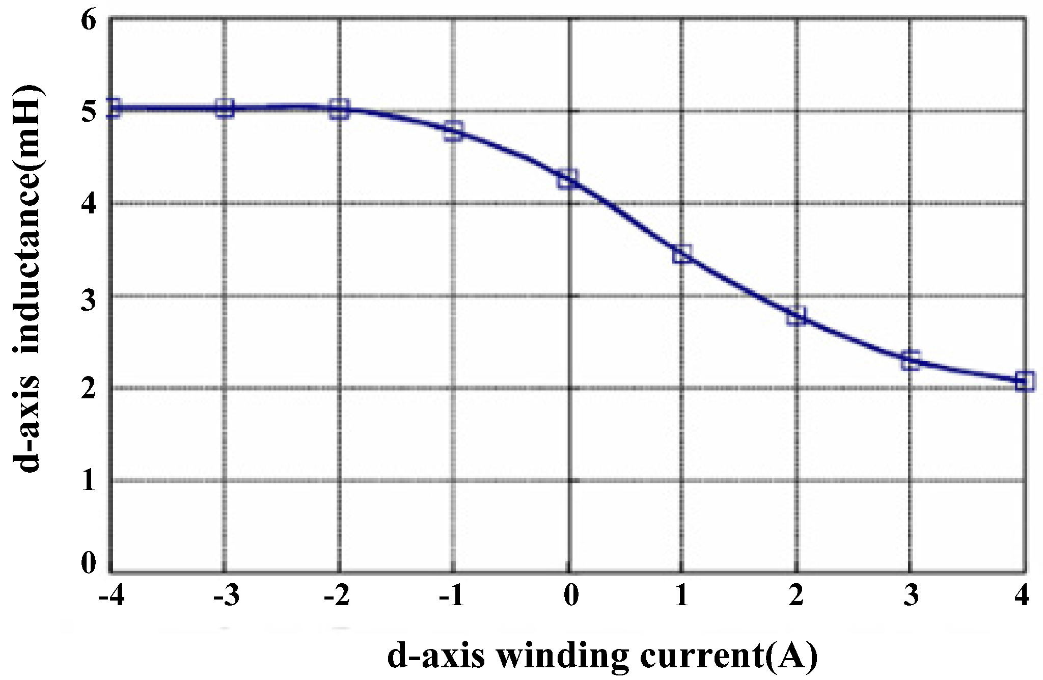
In SPMSM, the permeability of the permanent magnet is approximately equal to that of air. The fluxes of the d-axis and q-axis are mutually independent. In addition, , due to the magnetic circuits of the d-q axis, is identical. In order to increase the utilization ratio of magnetic fields, the SPMSM is designed close to the saturation condition [17]. When the air-gap flux raises to a certain extent, the stator core is saturated. Thus, the inductance of the d-axis decreases and the inductance saliency effect appears [18]. With the appearance of the saturation effect, the current of the stator winding increases, the saturation of stator core deepens, and the inductance of d-axis reduces [19]. The relationship between d-axis inductance and winding current is shown in Figure 1.
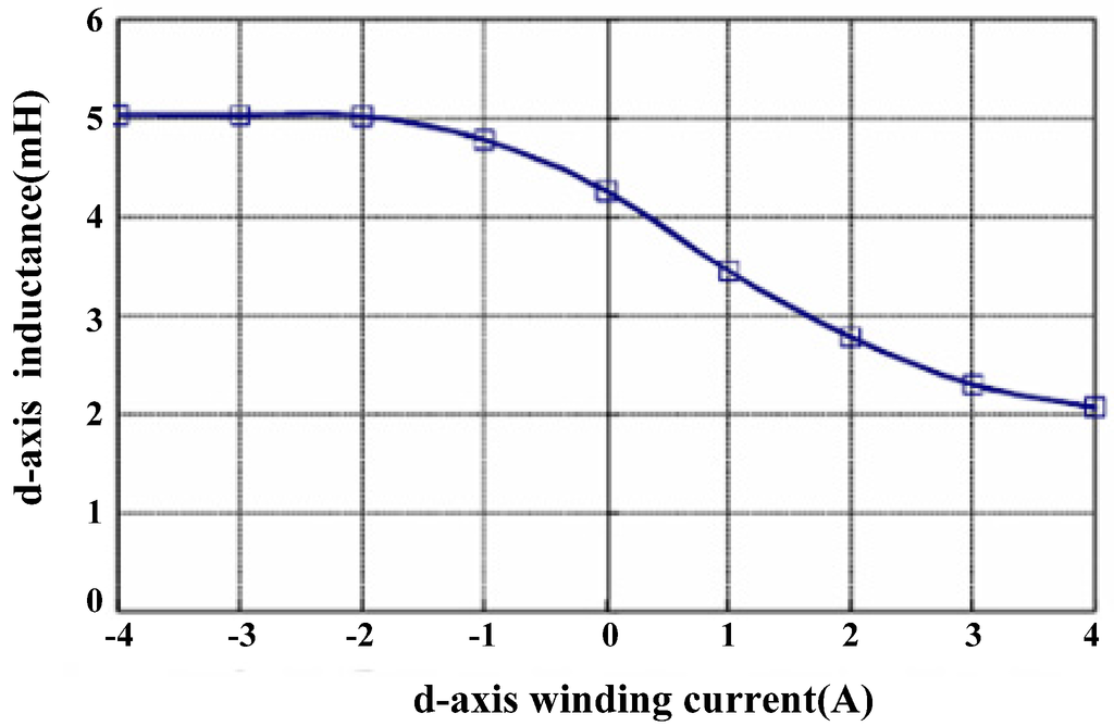
Figure 1.
The relationship between d-axis inductance and winding current.
Figure 1.
The relationship between d-axis inductance and winding current.
The magnetic potential by the permanent magnet generated can be equivalent to excitation current if. The ψ−i characteristic curve of the d-axis magnetic circuit is shown in Figure 2. The operating point of the d-axis magnetic circuit is determined by the excitation current if, As shown at point A, when injected into a constant forward-current, the d-axis magnetic circuit will be saturated. When introduced into a negative-current, the magnetic circuit is in linear segments [20]. In this paper, is set to the d-axis positive inductance; is set to the d-axis negative inductance, and the following formula can be obtained:
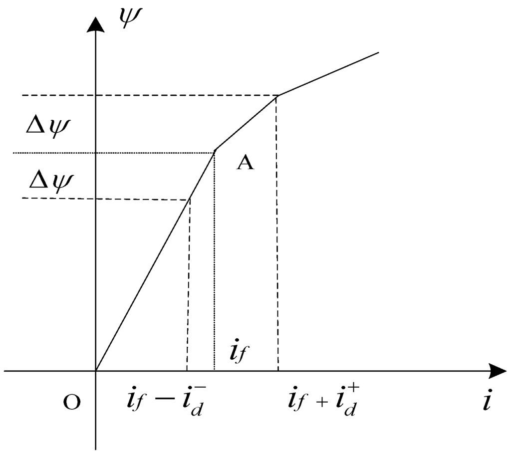
Figure 2.
Characteristic curve of d-axis magnetic circuit.
Figure 2.
Characteristic curve of d-axis magnetic circuit.

The ψ−i characteristic curve of q-axis magnetic circuit is as similar as d-axis magnetic circuit. The operating point is at the origin point, the magnetic circuit is in linear segments, and the saturation phenomenon is not generated. In this work, is set to the q-axis positive inductance; is set to the q-axis negative inductance, and the following formula can be obtained:
Due to the ψ−i characteristic curve of d-axis and q-axis are similar. is equal to , the following formula can be obtained:
2.2. Mathematical Model of a SPMSM with Saturation Characteristic
When estimating the initial rotor position, the rotor is stationary. Therefore, the effect of the rotating EMF in the mathematical model is ignored [21]. In order to analyze conveniently, the following assumptions are made in the derivation: three-phase stator windings of SPMSM are completely symmetrical, the induced EMF is ideal sinusoidal, eddy currents and hysteresis losses are negligible. And there is no damping winding on the rotor [22]. Figure 3 shows a schematic diagram of a PMSM.
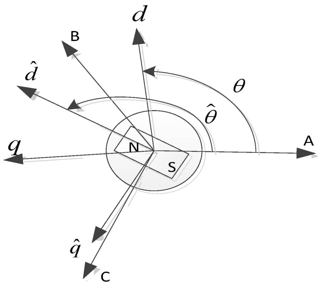
Figure 3.
Model of a SPMSM with definition of the used coordinates.
Figure 3.
Model of a SPMSM with definition of the used coordinates.

Positive voltage and negative voltage are applied along the d-axis. and will be influenced respectively by . The voltage equation in the d-q coordinate of SPMSM can be expressed as follows:
The amplitude of voltage vectors is very large and the action time of voltage vectors is very short, the Rs are negligible. The relationship between the current and voltage can be expressed as follows:
The angle between coordinate and coordinate varies with different coordinate. When varies, the same voltage vector is injected, different values of current response will be generated. This principle provides a theoretical basis for estimation the initial rotor position.
3. Design and Implementation of Initial Rotor Position Estimation Strategy
3.1. The Principle of Initial Rotor Position Estimation
The change in current in each phase can be measured during each pulse. Estimating the initial rotor position is accomplished by identifying the current response that is corresponds to the voltage vectors [23]. After voltage vectors are injected into the SPMSM, step responses will be generated in phase currents [24]. Three phase currents are combined in a current vector, step responses will be also generated by the current vector. The end time of the voltage vectors corresponds to the maximum of current vector in shown in Figure 4.
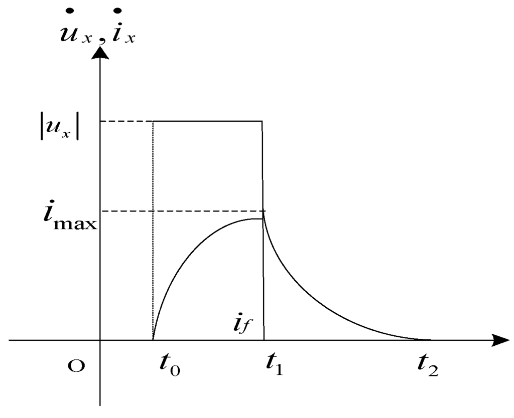
Figure 4.
Waveform of voltage and current vectors.
Figure 4.
Waveform of voltage and current vectors.

According to the principle of the saturation saliency effect, the d-axis flux of the stator core that corresponds to the magnetic pole of the rotor is very large [25], the saturated level of this portion is larger than other positions. The synchronization inductance reduces. When the voltage vectors are applied to the magnetic pole direction of the rotor as the voltage vector approaches the N pole, the d-axis current gradually increases because of the magnetic saturation, and the response of the current vector becomes faster. When the amplitude and duration of voltage vectors are same, the maximum of current vectors in the vicinity of the rotor poles increases. Therefore, voltage vectors in an electrical angle period are injected into the SPMSM. Obtaining a set of response maximums of current vectors, the electrical angle that corresponds to the maximum is the position of rotor magnetic pole. Thence, the initial rotor position can be estimated for the SPMSM. The control block diagram of initial position estimation is shown in Figure 5.

Figure 5.
Initial rotor position estimation diagram.
Figure 5.
Initial rotor position estimation diagram.
3.2. The Improved Strategy of Initial Position Estimation
When the rotor of the SPMSM is absolutely stationary, based on the analysis above. The followings are the assumptions on the initial rotor position estimation system:
(1) The hardware circuit of current estimation can accurately reflect the difference between the current vectors.
(2) Current vectors can obviously strengthen or weaken magnetic field when they are along the d-axis.
(3) The motor rotor is completely stationary.
When the estimation system meets the above three hypotheses, the initial rotor position can be estimated with high accuracy as long as the position of the voltage vector has been subdivided further. However, the current sampling system has noise interference, the system is impossible to completely and exactly distinguish tiny fluctuations of the armature current. This leads to the motor reversal since the polarity estimation has large errors.
Increasing the amplitude or the action duration of voltage vectors can deepen the inductance saturation and enhance the effect of strengthening or weakening the magnetic field. In this way, with the variation of angles, the difference between currents expands. Blindly increasing the current value would make the motor torque raise and drive the motor to rotate, thereby causing the initial position estimation to fail.
To solve this upper problem, the paper proposes an improved strategy. After estimating the initial rotor position with the second series of voltage vectors, voltage vectors that prolong the action time are applied along the positive and negative directions of the d-axis respectively, until peak values of current are so large that the effect of strengthening or weakening the magnetic field is obvious. The positive direction of the d-axis can be accurately identified. The angle is estimated based on in the first step. Voltage vectors in the positive direction are applied up and down of the estimated position at interval of 7.5°. Similarly, continue to subdivide the angle until the accuracy of the estimated angle meets the requirements.
3.3. Realization of Iitial Rotor Position Estimation for SPMSM
The improved estimation strategy is divided into three processes in this work. The flow chart of the estimation is shown in Figure 6.
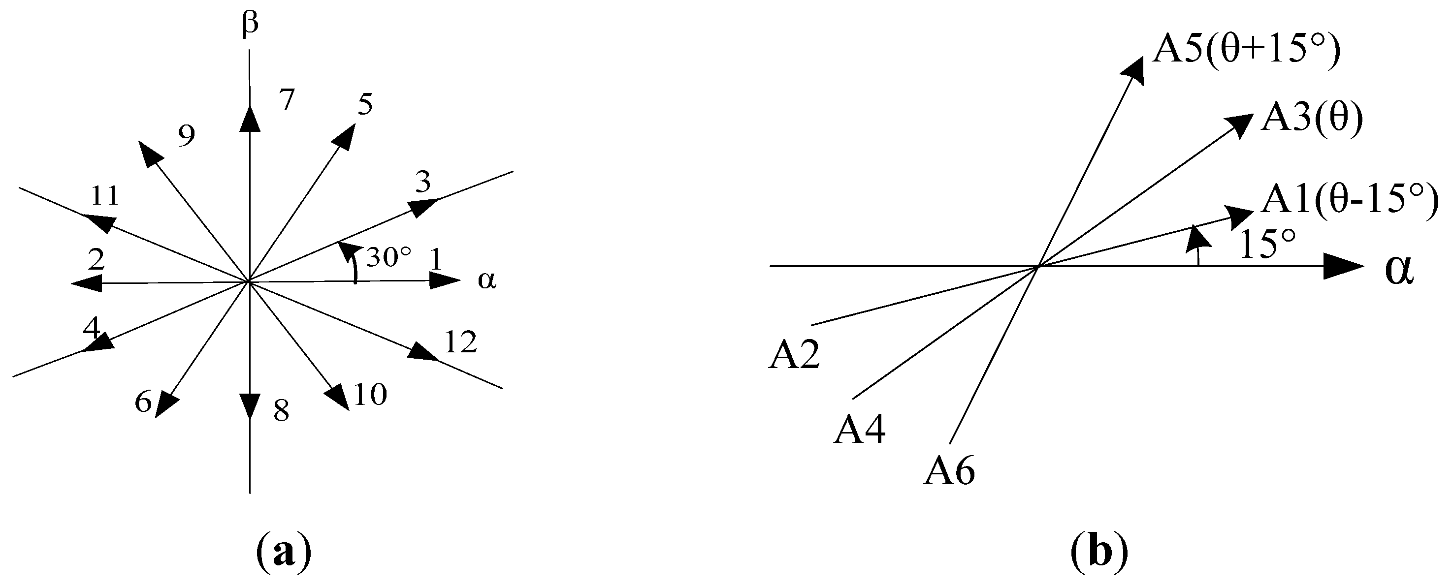
In the first process, 12 distinct voltage vectors are injected into the motor in numerical order (1-2-3-..-12) as shown in Figure 7a. Each voltage vector has the interval of 30° (electrical degrees) and retains the same action time. The current response of each voltage vector is calculated, obtaining the maximum of current responses . Select the maximum of recorded as . This moment, the rotor remains stationary every time the voltage vector is provided. All gate signals of the inverter are turned off to force each phase current to zero. The estimation error will smaller than ±15°.
In the second process, in Figure 7b, 6 distinct voltage vectors of the second series (A1–A6) are applied. The interval between each voltage vector is 15°. Based on the result of the first process, responses of current vector are calculated, obtained a set of new , picking the maximum of is compared with , the bigger number in the result is the new .
In the third process, the new estimated angle of the N-pole position can be obtained by similar way as the second process for these voltage vectors at interval of 7.5. Thus, the accuracy of the estimated angle is 1.875° in this stage. After that, continue to subdividing the angle until the precision of the estimated angle meets the requirements. The resulting angle that the latest corresponds to is the angle of the initial rotor position.
To decide the amplitude of the voltage vectors, the modulation factor m is introduced and it is defined as follows:
where is the amplitude of the voltage vector and is the DC source voltage of the inverter.

Figure 6.
Flow chart of the initial rotor position estimation.
Figure 6.
Flow chart of the initial rotor position estimation.
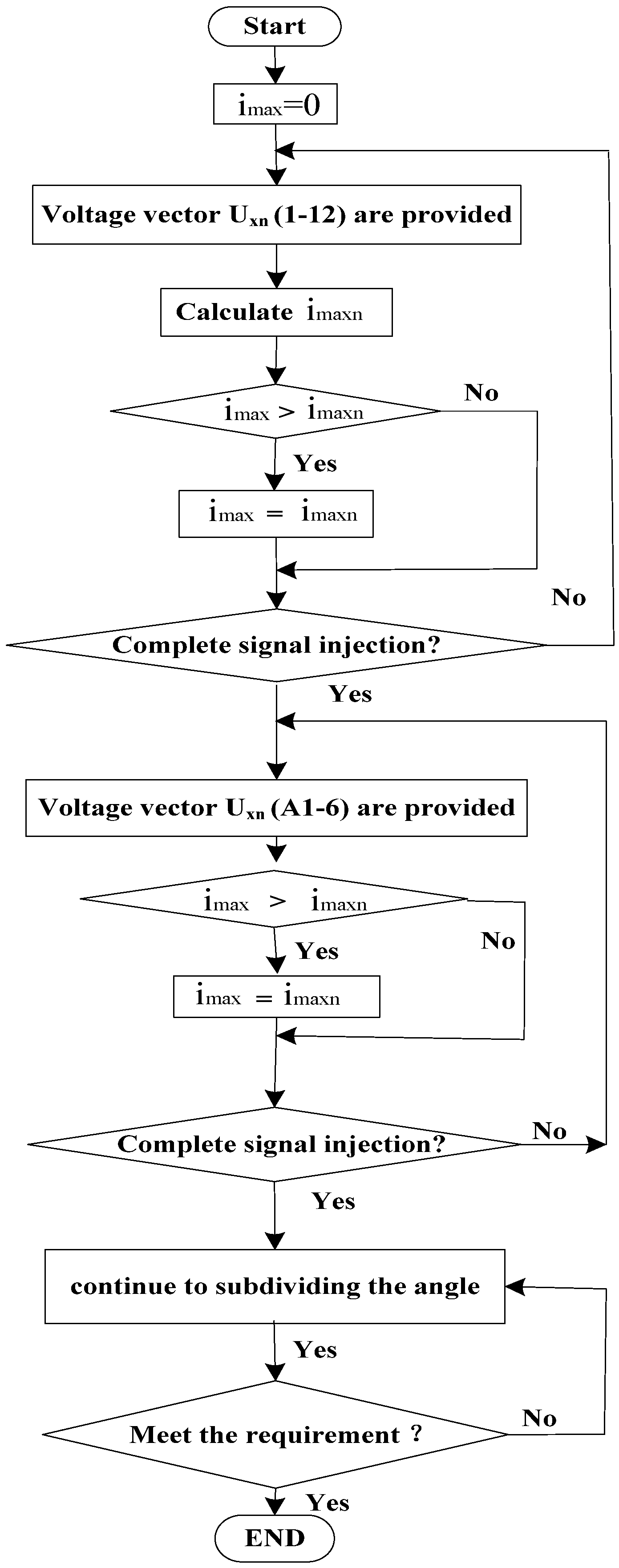

Figure 7.
(a) Voltage vectors used in the first process; and (b) Voltage vectors used in the second process.
Figure 7.
(a) Voltage vectors used in the first process; and (b) Voltage vectors used in the second process.
3.4. Sensorless Control of the SPMSM
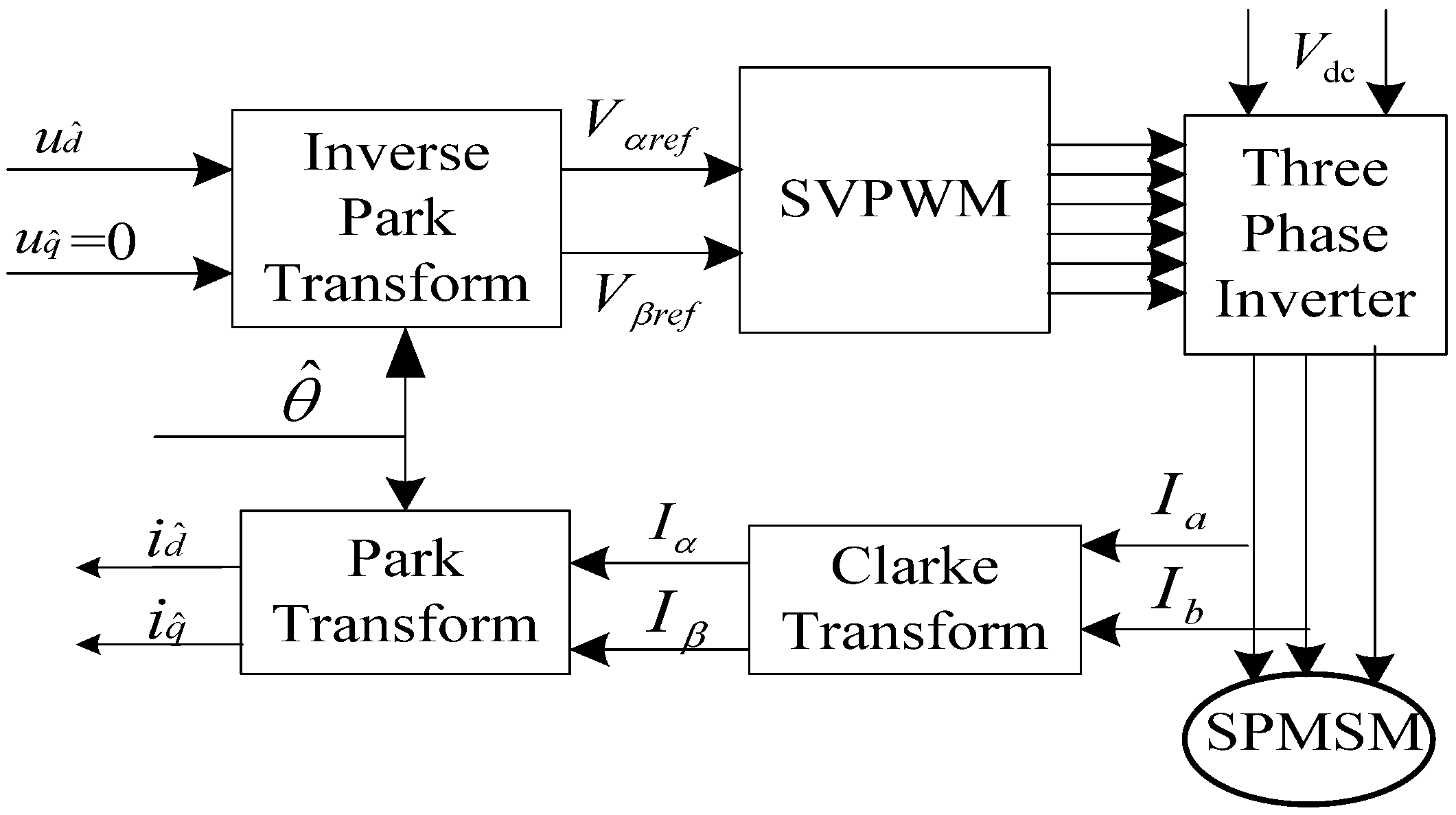
In this section, a sensorless speed control with initial rotor position estimation of the SPMSM is described. Figure 8 shows a block diagram for sensorless control of the SPMSM. After estimation the initial rotor position, using the I/F control scheme for starting and low speed operation of the SPMSM. When the speed of the motor reaches a certain frequency, there by realizing sensorless speed control of the SPMSM. When the SPMSM is at starting and low speed, switch two is in the #1 position in the Figure 8.
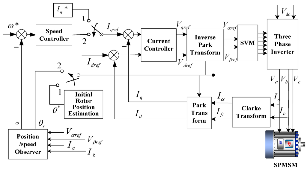
Figure 8.
Sensorless control operation block diagram of the SPMSM.
Figure 8.
Sensorless control operation block diagram of the SPMSM.

4. Experimental Results and Analysis
4.1. Finite Element Analysis and Simulation
Analyzing a SPMSM by using a soft software, SPMSM parameters of the simulation are presented in Table 1.

Table 1.
SPMSM parameters.
| Parameters | Values |
|---|---|
| Rated Power/kW | 17.8 |
| Rated voltage/V | 380 |
| Rated current/A | 30 |
| Rated speed/(r/min) | 1500 |
| Number of pole pairs | 2 |
| d-axis inductance/mH | 17 |
| q-axis inductance/mH | 17 |
| inertia of the rotating system/(kg·m2) | 0.0058 |
Current vectors of the corresponding voltage vectors in the N-pole (d-axis) direction of the rotor is shown in Figure 9a. Current vectors of the corresponding voltage vectors in the q-axis direction of the rotor is shown in Figure 9b.
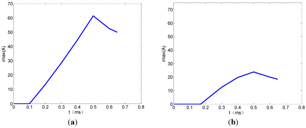
Figure 9.
Curve of current vector. (a) Curve of d-axis current vector; and (b) curve of q-axis current vector.
Figure 9.
Curve of current vector. (a) Curve of d-axis current vector; and (b) curve of q-axis current vector.

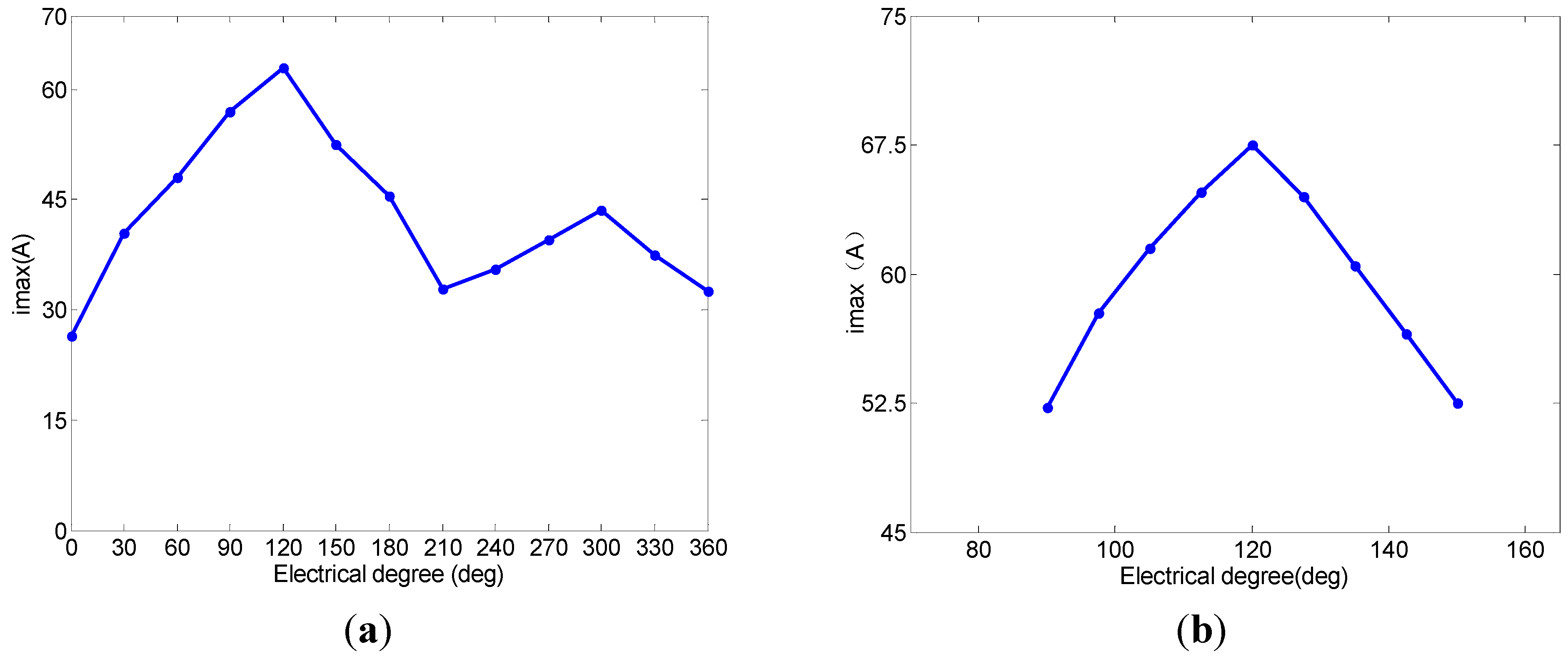
A series of voltage vectors are injected at 30° intervals from 0° to 360°. The phase current responses when voltage vectors are applied along the stator winding of the SPMSM are obtained. The maximum of each current vector is extracted, as shown in Figure 10. As is obvious from Figure 10a, the maximum of the current vector at 120° is the largest. That is to say, the d-axis direction is located in the vicinity of 120°. The maximum of the current vector at 210° is the minimum. Two peaks of the current vectors are shows in Figure 10a. The first is the current vector that corresponds to the N-pole direction of the rotor. The second is the current vector that corresponds to the S-pole direction of the rotor. The maximum of current vector responses after subdividing is shown in Figure 10b.
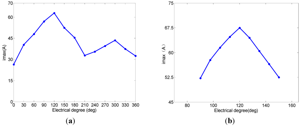
Figure 10.
(a) Maximum values of 0°–360° current vector response; and (b) Maximum values of current vector response after subdivided.
Figure 10.
(a) Maximum values of 0°–360° current vector response; and (b) Maximum values of current vector response after subdivided.
4.2. Experimental and Results Analysis
The initial rotor position estimation strategy of section III is tested on a SPMSM with rated parameters listed in Table 1. The experimental system for laboratory testing is shown in Figure 11. A high-performance digital signal processor (TMS320F2833) from Texas Instruments (Dallas, TX, USA) is used to implement the improved estimation strategy. In order to obtain the rotor position-related saliency information, a series of voltage pulses with high widths and short duty are injected into the stator windings. These voltage vectors are generated by three-phase voltage inverters in a drive system and no additional hardware is required.

Figure 11.
System configuration for the experimental. (a) Drive control platform; and (b) motor testing platform.
Figure 11.
System configuration for the experimental. (a) Drive control platform; and (b) motor testing platform.
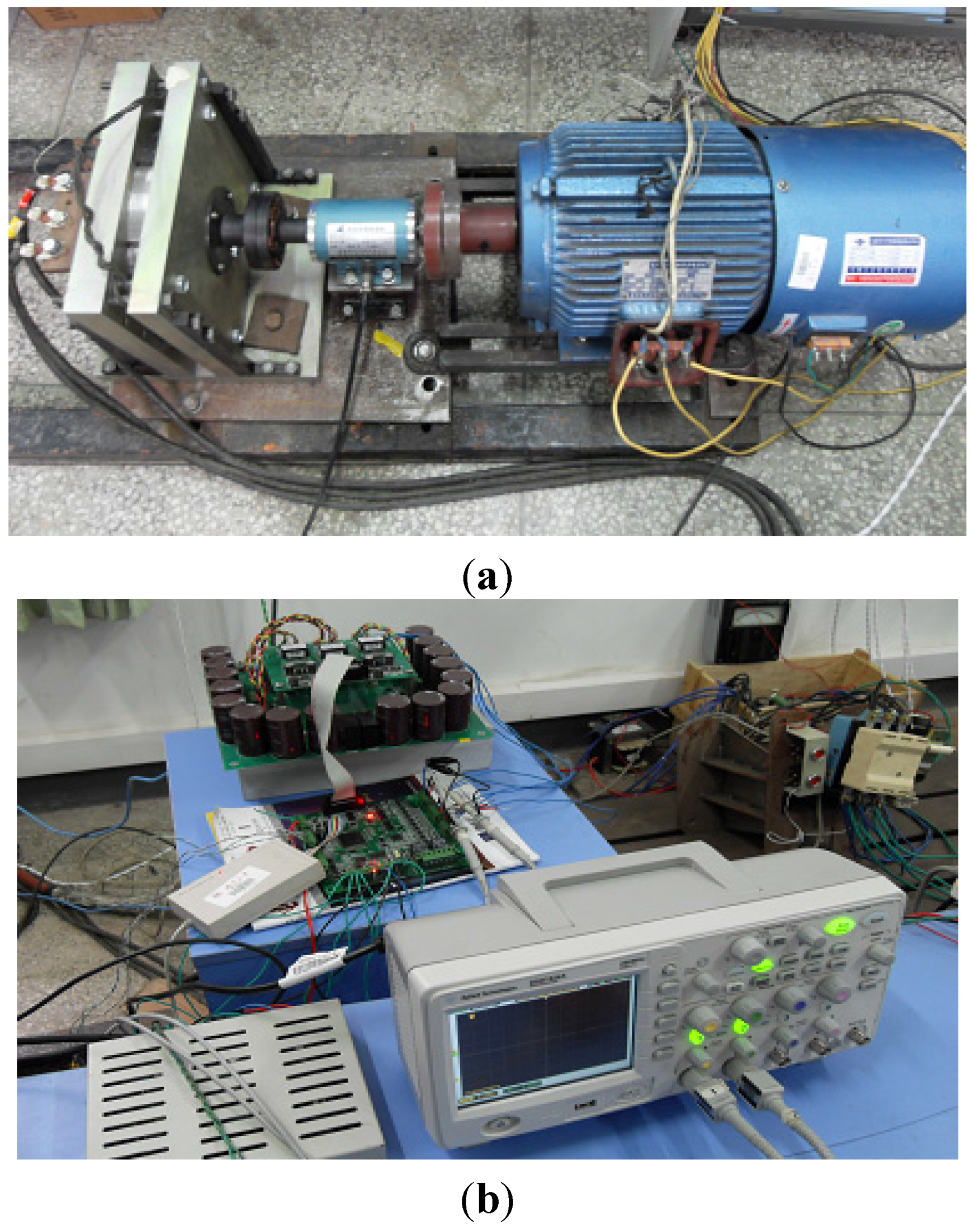
Figure 7a shows that, theoretically, voltage vector 9 is along the N pole of the rotor at this time and the value of the corresponding current is at the maximum. Figure 12a shows that voltage vector 10 is along the N pole of the d-axis and the corresponding current is at the maximum. Figure 12b shows the peak value chart of the d-axis currents of the second series of voltage vectors. The ordinate is the current per unit value and the current reference value is the rated current peak of 42.4 A. In Figure 12b, when the current peak value is 0.4 times the reference value, the current of the N pole is approximately equal to the S pole. Based on these, the effect of strengthening or weakening the magnetic field is not obvious; when the value of current is small, it may cause errors in the identification of N/S poles, increasing the action duration of voltage vectors to enhance the value of the current. However, oversize current values make the torque large enough to rotate the rotor. Hence, the traditional strategy has obvious drawbacks.
Figure 13 shows B phase currents in the first series of voltage vectors. With an increase of current peak, the difference between the current values of the S pole and the N pole that vector 9 and vector 10 respectively correspond to goes up and the difference between the peak values of the currents that the voltage vectors correspond to increases. This shows that heavy current is not only beneficial to enhance the effect of strengthening or weakening the magnetic field, but also conducive to distinguish the slight change of inductance.
Figure 14 shows the current waveform of the improved initial rotor position estimation strategy. The peak value of the current that voltage vector 22 corresponds to is significantly larger than that which voltage vector 21 corresponds to, illustrating that the judgment of the N pole by vector 9 and vector 10 is opposite. By injecting forward and reverse large currents, such as vector 21 and 22, the wrong judgment is corrected and the reliability of the initial rotor position estimation is guaranteed. In this paper, the experimental accuracy is 1.875°. The disparity between current vectors is more than 1 A and the accuracy of the estimation is very high.

Figure 12.
Current amplitude of the first series voltages. (a) 0.15 times the reference value; and (b) 0.4 times the reference value.
Figure 12.
Current amplitude of the first series voltages. (a) 0.15 times the reference value; and (b) 0.4 times the reference value.
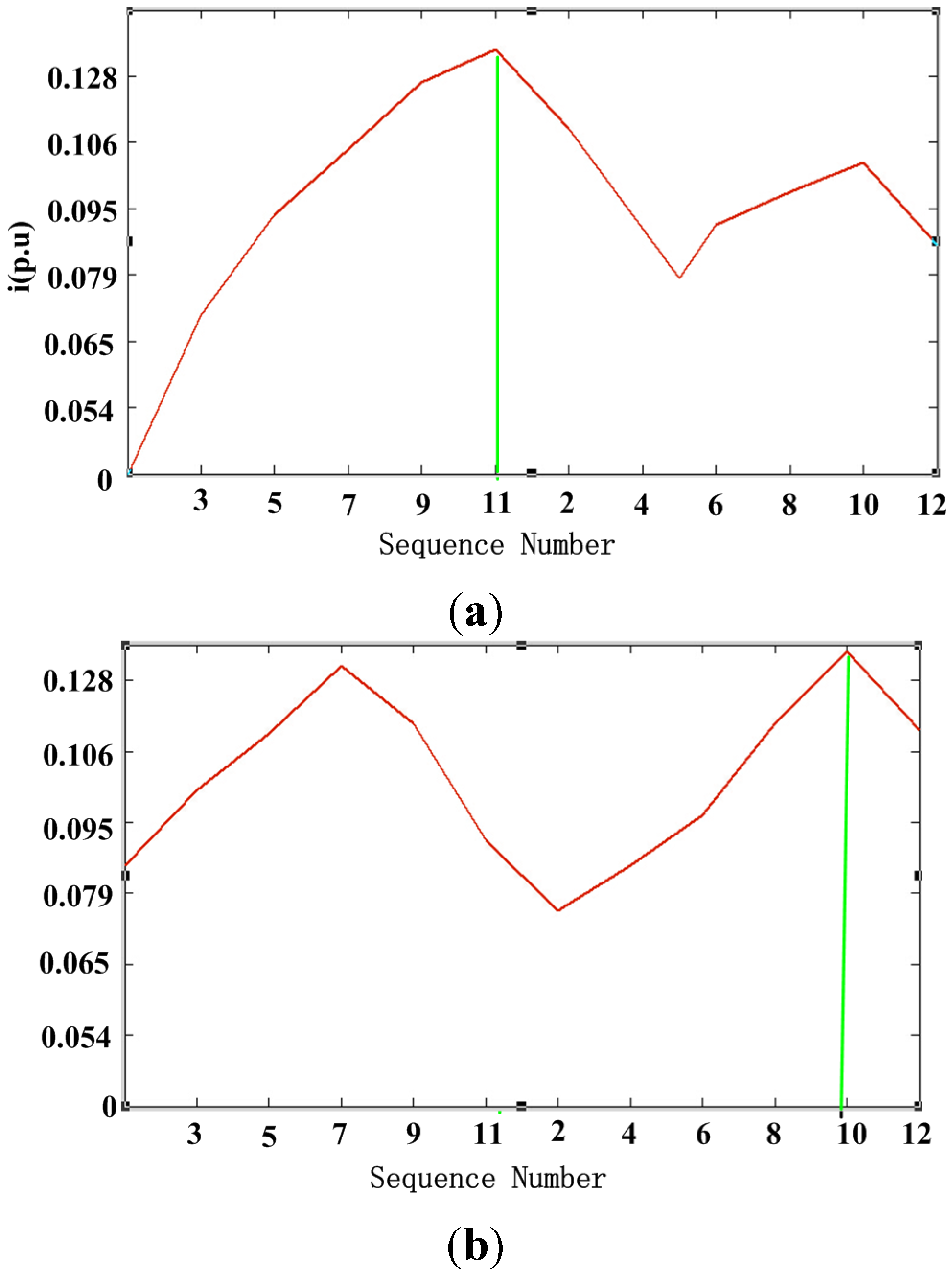

Figure 13.
Current of the first series voltages. 0.15 times the reference value.
Figure 13.
Current of the first series voltages. 0.15 times the reference value.
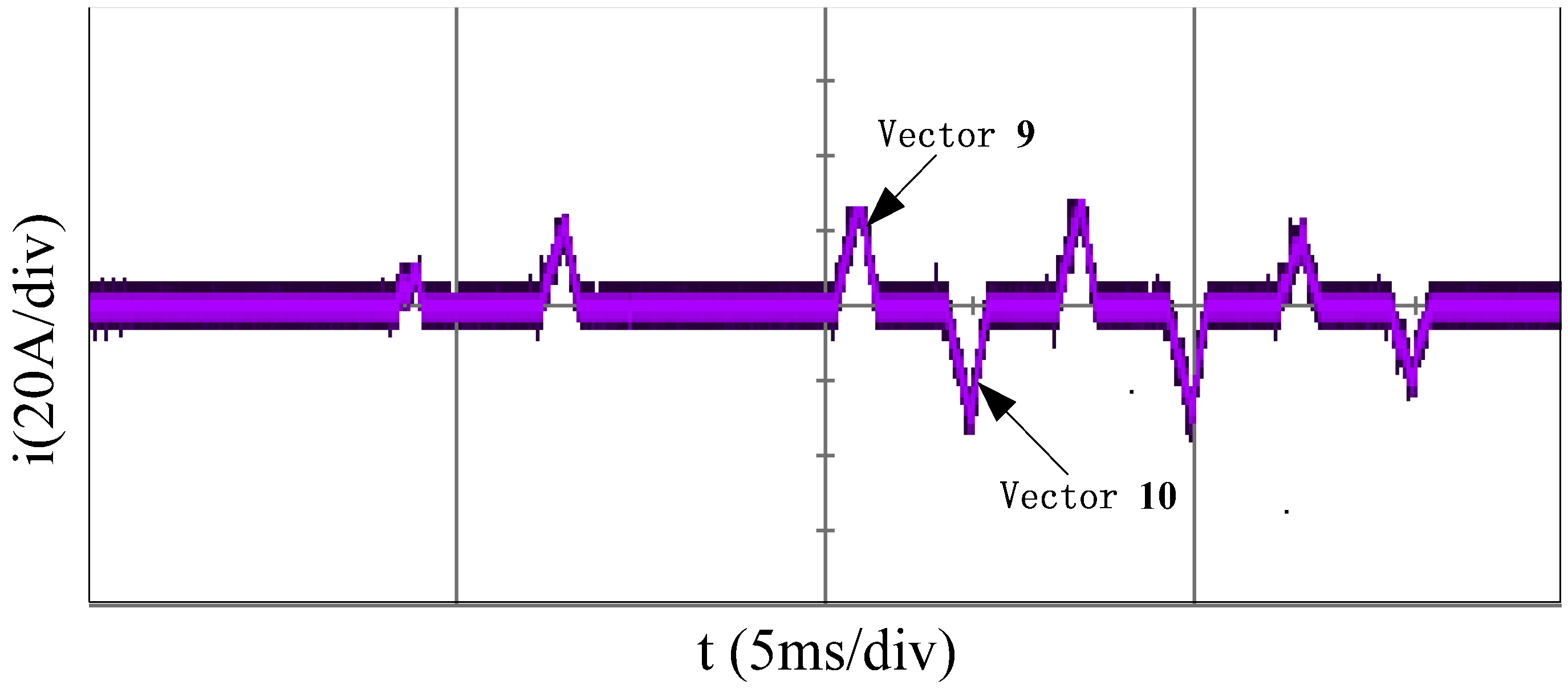
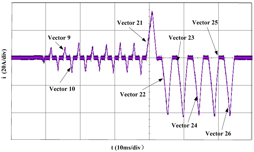
Figure 14.
Current of the improved initial position estimation.
Figure 14.
Current of the improved initial position estimation.

The pre- and post-improved estimation strategy are, respectively, used in 18 experiments. The experimental results are described as is shown in Figure 15. Results show that, before the improvement, in order to prevent the rotor rotating, the current value cannot be too large, resulting in the effect of strengthening or weakening magnetic field is not obvious for the estimated results are 120°. The results are totally opposite. The maximum deviation may be 15° when the result is 120° or 300°. The estimation accuracy is not high enough. After using the improved strategy, estimated results are stable around 300° and the deviations are within 3.75°. The improved strategy can obviously enhance the accuracy and reliability of initial position estimation.
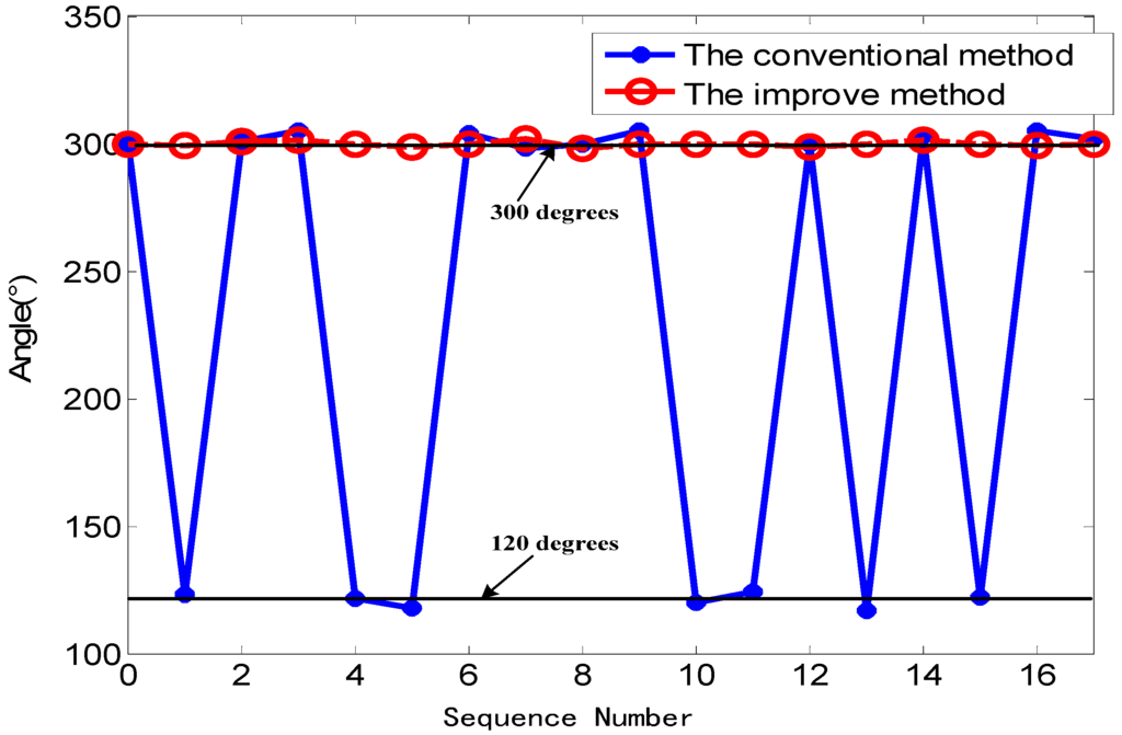
Figure 15.
Experimental results of initial electrical rotor position estimation error.
Figure 15.
Experimental results of initial electrical rotor position estimation error.

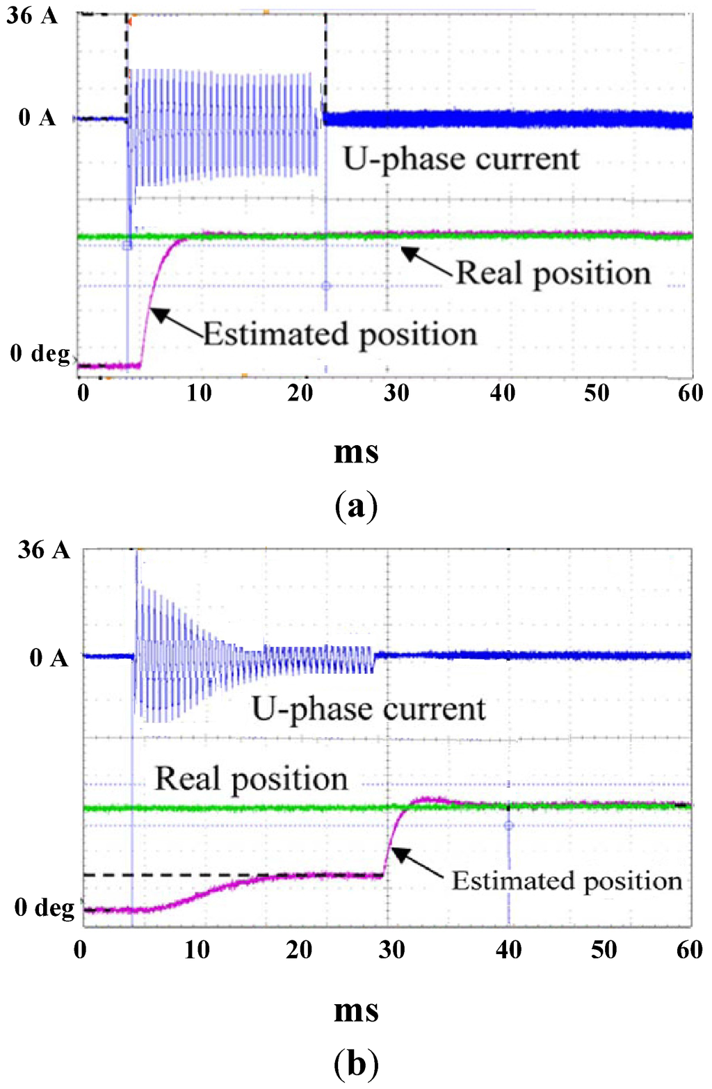
Figure 16.
Initial rotor position estimation. (a) Initial polarity is N pole; and (b) Initial polarity is S pole.
Figure 16.
Initial rotor position estimation. (a) Initial polarity is N pole; and (b) Initial polarity is S pole.

Figure 16 shows transient processes of the initial position estimation at standstill by experiment. Position signal output. When the initial polarity is N pole, the total estimation time as shown in Figure 16a. On the other hand, when the initial polarity is S pole, the estimation time as shown in Figure 16b. This case costs the longest estimation time of all the cases where the rotor is positioned from 0 up to 360 in mechanical degrees. Furthermore, this high-precision initial position estimation is confirmed to be repeated without any failure regardless of the initial rotor position.
Figure 17 shows the comparison between the actual and the estimated initial electrical rotor position. The estimation was performed at 50° intervals over the range from 0° to 360°. The comparison shows an excellent agreement and confirms the usefulness of the improved strategy. The maximum and average values of the error for the initial rotor position estimation are 5.4 and 1.4, respectively. The obtained values for initial rotor position are small for the purposes of the application.
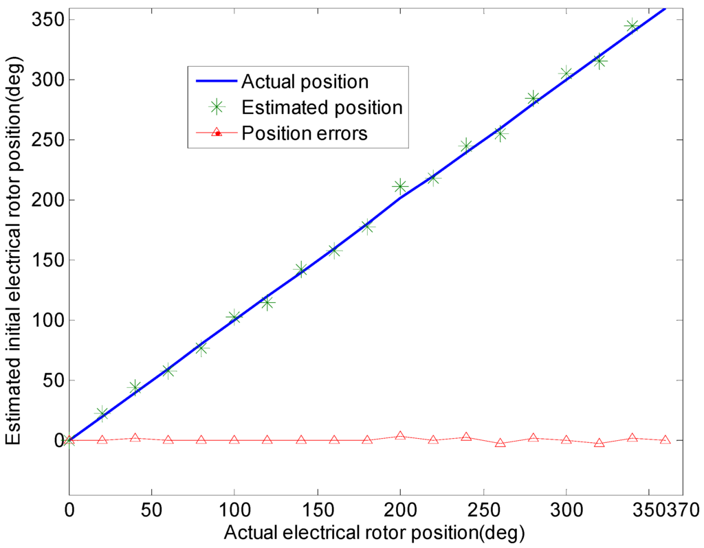
Figure 17.
Experimental results of initial electrical rotor position estimation.
Figure 17.
Experimental results of initial electrical rotor position estimation.

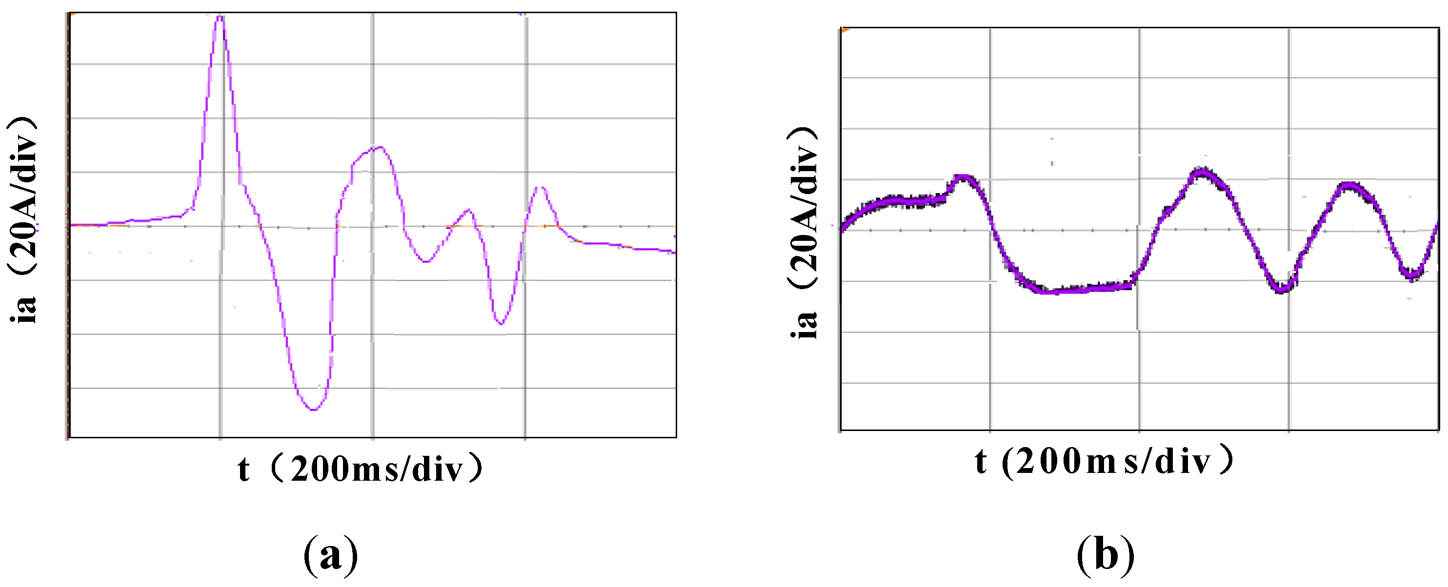
Figure 18a shows the starting currents when the identification of the rotor pole is inverse. Namely, the starting current is too large, and the SPMSM may fail to start. Figure 18b indicates the starting currents, when the improved strategy is used. The current is very smooth, and the SPMSM will start successfully.
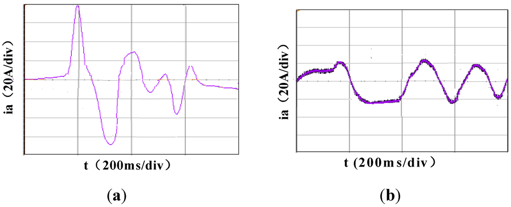
Figure 18.
Comparison of starting current waveform. (a) Incorrect judgment of the pole; and (b) correct judgment of the pole.
Figure 18.
Comparison of starting current waveform. (a) Incorrect judgment of the pole; and (b) correct judgment of the pole.
5. Conclusions
The conventional initial rotor position estimation strategies have some drawbacks, such as the identification of the N/S pole may be improper and the rotor position judgment may be wrong due to the difference between the inductances being small.
The paper proposed an improved initial rotor position estimation strategy. The validity of the improved strategy has been validated in experiments with a 17.8 kW SPMSM. It is experimentally confirmed that the improved strategy can not only raise the accuracy from 7.5° to 1.875° or initial position estimation, but also guarantee the rotor is at absolute standstill. Moreover, it was experimentally demonstrated that the improved strategy is suitable for both SPMSM and IPMSM.
Acknowledgments
The work was supported by the National Electric Power Conversion and Control Engineering Technology Research Center (Hunan University) and funded in part by the National Natural Science Foundation of China (61573133) and National High Technology Research and Development Program (2012BAH11F03). The authors gratefully acknowledge their support.
Author Contributions
Xuan Wu conceived the experiments. All authors assisted the project and contributed to writing the paper. All authors discussed the simulation results and approved the publication.
Conflicts of Interest
The authors declare no conflict of interest.
References
- Bai, J.; Liu, Y.; Sui, Y.; Tong, C.; Zhao, Q.; Zhang, J. Investigation of the cooling and thermal-measuring system of a compound-structure permanent-magnet synchronous machine. Energies 2014, 7, 1393–1426. [Google Scholar] [CrossRef]
- Zheng, P.; Tong, C.; Bai, J.; Sui, Y.; Song, Z.; Wu, F. Magnetic decoupling design and experimental validation of a radial-radial flux compound-structure permanent-magnet synchronous machine for HEVs. Energies 2012, 5, 4027–4039. [Google Scholar] [CrossRef]
- Wang, Z.; Niu, S.; Ho, S.L.; Fu, W.N.; Zhu, J.G. A position detection satrategy for sensorless surface mounted permanent magnet motors at low speed using transient finite element analysis. IEEE Trans. Magn. 2012, 48, 1003–1006. [Google Scholar] [CrossRef]
- Zheng, P.; Tong, C.; Bai, J.; Zhao, J.; Sui, Y.; Song, Z. Modeling and control of a flux-modulated compound-structure permanent-magnet synchronous machine for hybrid electric vehicles. Energies 2012, 5, 45–57. [Google Scholar] [CrossRef]
- Zhao, J.; Gu, Z.; Li, B.; Liu, X.; Li, X.; Chen, Z. Research on the torque and back EMF performance ofa high speed PMSM used for flywheel energy storage. Energies 2015, 8, 2867–2888. [Google Scholar] [CrossRef]
- Wang, Z.; Lu, K.; Blaabjerg, F. A simple startup strategy based on current regulation for back-EMF based sensorless control of PMSM. IEEE Trans. Power Electron. 2012, 27, 3817–3825. [Google Scholar] [CrossRef]
- Boussak, M. Implementation and experimental investigation of sensorless speed control with initial rotor position estimation for interior permanent magnet synchronous motor drive. IEEE Trans. Power Electron. 2005, 20, 1413–1422. [Google Scholar] [CrossRef]
- Zhao, J.; Yan, Y.; Li, B.; Liu, X.; Chen, Z. Influence of different rotor teeth shapes on the performance of flux switching permanent magnet machines used for electric vehicles. Energies 2014, 53, 8056–8075. [Google Scholar] [CrossRef]
- Jeong, Y.; Lorenz, R.D.; Jahns, T.M.; Sul, S. Initial rotor position estimation of an interior permanent-magnet synchronous machine using carrier-frequency injection methods. IEEE Trans. Magn. 2005, 41, 39–44. [Google Scholar] [CrossRef]
- Fu, W.N.; Ho, S.L.; Zhang, Z. Design of position detection strategy of sensorless permanent magnet motors at standstill using transient finite-element analysis. IEEE Trans. Magn. 2009, 45, 4668–4671. [Google Scholar] [CrossRef]
- Wang, Y.; Guo, N.; Zhu, J.; Duan, N. Initial rotor position and magnetic polarity identification of PM synchronous machine based on nonlinear machine model and finite element analysis. IEEE Trans. Magn. 2010, 46, 2016–2019. [Google Scholar] [CrossRef]
- Huang, K.; Zhou, L.; Zhou, T.; Huang, S. An enhanced reliability method for initial angle detection on surface mounted permanent magnet synchronous motors. Trans. China Electrotech. Soc. 2015, 1, 45–51. [Google Scholar]
- Aihara, T.; Toba, A.; Yanase, T.; Mashim, A.; Endo, K. Sensorless torque control of salient-pole synchronous motor at zero-speed operation. IEEE Trans. Power Electron. 1999, 14, 202–208. [Google Scholar] [CrossRef]
- Vogelsberger, M.A.; Grubic, S.; Habetler, T.G.; Wolbank, T.M. Using PWM induce transient excitation and advanced signal processing for zero-speed sensorless control of AC machines. IEEE Trans. Ind. Electron. 2010, 57, 365–374. [Google Scholar] [CrossRef]
- Nakashia, S.; Inagaki, Y.; Miki, I. Sensorless initial rotor position estimation of surface permanent-magnet synchronous motor. IEEE. Trans. Ind. Appl. 2000, 36, 1598–1603. [Google Scholar]
- Huang, K.Y.; Wang, L.; Jiang, Z.; Huang, S. An enhanced reliability method of initial angle detection on surface mounted permanent magnet synchronous motor. In Proceedings of the 17th International Conference on Electrical Machines and Systems (ICEMS), Hangzhou, China, 23–25 October 2014; pp. 2071–2076.
- Murakami, S.; Shita, T.; Ohto, M.; Ide, K. Encoderless servo drive with adequately designed IPMSM for pulse-voltage-injection-based position detection. IEEE Trans. Ind. Electron. 2012, 48, 1922–1930. [Google Scholar] [CrossRef]
- Hinkkanen, M.; Harnefors, T.L.; Luomi, J. A combined position and stator-resistance observer for salient PMSM drives: Designand stability analysis. IEEE Trans. Power Electron. 2012, 27, 601–609. [Google Scholar] [CrossRef]
- Silva, C.; Ashe, G.M.; Sumner, M. Hybrid rotor position observer wide speed range sensorless PM motor drives including zero speed. IEEE Trans. Ind. Electron. 2006, 53, 373–378. [Google Scholar] [CrossRef]
- Zhu, Z.Q.; Gong, L.M. Investigation of effectiveness of sensorless operation in carrier signal injection based sensorless control Methods. IEEE Trans. Ind. Electron. 2011, 8, 3431–3439. [Google Scholar] [CrossRef]
- Holtz, J. Acquisition of position error and magnet polarity for sensorless control of PM synchronous machines. IEEE Trans. Ind. Appl. 2008, 44, 1172–1180. [Google Scholar] [CrossRef]
- Moghadam, M.A.G.; Tahami, F. Sensorless control of PMSMs with tolerance for delays and stator resistance uncertainties. IEEE Trans. Power Electron. 2013, 28, 1391–1399. [Google Scholar] [CrossRef]
- Lee, J.; Hong, J.; Nam, K.; Ortega, R.; Praly, L. Sensorless control of surface-mount permanent-magnet synchronous motors based on a nonlinear observer. IEEE Trans. Power Electron. 2010, 25, 290–297. [Google Scholar]
- Li, Y.; Zhu, Z.Q.; Howe, D.; Bingham, C.M.; Stone, D. Improved rotor position estimation by signal injection in brushless AC motors, accounting for cross-coupling magnetic saturation. IEEE Trans. Ind. Appl. 2009, 45, 1843–1850. [Google Scholar] [CrossRef]
- Paulus, D.; Stumper, J.; Kennel, R. Sensorless control of synchronous machines based on direct speed and position estimation in polar stator-current coordinates. IEEE Trans. Power Electron. 2013, 28, 2503–2513. [Google Scholar] [CrossRef]
© 2015 by the authors; licensee MDPI, Basel, Switzerland. This article is an open access article distributed under the terms and conditions of the Creative Commons Attribution license (http://creativecommons.org/licenses/by/4.0/).