Article

Miniaturized Air-Driven Planar Magnetic Generators

1
National Lab of Mechatronics Engineering and Control, Beijing Institute of Technology, Beijing 100081, China
2
Department of Precision Instrument, Tsinghua University, Beijing 100084, China
*
Author to whom correspondence should be addressed.
Energies 2015, 8(10), 11755-11769; https://doi.org/10.3390/en81011755
Submission received: 3 June 2015 / Revised: 28 July 2015 / Accepted: 14 September 2015 / Published: 19 October 2015

Abstract

:
This paper presents the design, analysis, fabrication and testing of two miniaturized air-driven planar magnetic generators. In order to reduce the magnetic resistance torque, Generator 1 establishes a static magnetic field by consisting a multilayer planar coil as the stator and two multi-pole permanent-magnet (PM) rotors on both sides of the coil. To further decrease the starting torque and save more space, Generator 2 adopts the multilayer planar coil as the rotor and the multi-pole PMs as the stator, eliminating the casing without compromising the magnetic structure or output performance. The prototypes were tested gathering energy from wind which can work at a low wind speed of 1~2 m/s. Prototype of Generator 1 is with a volume of 2.61 cm3 and its normalized voltage reaches 485 mV/krpm. Prototype of Generator 2 has a volume of 0.92 cm3 and a normalized voltage as high as 538 mV/krpm. Additionally, output voltage can be estimated at better than 96% accuracy by the theoretical model developed in this paper. The two micro generators are capable of producing substantial electricity with little volume to serve as compact power conversion devices.

1. Introduction

The need for independent and compact power supplies is increasing as wireless sensor networks, wearable devices, and other low-power devices are becoming smaller and increasingly widely used. As the most common power supplies, electrochemical batteries cannot meet the requirement because of limited energy storage capability and potential environmental pollution. Miniaturized planar magnetic generators are potential candidates of miniature mechanical-to-electrical transducers with the output power ranging from tens of microwatts to several watts. Compared with batteries, magnetic generators have advantages as long-time storage, no need for replacement, ease of maintenance, less pollution and usage in extreme environments. Furthermore, miniaturized planar magnetic generators have high power density and high effeciency, which are of great interest for powering low-power devices [1,2]. Hence, miniaturized planar magnetic generators have drawn the wide attention of research communities. Pan et al. fabricated a 5 × 5 × 2 mm3 generator and the maximum power output reached 0.412 mW at 149.3 Hz [3]. This device had a four pole-pair design with a four-layer planar coil and disk-shaped NdFeB PM. Herrault et al. fabricated a generator consisting of a three-phase micro-fabricated surface-wound copper coil and a multi-pole permanent-magnet (PM) rotor with a 2 mm diameter [4]. The generator exhibited up to 6.6 mW of alternating current (AC) electrical power across a resistive load at a rotation speed of 392 kr/min. In the following year, the same research group fabricated a generator with a laminated magnetic stator core to obtain power of 1.05 W at 200 kr/min [5]. Sun et al. presented a three-phase stator coil which delivered 357.3 μW at 10 kr/min with a 0.23 Ω resistor load [6]. Cordero et al. developed a generator composed of multiple commercially available NdFeB PMs and planar coils manufactured by photolithography [7]. The generator was capable of producing 3.2 V and 5.8 mW of output power at 4 kr/min. Chen et al. established a generator with the size of 0.761 cm3 which generated 218.127 mV at 1395.34 rad/s [8]. Holmes et al. implemented a five pole-pair generator. A prototype device with a diameter of 7.5 mm shown to deliver an output power of 1.1 mW per stator at a rotation speed of 30 krpm [9]. Raisigel et al. presented a three-phase generator with a diameter of 8 mm that exhibited an output power of 5 w per stator at 380 krpm [10]. Arnold et al. fabricated a three-phase, axial flux generator, consisting of an eight-pole surface-wound stator coil and PM rotor. At a rotational speed of 120 krpm, the generator demonstrated 2.5 W of power and delivered 1.1 W of direct current (DC) electric power to a resistance load of 25 Ω after a transformer and rectifier [11]. Arnold et al. introduced a three-phase generator, consisting of a stator with Cu surface windings and a multi-pole SmCo PM rotor, capable of supplying 8 W of DC power (to a resistive load) at a rotational speed of 305 krpm [12]. All of the generators mentioned above are consisted of a planar coil and a PM rotor on one side of the coil. Usually, there is stray magnetic field from the PM rotor. When the rotor rotates and the ferromagnetic materials or electrically conducting structures nearby that interact with the stray magnetic field, a significant magnetic resistance torque will occur and have to be overcome, leading to problems such as high starting torque and poor stability.
Two miniaturized generators are developed in this paper and each of them mainly comprises a multilayer planar coil and two PM rotors. Two opposite PM rotors construct a static magnetic field between them. The magnetic circuits within magnets do not change while the generator rotates, reducing the magnetic resistance torque significantly. This configuration stems from larger scale axial-flux permanent magnetic (AFPM) generators [13], and has been implemented on cm-scale generators [14]. The generator prototypes were tested in wind tunnel and could start working at a low wind speed of 1~2 m/s. In order to optimize the structural parameters for a high generating efficiency, the magnetic field distribution is analyzed using magnetic circuit analysis and Finite Element Analysis (FEA). In addition, the theoretical model of the generators are evaluated and compared with experimental results, and it is shown that the model is accurate with errors less than 4%.

2. Design of the Two Generators
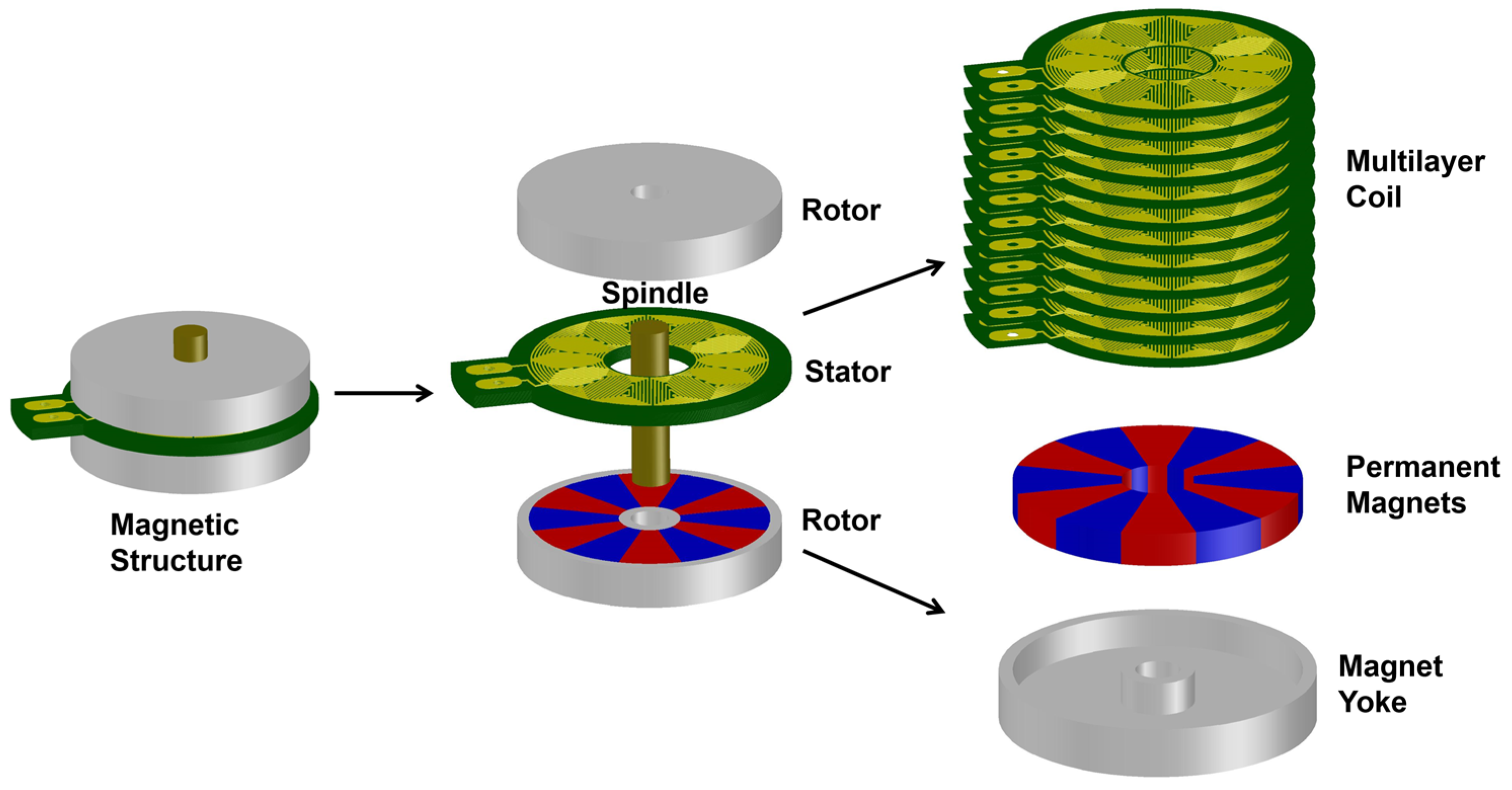
According to Faraday’s law, a voltage will be produced in the coil either by moving the magnet, while keeping the coil fixed or vice versa, and two generators are studied. Generator 1 is the coil-fixing generator and Generator 2 is the magnets-fixing generator.

2.1. Overall Design

In order to reduce the magnetic resistance torque, the two generators utilize static magnetic fields. Generator 1 establishes the static magnetic field by consisting of a multilayer planar coil as the stator and two multi-pole PM rotors on both sides of the coil. Generator 2 adopts the multilayer planar coil as the rotor and the multi-pole PMs as the stator, which can decrease the starting torque because of its lower rotor mass and moment of inertia and save more space by eliminating the casing.
Generator 1 consists of a magnetic structure, a casing and a turbine, as shown in Figure 1. The magnetic structure is the key structure that converts mechanical energy to electrical energy. The casing is used to protect and support the magnetic structure. The turbine harvests the mechanical energy from the environment to drive the rotating parts. Among the three main components, casing and turbine can be substituted or used for other purposes according to various requirements, while the magnetic structure is the critical part for energy conversion and thus we focus on study of the magnetic structure in this article. The magnetic structure is composed of a spindle, a multilayer planar coil (stator) and two multi-pole PM (rotors), as illustrated in Figure 2. p pairs of sector PMs are imbedded in a annular yoke to compose one rotor. The magnetic field direction of each PM is along the axial direction and every two neighboring PMs are placed in opposite directions. The multilayer coil is placed in the air gap and serves as a stator. To establish a static magnetic field, two rotors are fixed on both sides of the coil. While working, the static magnetic field reduces magnetic resistive torque, hysteresis loss, and eddy-current loss greatly, hence improving the generating performance significantly. In order to reduce the magnetic resistance torque and magnetic flux leakage as well as to improve the magnetic flux density in the air gap, yokes were adopted. To maximize the magnetic flux density and to fully exploit the in-plane space, magnets and microcoils are designed in sector-shape. Considered the simulation results and fabrication limitations, the design parameters and their values used in prototypes are decided after optimization and listed in Table 1. The design choices for the parameters are discussed in the following sections.
Figure 1. The coil-fixing generator prototype and the components.
Energies 08 11755 g001
Figure 2. The magnetic structure of the miniaturized planar magnetic generator.
Energies 08 11755 g002
Table 1. Design parameters and values in Generator 1 and Generator 2.
ParameterDescriptionValue in Generator 1Value in Generator 2
RciInner radius of sector coil2 mm2 mm
RcoOuter radius of sector coil5 mm5.1 mm
RmiInner radius of sector magnet1.3 mm1.6 mm
RmoOuter radius of sector magnet5.1 mm6.5 mm
hmMagnet thickness1.2 mm1.2 mm
heYoke thickness0.6 mm1.3 mm
hcMultilayer coil thickness 0.3 mm (6 layers) 0.6 mm (12 layers)0.3 mm (4 layers) 0.9 mm (12 layers)
hδAir-gap thickness1 mm1.2 mm
pNumber of pole pairs66
qLinewidth and spacing of microcoil75 μm 75 μm
θPole angle30°30°
Figure 3 compares Generator 1 and Generator 2. Like Generator 1, Generator 2 has PMs on both sides of the coil to establish a static magnetic field. The coil performs as the rotor instead of magnets. Hence the mass and inertia moment of the rotor are lower, leading to further decrease of the starting torque. To cut off the volume occupied by casing, magnets and yokes are fixed by a sleeve and a spacer, and the axial dimension is reduced greatly. Consequently, the dimensions of the generator decreased from 2.61 cm3 to 0.92 cm3. The parameters of Generator 2 are also listed in Table 1.
Figure 3. (a) Schematic of Generator 1, coil-fixing generator; (b) Schematic of Generator 2, magnets-fixing generator.
Energies 08 11755 g003

2.2. Magnetic Material Selection
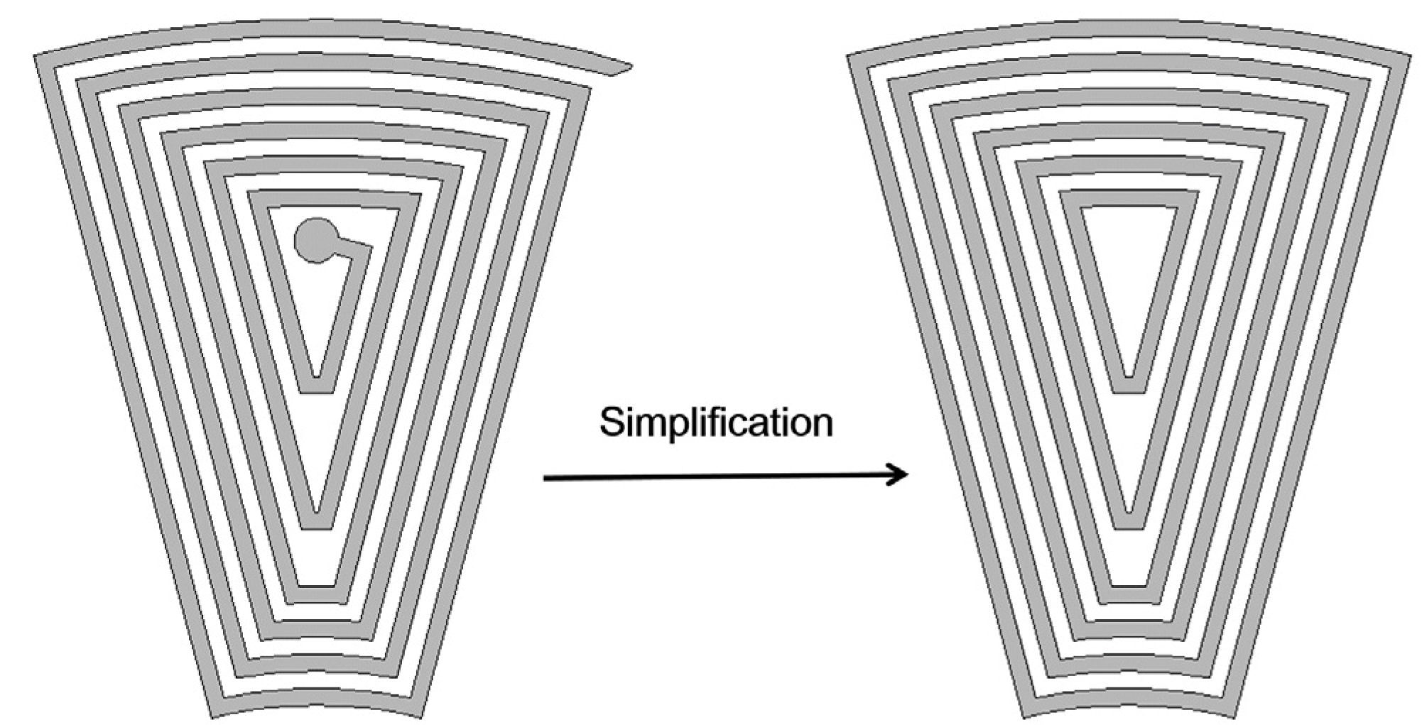
Magnetic materials used in the generators affect the magnetic field distribution directly, which also significantly impact the output performance. To achieve higher magnetic flux intensity, the material with a higher residual induction is preferred for PMs. Therefore, NdFeB N52 (neodymium iron boron) is selected, whose residual induction is 1.43 T and relative permeability is 1.05. Yokes are made of soft magnetic materials. In order to achieve a high saturation flux density to decrease yoke volume and a high magnetic permeability to decrease leakage flux, we chose permalloy 1J85, permalloy 1J50, electromagnetic pure iron and ferrocobalt 1J22 firstly. To determine the material for yokes, experiments were carried out in our previous work [15]. Consequently, heat-treated permalloy 1J50 presents the best performance, hence is chosen as yoke material.

2.3. Coil Design

Besides the magnets and yokes, coil is another vital part in the magnetic structure. In order to produce high output voltage, coils are designed in single-phase structure which is especially necessary when the rotation speed is low. Compared with three-phase and multi-phase coil, single-phase coil spares the rectifier circuits as well as simplifies the coil fabrication process.

2.3.1. Coil Design of Coil-Fixing Generator (Generator 1)

Stator coil is a multilayer planar coil consisting of several coil-units. Each coil-unit is composed of an upper layer and a lower layer and each layer has p pairs of sector-spiral microcoils as shown in Figure 4. In order to fully exploit the space and maximize the magnetic flux through each microcoil, the p pairs of sector-spiral microcoils of each layer are arranged in annular. The two microcoils of one pair are connected in series as presented in Figure 5a. In one coil-unit, each microcoil is connected by via hole at the center to the coil above or below it, as shown in Figure 5b, thus all the microcoils of a coil-unit are connected in series.
Figure 4. A coil-unit is composed of an upper layer and a lower layer.
Energies 08 11755 g004
Figure 5. (a) A pair of sector- spiral microcoils; (b) Magnetic flux through microcoils.
Energies 08 11755 g005
According to Faraday’s law of electromagnetic induction, the induced voltage of each layer can be expressed as Equation (1).
U ( t ) = 2 p d Φ c ( t ) d t = 2 p 2 Ω S c B c , max cos ( p Ω t )
where Φc is the magnetic flux through a sector-spiral microcoil, Sc is the area enclosed by a microcoil, Bc,max is the maximum magnetic flux density, Ω is the rotation speed (rad/s). Several coil-units are stacked to form a multilayer planar coil. To improve the output voltage, the coil-units are wired in series so that the generator can supply enough voltage even at a low rotation speed. The output voltage Us (at no load) can be written as below
U s ( t ) = i = 1 N U i ( t ) = 2 p 2 Ω S c B c , max cos ( p Ω t ) i = 1 N B c , max ( i )
where i denotes different layers. To calculate Sc, a sector-spiral microcoil is simplified to discontinuous enclosed sectors, as illustrated in Figure 6. The sum of the enclosed areas of all the enclosed sectors can approximate Sc. Apparently, Sc is roughly in the inverse proportional relationship to the number of pole pairs, p. Besides, the output voltage amplitude Us is proportional to p2 and Sc. Under these conditions, Equation (2) predicts Usp. Therefore, increasing p can improve the output voltage Us. While it sacrifices Sc and decreases the volume of each magnet. Enough space of Sc is necessary for the via holes and small magnets are difficult to fabricate, magnetize and assemble. A balance should be established among the parameters and the pole number of 6 is chosen considering the above factors.
Figure 6. A sector-spiral microcoil is simplified to several discontinuous enclosed sectors.
Energies 08 11755 g006

2.3.2. Coil Design of Magnets-Fixing Generator (Generator 2)

The rotor coil in Generator 2 shares similar structure with the stator coil in Generator 1 as a multilayer planar coil consisting of several coil-units and each coil-unit is composed of an upper layer and a lower layer. While in order to achieve the coil rotating idea, several efforts are performed. In Generator 1, both of the pads for conducting the positive pole and negative pole of the coil are placed on the same surface. While in order to conduct the electricity in the rotating coil, these two poles are placed on the upper surface and lower surface of the multilayer coil respectively, as shown in Figure 7. Furthermore, two conductive spindles are used to connect the upper-surface pad and the lower-surface pad respectively, and an insulative inner spindle is adopted to connect the two spindles, as shown in Figure 3b. Besides, two brushes are utilized to conduct the electric power from the conductive spindles to wires. The brush is made of an arc-shaped conductive wire manually without introducing much resistance. Grooves at the periphery of the coil are used to locate the coils of different layers while assembling.
Figure 7. Pads in Generator 2.
Energies 08 11755 g007

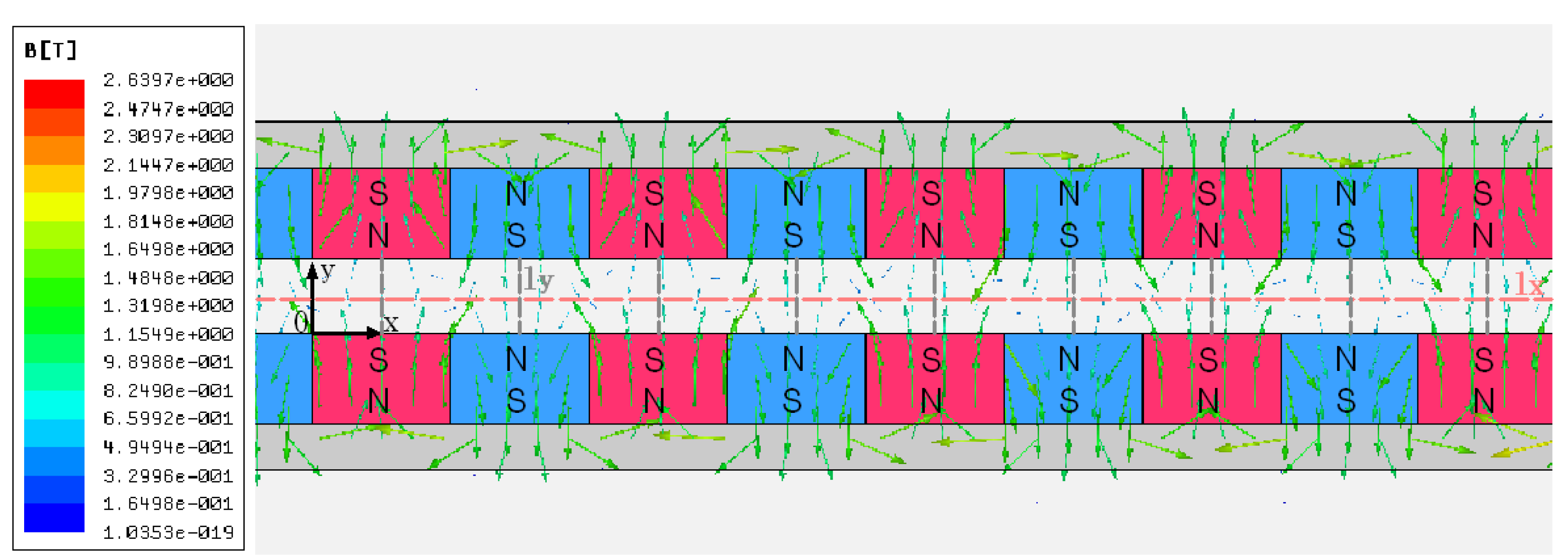
2.4. Magnetic Structure Design

In order to optimize the parameters of magnets, magnetic circuit analysis and FEA method are utilized to analyze the magnetic field distribution. Since Generator 1 and Generator 2 share the same analytical method, we take Generator 1 as an example to introduce the analysis. A circumferential cross section in the magnetic structure is expanded into a plane as a two-dimensional (2D) model shown in Figure 8a. The green line represents the main flux path. d is the width of a PM and defined as (Rco + Rci) π/2p in Figure 8b.
Figure 8. (a) The 2D model of the generator magnetic structure; (b) structural parameters of sector magnets.
Energies 08 11755 g008
According to Equation (2), it is obvious that the magnetic flux density through the stator coil is key for the induced voltage. The approximate expression of Bδ is given by Equation (3), as illustrated in our previous work [13]. Br is the PM residual induction, σ is the leakage coefficient with a value of 1.1~1.3 for planar generators.
B δ B r 2 h m 2 σ h m + h δ = B r 2 h m / h δ σ ( 2 h m / h δ ) + 1
Das et al. derives the air-gap magnetic flux density through magnetic vector analysis in reference [14], giving a similar result with Equation (3). It proves that the magnetic circuit analysis used here is reasonable. To keep yokes unsaturated, the minimum value of yoke thickness is determined when the yokes work on the knee point of the magnetization curve where the curve begins to bend, and the knee-point value Bx of 1J50 is 1 T. Based on the principle of uniform flux distribution, the magnetic flux in the yoke can be expressed as below.
Φ e = B e h e ( R m o R m i ) 1 2 B δ π ( R m o 2 R m i 2 ) 2 p
B e B X
where Φe is the yoke magnetic flux, Be is the yoke magnetic flux density. The yoke thickness he can be expressed by
h e π ( R m o + R m i ) B δ 4 p B X
To better study the distribution of magnetic field, FEA simulations are carried out by using Ansoft Maxwell software (ANSYS, Inc., Pittsburgh, PA, USA). For magnetic structures of different sizes, given the same magnetic material and the same shape ratios, the magnetic field distribution will be the same [16]. Figure 9 shows the 2D model of the magnets and yokes used in Ansoft calculations, and the structural parameters are listed in Table 1. Since the magnetic permeability of the stator coil is nearly the same as that of air, the coil is modeled as air. The magnetic flux distributions produced by 2D simulations are also shown in Figure 9. And the magnetic field is symmetric about the middle line lx of the air gap.
Figure 9. The magnetic flux distribution simulated by Ansoft.
Energies 08 11755 g009
The air-gap magnetic flux density vector Bδ can be decomposed into two components on the x-0-y plane: the x-component Bδx and the y-component Bδy. Bδy is perpendicular to the coil plane and effective for electricity generating. Figure 10 shows the periodic distributions of Bδy along the lines parallel to x-axis of different y-coordinates from 0 to 0.5 mm (0~he/2). The values of Bδy decrease and become more uneven when being away from the surface of PMs. The maximum Bδy locates at the middle line ly of each pair of PMs. The values of Bδy along the PM middle line ly are shown in Figure 11, and serve as the maximum coil magnetic flux density Bc,max in Equation (2).
Figure 10. The periodicity distributions of Bδy along the lines parallel to x-axis of different y-coordinates from 0 to 0.5 mm (0~he/2).
Energies 08 11755 g010
Figure 11. The values of Bδy along the permanent-magnet (PM) middle line ly.
Energies 08 11755 g011
The Bδy value of 0.7 T~0.85 T on the surface of PMs (y = 0 or 1 mm in Figure 10) roughly agrees with the value of 0.83 T evaluated by magnetic circuit analysis method (Equation (3), σ is assigned to 1.3). It indicates that magnetic circuit analysis can roughly describe the magnetic field distribution with little calculation cost, which is useful for the preliminary design of the magnetic planar micro generator.
Furthermore, the shape ratios of PM width and PM thickness to air-gap thickness are the key structural parameters significantly affecting the air-gap magnetic flux density. Optimized values of the two parameters are found in our previous research [13] based on the considerations of both the air-gap magnetic flux density and the magnetic structure volume. The reasonable range of PM thickness to air-gap thickness ratio k1 (k1 = 2hms/hδ) is 1.4 to 2 and PM width to air-gap thickness ratios k2 (k2 = d/hδ) is 1.25 to 2. The geometric parameters (radios and thickness) of the magnetic components adopted in this paper basically obey to these rules.

3. Fabrication

Considered the prospective output performance and volume limitation, we design and optimize the values of the parameters with the theoretical methods studied above, as listed in Table 1. Multilayer-coil is fabricated by Flexible Printed Circuits (FPC) technology and made of nonmagnetic materials, copper for the wires and flexible polymer materials for the substrate. Compared with MEMS process, FPC technology is inferior on decreasing the line width and the spacing of coils, while it can easily connect coils of different layers by via holes with a high reliability. Compared with the coils fabricated by traditional filament winding method, the FPC based multilayer coil integrates coils and substrates within an integrated thin structure, leading to a smaller air-gap thickness and higher air-gap magnetic flux density, hence better output performance. Other components of the generator prototype are fine machined.
In Generator 1, six-layer coils are fabricated with an internal resistance of 58 Ω and a thickness of 0.3 mm. Decreasing line width of coil may increase the area enclosed by each sector microcoil and improve output voltage, while it introduces internal resistance of coil and decrease output power. Based on the above considerations, line width and spacing of the wires are both designed as 75 μm. Two coils are wired in series, and the coil is 12 layers. The prototype volume with a casing was 2.61 cm3 and the magnetic structure was 0.38 cm3 as shown in Figure 12a. For the volume calculations, only the magnetic structure volume is considered, rather than the total generator volume. This is because the space can be used for other purposes if not taken by the magnetic structure in a highly integrated system [2]. The generator volume, including casing, could be reduced to less than 1 cm3 by replacing the bearings with micro balls and other ways to minimize unnecessary parts.
Figure 12. (a) The magnetic structure of the generator, and a six-layer coil and a PM rotor; (b) Magnets-fixing generator.
Energies 08 11755 g012
In Generator 2, the total height of the generator is reduced from 13 to 6.2 mm and the total volume of the generator is 0.92 cm3 and the magnetic structure is 0.823 cm3, as show in Figure 12b. The decrease of volume mostly attributes to the reduction of axial dimension. In order to reduce the internal resistance of the coil, the height of the copper within the coil is 35 μm instead of the 22 μm height copper adopted in the coil-fixing generator. A four-layer coil is designed and fabricated. Three four-layer coils are connected in series in Generator 2. Consequently, the internal resistance of a 12-layer coil decreased to 70.5 Ω.

4. Experiments and Results

Figure 13a shows the experimental apparatus for testing of the fabricated devices, consisting of an air compressor, an anemograph, a wind tunnel and an oscilloscope. The generator was fixed inside the wind tunnel and driven by wind power. There is a pitot tube of the anemograph placed near the turbine to measure the wind speed. The wind speed could be controlled by the air compressor. The oscilloscope was used to display the output voltage Us, which was a sine wave presented in Figure 13b. Us was also predicted by Equation (2).
In Generator 1, Sc was 11.2 mm2 and Bc,max in each coil layer was obtained from Figure 11 and i = 1 12 B c , max ( i ) = 8.271 T. The comparison between the theoretical predictions and experimental results are shown in Figure 14a. A good agreement is observed with errors less than 4%. Between the output voltage amplitude and the rotation speed, there is a linear factor of 0.686 V/(kr/min). The consistency between the experimental results and theoretical predictions indicates the calculation method proposed in this paper is reliable. The internal resistance of the generator was 116 Ω, and the generator was terminated with a matched resistor for max output power, which could reach 0.521 W at a rotation speed of 32 kr/min. In Generator 2, Sc was 11.9 mm2 and Bc,max in each coil layer was obtained and i = 1 12 B c , max ( i ) = 8.580 T. The results show that between the output voltage amplitude and the rotation speed, there is a theoretical linear factor of 0.771 V/(kr/min). Figure 14b compares the theoretical predictions and experimental results. (Experimental results of Generator 2 under high speed are not showed since under which the output performance is not steady because of the limitations of fabrication and assembly. Among which, the sleeve was made of polyformaldehyde that contributes to the unsteadiness.) The errors are less than 4% that verifies the reliability of the analysis again. Generator 2 featured an internal resistance of 70.5 Ω and the max output power was 0.0395 W at a rotational speed of 6.3 kr/min. Both of the generators could start working at a low wind speed of 1~2 m/s and there is no obvious difference between the wind speed under which they could start working. This is because it is unavailable to control the wind speed so accurately.
Figure 13. (a) Testing system for the generators; (b) The output voltage wave of a generator prototype.
Energies 08 11755 g013
Figure 14. (a) The theoretical values and experimental results of the output voltage amplitude; (b) the theoretical values and experimental results of the output voltage.
Energies 08 11755 g014

5. Discussion

The prototypes are compared with the generators studied in other references, as listed in Table 2. The most outstanding character of the generators discussed in this paper is the high normalized voltage. This profit results from the generator structure where magnets and yokes cannot move relative to each other. A static magnetic field is established so that the magnetic resistance torque, hysteresis loss, and eddy-current loss are decreased. In addition, generator 1 performs steady under a wide range of wind speed. Generator 2 saves more space by eliminating the casing structure, while it introduces more components such as the connected spindles and bushes that demands better fabrication and assembly accuracy. While the generator in reference [7] has the highest normalized voltage, its volume is the biggest and the outer radius of which is 12.5 mm. That means it occupies four times space of our generators in a plane. In addition, to achieve the high normalized voltage, it adopted a 20-layer coil that results in a big internal resistance, hence a low output power. Reference [9] presented an air-driven micro generator implemented by MEMS processing which is instructive for our future research. Considered all of the output performance, our generators are of high efficiency. This work successfully achieved the miniaturization of AFPM generator with static magnetic field. Further investigation will focus on decreasing the internal resistance of coils and volume of the generator using other technologies, such as MEMS process.
Table 2. Comparisons of magnetic planar micro generators.
ReferenceVolume (cm3)Rotation Speed (krpm)No-Load Vrms (V)Normalized Voltage (mV·krpm−1)Internal Resistance (Ω)Max. Power (Wrms)Power Density (W·cm−3)
Generator 10.383215.554851160.5211.37
Generator 20.8236.23.33753870.50.03950.048
[3]0.052.20.111504.1 × 10−48.2 × 10⁻³
[8]0.76113.30.21816.39
[4]3.4 × 10−33920.120.311.86.6 × 10−31.95
[5]0.112000.4642.320.321.059.5
[6]0.077109.26 × 10−30.9260.233.6 × 10−44.6 × 10⁻³
[7]1.25343.28005.8 × 10−34.63 × 10⁻³
[9]0.041300.4214450.00110.027
[10]0.0233804.18115.0220
[11]0.1461200.504.21.38.9
[12]0.1363051.605.24 8.059

6. Conclusions

In this paper, two miniaturized planar magnetic generators are developed to convert wind energy to electric energy, working as renewable energy sources for low-power devices. In order to decrease the resistance torque existed in miniaturized generators, we have studied Generator 1 with static magnetic field at working. Generator 2 adopts the multilayer planar coil as the rotor and the multi-pole PMs as the stator to further save more space without compromising the magnetic structure or output performance. These generators can harvest energy from wind. Additionally, output voltage can be estimated precisely by the theoretical model at better than 96% accuracy. The normalized voltages of Generator 1 and Generator 2 reach 485 mV/krpm and 538 mV/krpm respectively. Overall, the generators have advantages such as small size, high efficiency, low starting torque and a long lifetime. It can be used to produce electric energy in limited space where wind energy exists, for example, to provide electrical energy for wireless sensor node placed inside an air shaft, thus acting as an alternative to batteries.

Author Contributions

The paper was completed in collaboration among the three authors. Gengchen Shi proposed the research theme and idea. Jingjing Zhao and Lin Du completed the design, fabrication, and characterization of the generators. All authors have read and approved the final manuscript.

Conflicts of Interest

The authors declare no conflicts of interest.

References

  1. Tang, R.; Yuan, D. Modern Permanent Magnet Machines-Theory and Design; Machine Press: Beijing, China, 1997; Volume 4, pp. 329–330. [Google Scholar]
  2. Arnold, D.P. Review of microscale magnetic power generation. Magn. IEEE Trans. 2007, 43, 3940–3951. [Google Scholar] [CrossRef]
  3. Pan, C.T.; Wu, T.T. Development of a rotary electromagnetic microgenerator. J. Micromech. Microeng. 2007, 17, 120–128. [Google Scholar] [CrossRef]
  4. Herrault, F.; Ji, C.H.; Allen, M.G.; Toulouse, E.D. Ultraminiaturized High-Speed Permanent-Magnet Generators for Milliwatt-Level Power Generation. J. Microelectromech. Syst. 2008, 17, 1376–1387. [Google Scholar] [CrossRef]
  5. Herrault, F.; Yen, B.C.; Chang-Hyeon, J.; Spakovszky, Z.S.; Lang, J.H.; Allen, M.G. Fabrication and Performance of Silicon-Embedded Permanent-Magnet Microgenerators. J. Microelectromech. Syst. 2010, 19, 4–13. [Google Scholar] [CrossRef]
  6. Sun, S.C.; Shi, G.C. Design and fabrication of micro rotational generators. Opt. Precis. Eng. 2011, 6, 1306–1312. [Google Scholar]
  7. Cordero, R.; Rivera, A.; Neuman, M.; Warrington, R.; Romero, E. Micro-Rotational Electromagnetic Generator for High Speed Applications. In Proceedings of the 25th International Conference on Micro Electro Mechanical Systems (MEMS), Paris, France, 19 January–2 February 2012; pp. 1257–1260.
  8. Chen, Y.J.; Pan, C.T.; Liu, Z.H. Analysis of an in-plane micro-generator with various microcoil shapes. Microsyst. Technol. 2013, 19, 43–52. [Google Scholar] [CrossRef]
  9. Holmes, A.S.; Hong, G.; Pullen, K.R. Axial-flux permanent magnet machines for micropower generation. Microelectromech. Syst. J. 2005, 14, 54–62. [Google Scholar] [CrossRef]
  10. Raisigel, H.; Cugat, O.; Delamare, J. Permanent magnet planar micro-generators. Sens. Actuators A Phys. 2006, 130–131, 438–444. [Google Scholar] [CrossRef]
  11. Arnold, D.P.; Das, S.; Park, J.W.; Lulica, Z.; Jeffrey, H.L.; Allen, M.G. Microfabricated high-speed axial-flux multiwatt permanent-magnet generators-part II: Design, fabrication, and testing. J. Microelectromech. Syst. 2006, 15, 1351–1363. [Google Scholar] [CrossRef]
  12. Arnold, D.P.; Herrault, F.; Zana, I.; Galle, P.; Park, J.; Das, S.; Lang, J.H.; Allen, M.G. Design optimization of an 8-Watt, microscale, axial-flux, permanent-magnet generator. J. Micromech. Microeng. 2006, 16, 290–296. [Google Scholar] [CrossRef]
  13. Gieras, J.F.; Wang, R.J.; Kamper, M.J. Axial Flux Permanent Magnet Brushless Machines; Springer: New York, NY, USA, 2008; Volume 1, p. 7. [Google Scholar]
  14. Howey, D.A.; Bansal, A.; Holmes, A.S. Design and performance of a centimetre-scale shrouded wind turbine for energy harvesting. Smart Mater. Struct. 2011, 20, 085021. [Google Scholar] [CrossRef]
  15. Zhao, J.; Shi, G.; Du, L. Design method of magnetic circuit in planar permanent magnetic micro-generator. Acta Armamentarii 2014, 35, 1144–1151. [Google Scholar]
  16. Das, S.; Arnold, D.P.; Zana, I.; Jin-Woo, P.; Allen, M.G.; Lang, J.H. Microfabricated high-speed axial-flux multiwatt permanent-magnet generators—Part I: Modeling. J. Microelectromech. Syst. 2006, 15, 1330–1350. [Google Scholar] [CrossRef]

