
The Three-Phase Power Router and Its Operation with Matrix Converter toward Smart-Grid Applications

Abstract
: A power router has been recently developed for both AC and DC applications that has the potential for smart-grid applications. This study focuses on three-phase power switching through the development of an experimental setup which consists of a three-phase direct AC/AC matrix converter with a power router attached to its output. Various experimental switching scenarios with the loads connected to different input sources were investigated. The crescent introduction of decentralized power generators throughout the power-grid obligates us to take measurements for a better distribution and management of the power. Power routers and matrix converters have great potential to succeed this goal with the help of power electronics devices. In this paper, a novel experimental three-phase power switching was achieved and the advantages of this operation are presented, such as on-demand and constant power supply at the desired loads.1. Introduction
Distribution power-grids are undoubtedly one of the most complex systems humanity has ever created. Their structural vulnerability is a crucial factor [1] and the introduction of smart-grids and renewable energy sources has increased the difficulty of the analysis [2] since many parameters have to be taken into consideration in contrast with the straight-forward classic power supply. This increase in complexity requires new methods of power routing. In other words, it is obvious that power management is necessary in order to perform an effective power routing of this vast amount of newly incorporated renewable resources.
The initial stage of a power router has already been developed for DC applications [3] where the power is transferred on demand from the desired source to the desired load. This is now expanded to include AC applications [4,5] with circuit switching of two power lines and multiple routers in both parallel and series configurations, i.e., an AC power routing network system can be created. The purpose of this project is to create a power network that can be readily adapted to the existing one, and can ultimately provide better regulation, distribution, and transmission of power. Power packet dispatching systems [6] and intelligent power switches [7,8] have also been investigated for the purpose of improved power delivery. The feasibility of the power router requires further testing for practical applications; however, this study is aimed at demonstrating the feasibility of power router switching in three-phase systems. Such a system is investigated in this work because three-phase systems are commonly used in the majority of power-grids.
Another emerging technology for power systems is the matrix converter [9], which also has potential in applications with renewable resources and smart-grids [10–12] as it can convert energy like a classic transformer but also offers other advantages such as control of bidirectional power flow and better isolation [13,14]. Previous studies have already experimented with a matrix converter [15] and AC conversion [16], and the combination of both in a single apparatus is a natural extension of this research.
Matrix converters have the potential to be an essential part of the power electronic transformer (PET) [17,18] as a crucial means of coordinating between centralized and decentralized control, as also one of the “great challenges” of the power systems mentioned in [19]. The conventional way of transformer reaches the end of its era with the constant development of power electronics and the introduction of matrix converter and PET. Matrix converter has shown good efficiency results with the use of SiC devices in higher switching frequencies [15], fact that allows the replacement of the classic transformer by matrix converter topologies. Furthermore, a matrix converter with high frequency transformers has already shown its superiority versus the conventional ways as in [20,21]. PET has the possibility of achieving this challenge since it implements power electronics devices that can easily function under control. Other great advantages of PET include reduction of the overall size and cost [22] by implementing high frequency operation. It is important to mention, that in the final PET design other issues have to be taken into consideration such as voltage insulation, core size, flux densities, etc. [23].
This paper consists of four sections including this introduction. Section II of this paper describes the power router and matrix converter, and how the overall circuit is assembled. Section III describes the experimental and simulated results for various switching scenarios. The final section presents our conclusions.
2. Matrix Converter and Power Router
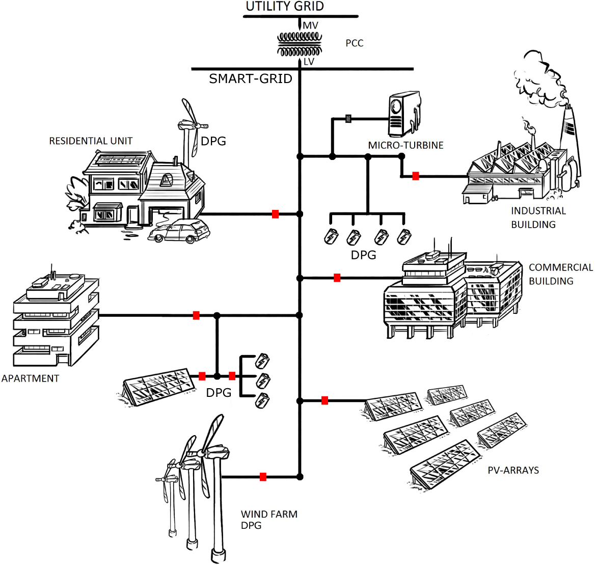
With the power control being increasingly decentralized, we consider the case of an area where power routers can be installed in every house or commercial facility, as shown in Figure 1. The utility-grid is linked to the smart-grid through the point of common coupling (PCC) with various loads and decentralized power generators (DPG) distributed throughout the latter smart-grid. The introduction of power routers, represented by the red blocks, enables the partitioning of the smart-grid into smaller segments, called micro-grids.
The PCC is conventionally a bulk transformer that can transform the medium level voltage supply to low voltage supply. The introduction of PET [24,25] however leads to better regulation and control of the bidirectional power flow between the utility- and smart-grids. A possible PET assembly compromises two AC/AC matrix converters with a high frequency link wherein a compact electronic transformer is installed. Various PET topologies have been compared in previous literature [26] and the efficiency superiority of high frequency transformer versus the conventional low frequency one is investigated in [27].
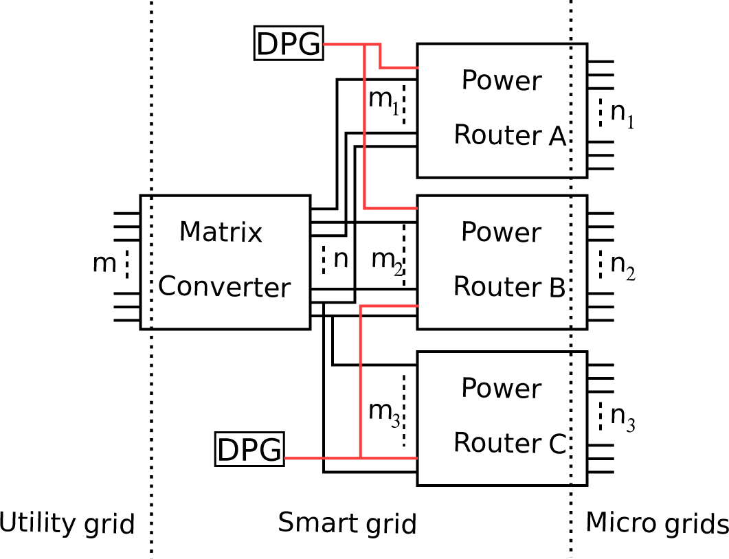
Power routers, which can be distributed according to the load-demand, can perform switching to connect particular loads with the desired input sources. We assume the routers and matrix converters to have m inputs and n outputs, as shown in Figure 2. The matrix converter receives the input phases from the utility-grid and outputs them to the power routers installed on the smart-grid which may also receive power from DPGs. One or more routers together can form a micro-grid according to the localized control system needs. This study considers the most common case scenario of a three-phase system. Therefore, we will scale down our experiments to only three-phases. It can be understood from Figure 2 that the power routers can form a power network that will be consisted not only from power utilities but also from information ones. This can also be described as a next step towards the so-called Enernet [28,29], where the electrical power (i.e., electrical energy) can coexist with the information (i.e., internet, communications, etc.) [30]. Another important part is to distinguish the roles of matrix converter and power router. Matrix converters have the ability to replace the bulk transformers by offering active control of the point of common coupling. That is the main reason a matrix converter is used in this experimental work. On the other hand, the main focus is on power line switching with the aid of power routers.
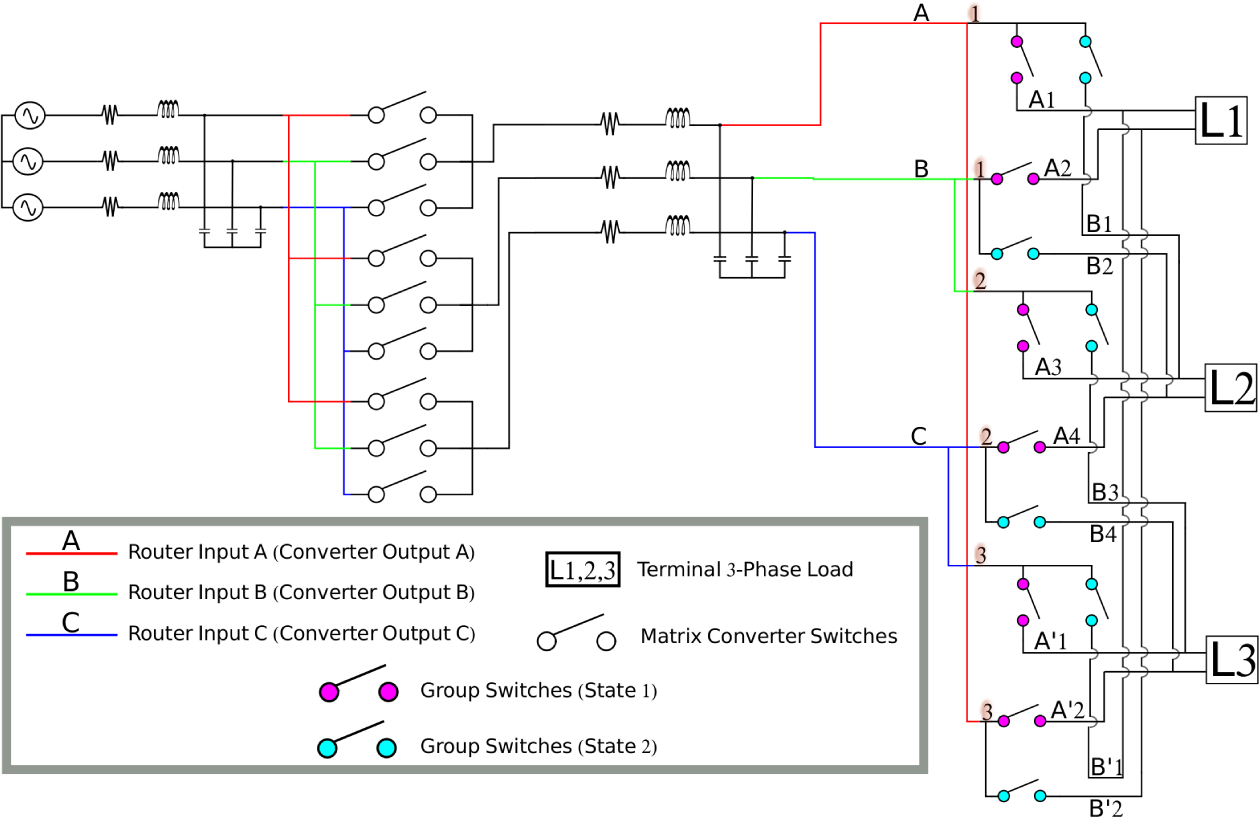
The matrix converter has already been studied through both simulation and experiment from the authors [15]. This is called direct topology and its main difference from the indirect one is the lack of the DC link. Several advantages of the DC link have been proposed for better power quality such as in [31]. On the other hand, the authors’ goal is mainly focused on a solid-state solution with no DC link for more compact final design. The behavior of the combined power router and matrix converter represents the next step towards the implementation of a system of PET with power routers. The system into consideration is shown in Figure 3. A three-phase voltage source feeds nine bidirectional switches with power supplied through the input filter. Ideal switches can be considered for the simulations but in the experiment two power MOSFETs with their sources connected can form a bidirectional switch. After the output filter, the lines are distributed to the inputs of the power router. It is important to note that a power router has several inputs. Apart from the three-phase utility-grid sources, renewable energy power sources could also be connected with the power router. This is exactly where the advantage and the full potential of the power router lie on. It can accordingly distribute the supplies to the equivalent loads by ensuring constant power at certain loads. In addition, it can use DPGs to their maximum capacity by ensuring a not overloaded utility-grid as well as a novel and agile power delivery.
The matrix converter utilizes the Venturini control modulation [32] described in [33]. This modulation creates an output voltage via the feedback of the input and target output voltages. As it was mentioned in the beginning, PET usually performs medium level voltage transformation into low level voltage (e.g., 6.6 kV to 100 V). In this paper, since the limitation of facilities at high voltage in laboratory, test level voltages are applied. As a result for the sake of equivalency in the experimental setup, the input voltage is set to 10 V and the voltage ratio of the matrix converter is set to 0.1 so that the output voltage of the converter is 1 V. Keeping the generality of discussion, let us consider the system base for both experiment and simulation results represented in per unit quantities. The LC filters are included in order to cut off any high frequency harmonics and are set as follows: L = 33 mH, C = 180 μF, Load1,2,3 = 15 Ω with the line resistances of a few Ohms for the sake of device protection. The switching frequency is set to 24.4 kHz and the pulses are digitally created utilizing a field programmable gate array (FPGA).
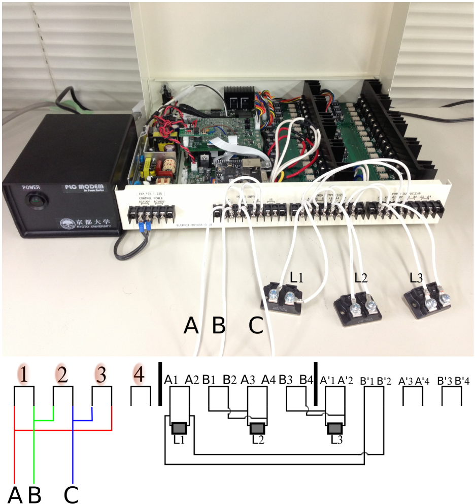
As it was mentioned before, smart power distribution, circuit switching, and constant power delivery to the desired loads are very challenging and important tasks. Ideally, all loads should have the capability of being fed with power from more than one input source. This basic switching scenario is also shown in Figure 3. The switches of the power router are separated into two groups. At first, the purple switches are on, and state 1 is set to the output. State 2 is set according to Table 1 during which the blue switches are on after the moment of switching. The loads are always fed with power but from different sources after the switching. The experimental prototype power router is shown in Figure 4. The line connections of the power cables are also schematically presented. Power router has four inputs and eight outputs and each input can be programmed to be outputted at one of its equivalent two outputs. Power line communication (PLC), which is the black box in the photograph, is used for controlling the power router through a personal computer. As Figure 4 shows, a power router input is considered to be a matrix converter output phase-to-phase voltage. When switching is performed such that a line is considered to fail, the equivalent phase-to-phase voltage is not reproduced at the output of the power router.
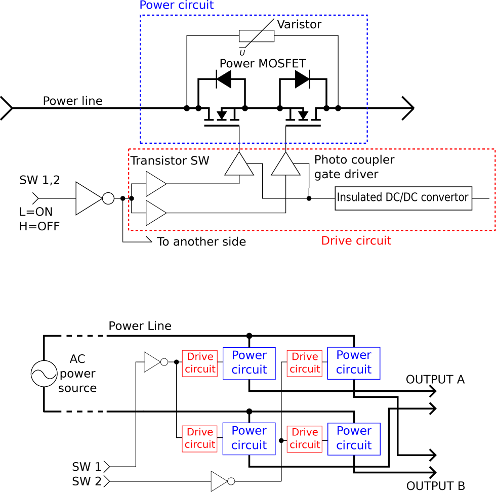
The power router specifications are a maximum operating voltage of 100–200 Vrms, continuous maximum power of 1 kW, and with Si-MOSFETs implemented as switches (450 V, 17 A). Increase of maximum power can be succeeded by implementing wide-bandgap SiC devices and such power routers are under development by our research group. Every ideal switch has to be implemented with the combination of two power MOSFETs. An insight figure of the power router is shown at Figure 5. How a single input phase can be transmitted to either of the two possible outputs is shown in the low part of the figure. Four bidirectional switches with their equivalent drive circuits are the main parts of the system. On the top, one of the bidirectional switches with its control circuit is graphically represented. It is obvious that the two MOSFETs have their sources connected so that only one drive circuit is sufficient. A photocoupler is the main responsible circuit for the bidirectional switch control. The combination of output ports among the different switch circuit units realises the circuit switching function of the power router. The design of the power router has scalability since the change of the number of switching circuit units does not affect the generality of the function. The following experimental results, although performed in test level voltages, can be scaled to higher voltage setup when the device ratings and power capacities are increased.
Although the isolation can be achieved in the PET topology, it can also be achieved in the topology of Figure 3 and especially of that of Figure 2. This ability is based on the power routers. The input of the system, i.e., the matrix converter, can be isolated in case of an emergency if the equivalent power router disconnects from its loads. As a result, the operation of the input and the other power routers can remain safe.
3. Results and Discussion
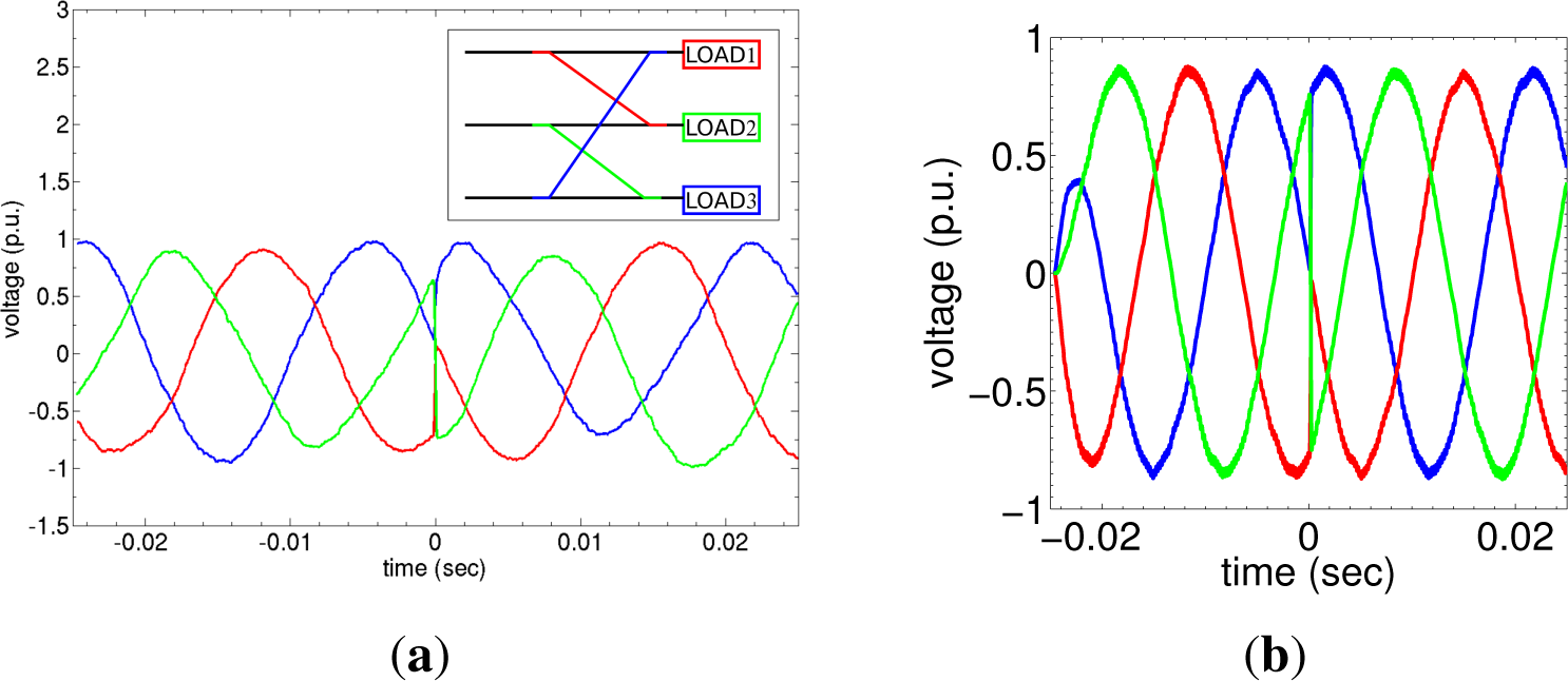
In the beginning, the scenario discussed in the previous section will be presented. It is a three-phase switching during which all the loads are connected to different inputs. In particular, Table 1 shows load 1 which is initially connected to phase AB, but after switching it is connected to phase CA. Load 2 switches from BC to AB, and load three switches from CA to BC. The experimental results are shown in Figure 6a. In the small circuit diagram, the colored lines indicate the line connections after switching and refer to the phase-to-phase voltages. The experimental result is also confirmed from the simulations in Figure 6b. If the practical system is considered (medium level voltage at 6.6 kV and low level voltage at 100 V) then 1 p.u. corresponds to 100 V. The simulations are generated from a Simulink Matlab model based on Figure 3.
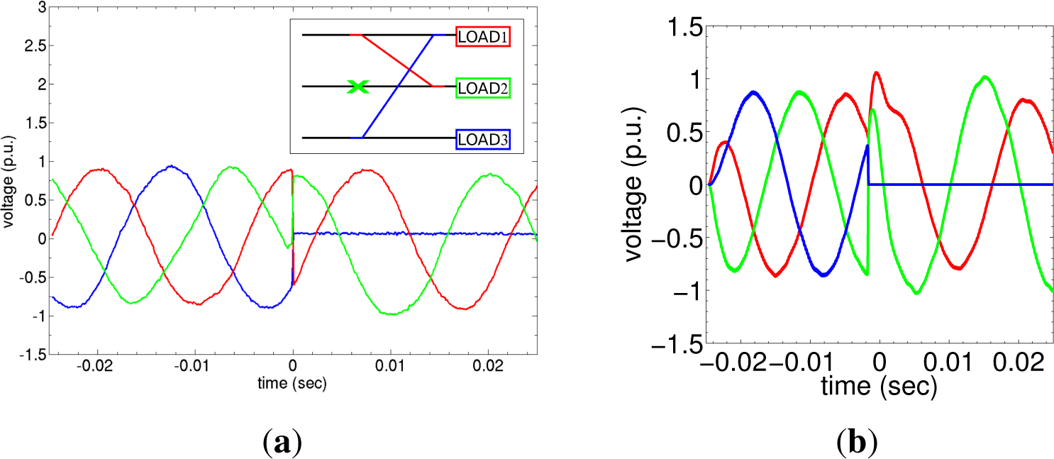
Various switching scenarios were further tested. Instead of a phase-to-phase voltage from now on, we will just refer to phase A, B, and C for the sake of simplicity. For the case of a critical load in phase C (load 3), phases B and C are disconnected from the output representative of a system failure. In this case, switching between phases A and C should take place as shown in Figure 7a. The voltage has been maintained at output C as a result of the succesful power routing. Verification of the experiment is shown in the simulation of Figure 7b. There is a small overvoltage in the output of power router after the moment of switching, which is possibly due to a resonance between the power router and the output filter of the matrix converter. On the other hand, some line resistances have been installed in the experimental power router input for its protection and also for the suppression of such kind of undesired transients.
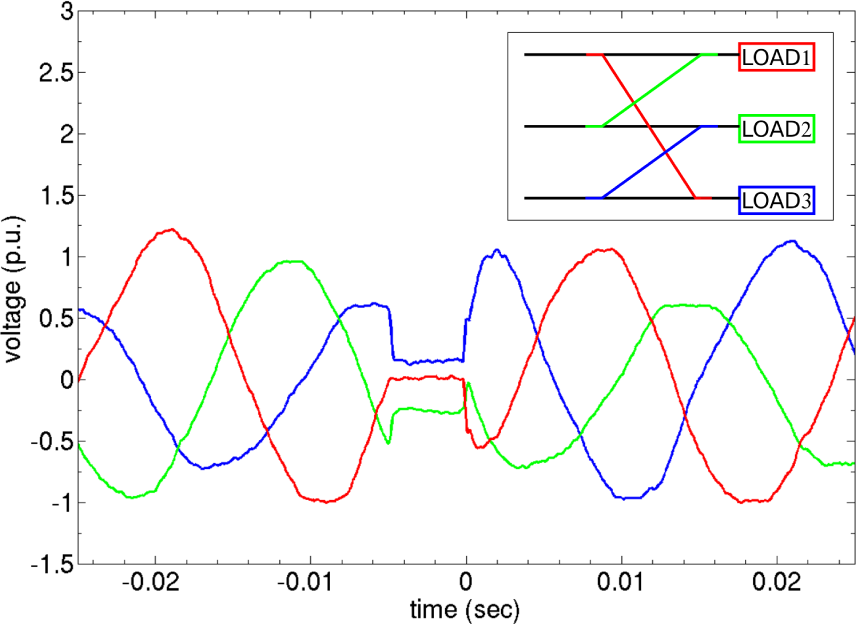
The final switching scenario is as shown in Figure 8a. In this case, phase B fails but load 2 is successfully fed with power due to switching with phase A. Phase C on the other hand feeds load 1 in phase A after power switching. In this case, load 3 has no power but the other two loads are successfully functioning. The transients are more obvious here, as shown in Figure 8b simulation results. Currents show similar behavior since we are experimenting with resistive loads.
In general, power router realizes the switching between two input lines at the moment when the two powers of these lines are equal in order to achieve soft-switching and reduce the power losses. During the above experiments however, several switchings are simultaneously performed so that hard-switching was also implemented. The Simulink model implements hard-switching techniques in all cases.
Future studies should include the investigation of new control methods with faster and lower power loss switching, as well as power routing with both DC and AC sources. Investigation of unbalanced input sources is also of great importance as the majority of loads throughout the grid are unbalanced. The matrix converter creates an unbalanced output supply and power routing is performed as shown in Figure 9. There is also a characteristic delay between the switching due to the fact that the power router is unable to function properly for some msec due to the voltage imbalance (i.e., power imbalance), but in the end it performs the necessary switchings. As it was mentioned before, power comparison decides the moment of switching. The unbalanced scenario creates unbalanced powers so as a result the comparison between them is a more complicated task for the control unit which is based on a more symmetrical scenario. We are currently working on such topics such as this delay reduction in order to reduce the switching losses. Load imbalance scenarios for power router are also investigated in [5]. In addition, the control modulation should cooperate with the power router so that matrix converter can create the desired voltage amplitude and phase correction according to the power need of each load. The main next topic is the inclusion of a PET in this system and the investigation of dynamics of the overall system. In detail, research remains to be done as far as the practical materials and engineering problems of PET are concerned including isolation, devices, and so on. These are the future problems as the history of conventional power apparatuses.
4. Conclusions
This paper demonstrates a novel three-phase power routing. An experimental prototype power router was used with a direct AC/AC matrix converter. The overall system was tested under various switching scenarios and was successfully operated. Matrix converters and power routers will constitute the next generation of power-grids so that their investigation in a unified system is critical. The overall system successfully performed power routing but with some delay in the unbalanced sources scenario.
Acknowledgments
This work is partially supported by the Regional Innovation Cluster Program “Kyoto Environmental Nanotechnology Cluster”, JST supported Super Cluster Project of Kyoto, Consultation of a High-Efficiency Energy Utilization System Realizing Clean and Low Environmental Load Society, and the Excellent Graduate Schools Program in Kyoto University. Moreover this work was supported by Global Warming Mitigation Measure Technology and Demonstration Research Project: “Developing a Local-Exchange Energy System that Uses the Rail System to Create Heat and Power Source Independency for Existing Equipment” by the Japanese Ministry of Environment (fiscal years 2012–2014). The authors are grateful to the reviewers for their comments and careful reading of the manuscript.
We would also like to acknowledge the assistance of ROHM Semiconductor Co. Ltd. for the prototype Silicon Carbide semiconductor providing. Alexandros Kordonis would also like to appreciate the help of Alexander Draude for his contribution of Figure 1.
Author Contributions
Alexandros Kordonis contributed to the simulation/experimental results and to the general organization of the article writing process. Ryo Takahashi and Daichi Nishihara contributed to the development of the power router and have the responsibilities on the programed operation. Takashi Hikihara has a responsibility on the project to develop PET and power router, including circuit design, based on the applications of SiC power devices. All of the authors contributed to the writing process of this research article.
Conflicts of Interest
The authors declare no conflict of interest.
References
- Mei, S.; Cao, M.; Zhang, X. Power Grid Complexity; Springer: Berlin, Germany, 2011. [Google Scholar]
- Hammons, T. Integrating renewable energy sources into european grids. Int. J. Electr. Power Energy Syst. 2008, 30, 462–475. [Google Scholar]
- Takuno, T.; Koyama, M.; Hikihara, T. In-home power distribution systems by circuit switching and power packet dispatching, Proceedings of the First IEEE International Conference Smart Grid Communications (SmartGridComm), Gaithersburg, MD, USA, 4–6 October 2010; pp. 427–430.
- Takuno, T.; Kitamori, Y.; Takahashi, R.; Hikihara, T. Ac power routing system in home based on demand and supply utilizing distributed power sources. Energies 2011, 4, 717–726. [Google Scholar]
- Takahashi, R.; Kitamori, Y.; Hikihara, T. Ac power local network with multiple power routers. Energies 2013, 6, 6293–6303. [Google Scholar]
- Tashiro, K.; Takahashi, R.; Hikihara, T. Feasibility of power packet dispatching at in-home dc distribution network, Proceedings of the IEEE Third International Conference Smart Grid Communications (SmartGridComm), Tainan, Taiwan, 5–8 November 2012; pp. 401–405.
- He, M.M.; Reutzel, E.M.; Jiang, X.; Katz, R.H.; Sanders, S.R.; Culler, D.E.; Lutz, K. An architecture for local energy generation, distribution, and sharing, Proceedings of the IEEE Conference Energy 2030, Atlanta, GA, USA, 17–18 November 2008; pp. 1–6.
- Lu, G.; De, D.; Song, W.Z. Smartgridlab: A laboratory-based smart grid testbed, Proceedings of the First IEEE International Conference Smart Grid Communications (SmartGridComm), Gaithersburg, MD, USA, 4–6 October 2010; pp. 143–148.
- Szczesniak, P. Three-Phase AC–AC Power Converters Based on Matrix Converter Topology; Springer: London, UK, 2013. [Google Scholar]
- Chang, Y.H. Design and analysis of power-cmos-gate-based switched-capacitor dc-dc converter with step-down and step-up modes. Int. J. Circuit Theory Appl. 2003, 31, 483–511. [Google Scholar]
- Sumithira, T.; Kumar, A.N. An experimental investigation on off-grid solar photovoltaic power system using matrix converter. J. Sci. Ind. Res. 2014, 73, 124–128. [Google Scholar]
- Cárdenas, R.; Peña, R.; Tobar, G.; Clare, J.; Wheeler, P.; Asher, G. Stability analysis of a wind energy conversion system based on a doubly fed induction generator fed by a matrix converter. IEEE Trans. Ind. Electr. 2009, 56, 4194–4206. [Google Scholar]
- Shah, J.; Gupta, R.K.; Mohapatra, K.K.; Mohan, N. Power management with a dynamic power limit by a power electronic transformer for micro-grid, Proceedings of the Power and Energy Society General Meeting, Minneapolis, MN, USA, 25–29 July 2010; pp. 1–5.
- Mohapatra, K.K.; Gupta, R.; Thuta, S.; Somani, A.; Umarikar, A.; Basu, K.; Mohan, N. New research on ac–ac converters without intermediate storage and their applications in power-electronic transformers and ac drives. IEEJ Trans. Electr. Electron. Eng. 2009, 4, 591–601. [Google Scholar]
- Kordonis, A.; Hikihara, T. Dynamic model of direct matrix converter and its experimental validation. Int. J. Circuit Theory Appl. 2015. [Google Scholar] [CrossRef]
- Kordonis, A.; Takahashi, R.; Hikihara, T. Ac/Ac converter towards power routing systems in smart-grids: Advantage on operation by nonlinear dynamics, Proceedings of the IEEE 2nd Global Conference Consumer Electronics (GCCE), Tolyo, Japan, 1–4 October 2013; pp. 158–159.
- Manjrekar, M.D.; Kieferndorf, R.; Venkataramanan, G. Power electronic transformers for utility applications, Proceedings of the Industry Applications Conference, Rome, Italy, 8–12 October 2000; 4, pp. 2496–2502.
- Ronan, E.R.; Sudhoff, S.D.; Glover, S.F.; Galloway, D.L. A power electronic-based distribution transformer. IEEE Trans. Power Deliv. 2002, 17, 537–543. [Google Scholar]
- Amin, S.M.; Wollenberg, B.F. Toward a smart grid: Power delivery for the 21st Century. IEEE Power Energy Mag 2005, 3, 34–41. [Google Scholar]
- Garces, A.; Molinas, M. A study of efficiency in a reduced matrix converter for offshore wind farms. IEEE Trans. Ind. Electron. 2012, 59, 184–193. [Google Scholar]
- Mohapatra, K.K.; Mohan, N. Matrix converter fed open-ended power electronic transformer for power system application, Proceedings of the Power and Energy Society General Meeting—Conversion and Delivery of Electrical Energy in the 21st Century, Pittsburgh, PA, USA, 20–24 July 2008; pp. 1–6.
- Shah, J.K. Dynamic Power Flow Control for a Smart Micro-grid by a Power Electronic Transformer. Ph.D. Thesis, University of Minnesota, Minneapolis, MN, USA, 2011. [Google Scholar]
- Erickson, R.W.; Dragan, M. Fundamentals of Power Electronics; Springer: New York, NY, USA, 2011. [Google Scholar]
- Iman-Eini, H.; Schanen, J.; Farhangi, S.; Barbaroux, J.; Keradec, J. A power electronic based transformer for feeding sensitive loads, Proceedings of the Power Electronics Specialists Conference, PESC 2008 IEEE, Rhodes, Greece, 15–19 June 2008; pp. 2549–2555.
- Basu, K.; Gupta, R.K.; Nath, S.; Castelino, G.F.; Mohapatra, K.K.; Mohan, N. Research in matrix-converter based three-phase power-electronic transformers, Proceedings of the IEEE International Conference Power Electronics Conference (IPEC), Sapporo, Japan, 21–24 June 2010; pp. 2799–2803.
- Sabahi, M.; Goharrizi, A.Y.; Hosseini, S.H.; Sharifian, M.B.B.; Gharehpetian, G.B. Flexible power electronic transformer. IEEE Trans. Power Electron. 2010, 25, 2159–2169. [Google Scholar]
- Kang, M.; Enjeti, P.N.; Pitel, I.J. Analysis and design of electronic transformers for electric power distribution system. IEEE Trans. Power Electron. 1999, 14, 1133–1141. [Google Scholar]
- Metcalfe, B. Presented at Singularity University, Moffett Field, CA, USA, July 2009.
- Patterson, B.T. DC, come home: DC microgrids and the birth of the “Enernet”. IEEE Power Energy Mag 2012, 10, 60–69. [Google Scholar]
- Ricciardi, S.; Santos-Boada, G.; Klinkowski, M.; Careglio, D.; Palmieri, F. Towards Service Orchestration between Smart Grids and Telecom Networks; Springer: Berlin, Germany, 2013. [Google Scholar]
- Watson, A.J.; Dang, H.Q.S.; Wheeler, P.W.; Clare, J.C.; Mondal, G.; Rufer, A.R.; Kenzelmann, S.; De Novaes, Y. A novel multilevel converter structure integrated into power systems and its performance evaluation, Proceedings of the 13th European Conference on Power Electronics and Applications, Barcelona, Spain, 8–10 September 2009; pp. 1–10.
- Venturini, M.; Alesina, A. The generalised transformer-a new bidirectional sinusoidal waveform frequency converter with continuously adjustable input power factor, Proceedings of the PESC’80, Power Electronics Specialists Conference, Atlanta, GA, USA, 16–20 June 1980; pp. 242–252.
- Wheeler, P.W.; Rodriguez, J.; Clare, J.C.; Empringham, L.; Weinstein, A. Matrix converters: A technology review. IEEE Trans. Ind. Electron. 2002, 49, 276–288. [Google Scholar]


| Load No. | State 1 | State 2 |
|---|---|---|
| 1 | AB | CA |
| 2 | BC | AB |
| 3 | CA | BC |
© 2015 by the authors; licensee MDPI, Basel, Switzerland This article is an open access article distributed under the terms and conditions of the Creative Commons Attribution license (http://creativecommons.org/licenses/by/4.0/).
Share and Cite
Kordonis, A.; Takahashi, R.; Nishihara, D.; Hikihara, T. The Three-Phase Power Router and Its Operation with Matrix Converter toward Smart-Grid Applications. Energies 2015, 8, 3034-3046. https://doi.org/10.3390/en8043034
Kordonis A, Takahashi R, Nishihara D, Hikihara T. The Three-Phase Power Router and Its Operation with Matrix Converter toward Smart-Grid Applications. Energies. 2015; 8(4):3034-3046. https://doi.org/10.3390/en8043034
Chicago/Turabian StyleKordonis, Alexandros, Ryo Takahashi, Daichi Nishihara, and Takashi Hikihara. 2015. "The Three-Phase Power Router and Its Operation with Matrix Converter toward Smart-Grid Applications" Energies 8, no. 4: 3034-3046. https://doi.org/10.3390/en8043034