
Improved Adaptive Droop Control Design for Optimal Power Sharing in VSC-MTDC Integrating Wind Farms

Abstract
:1. Introduction

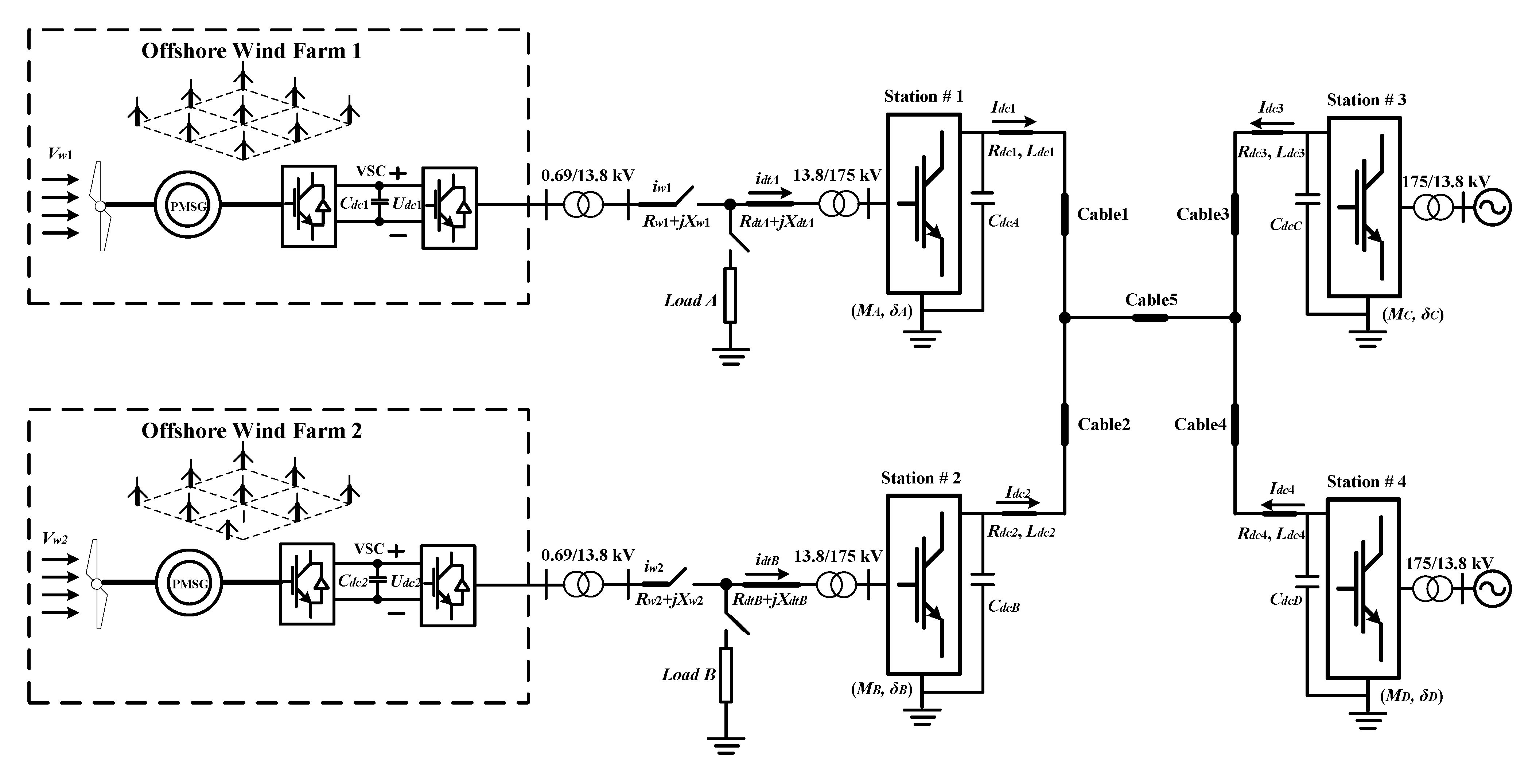
2. Modeling and Control of MTDC
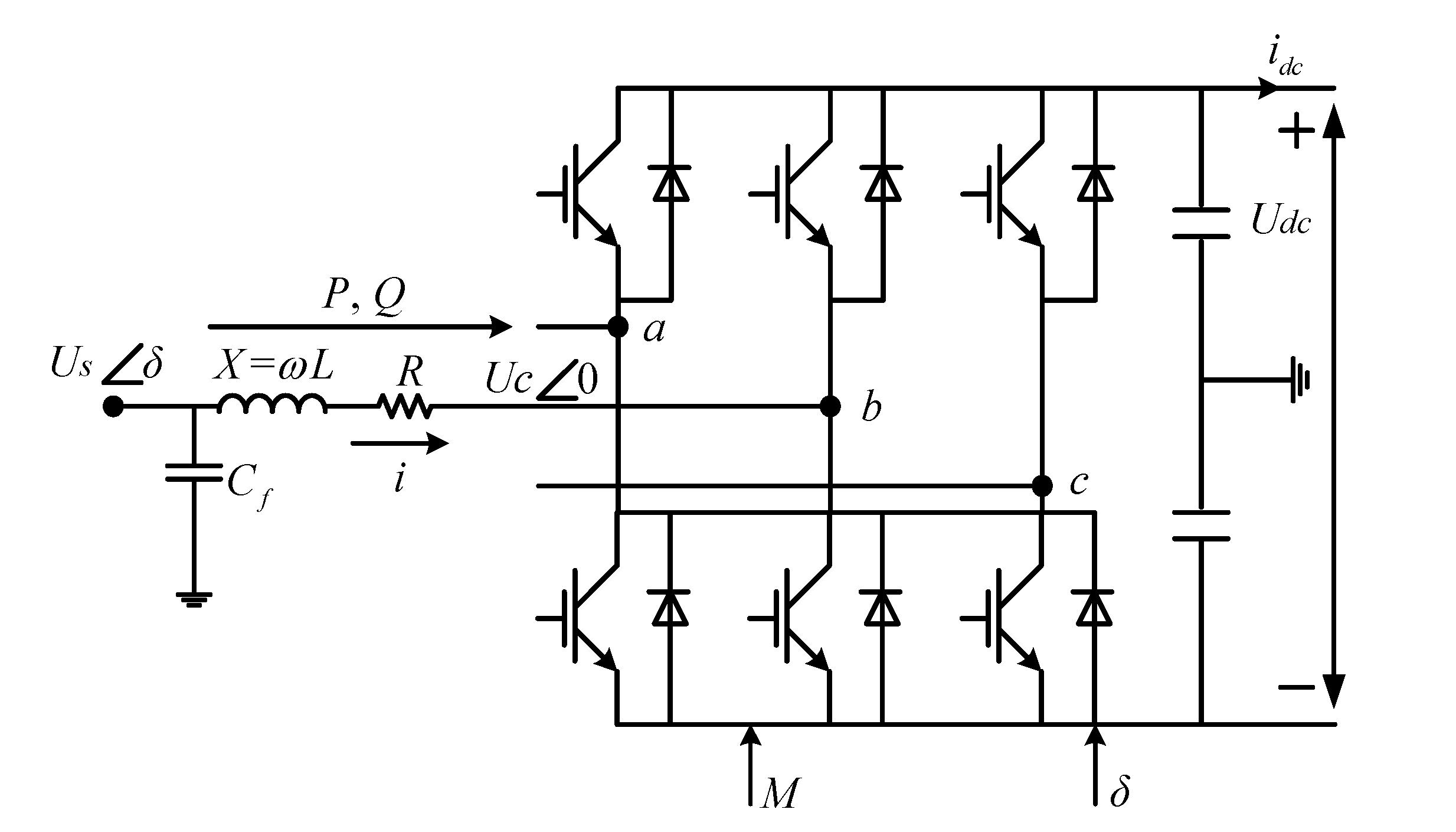
2.1. Converter Modeling

- (i)
- Angle of phase shifting:
- (ii)
- Modulation index:
2.2. Control Method of VSC-MTDC Integrating Wind Farm

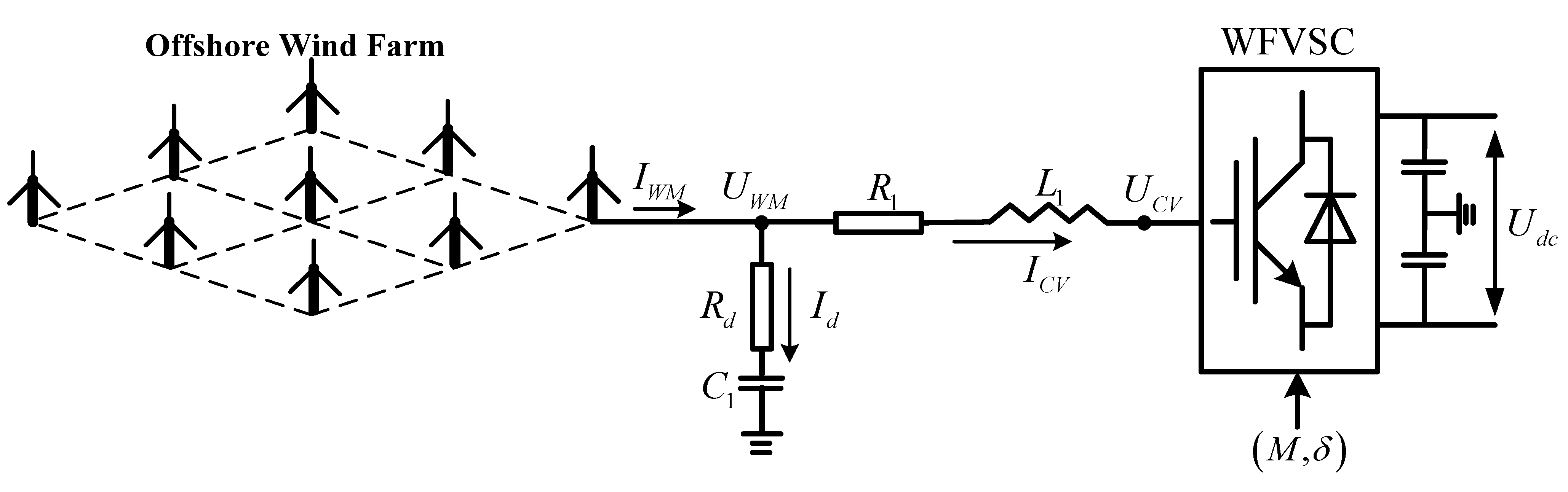
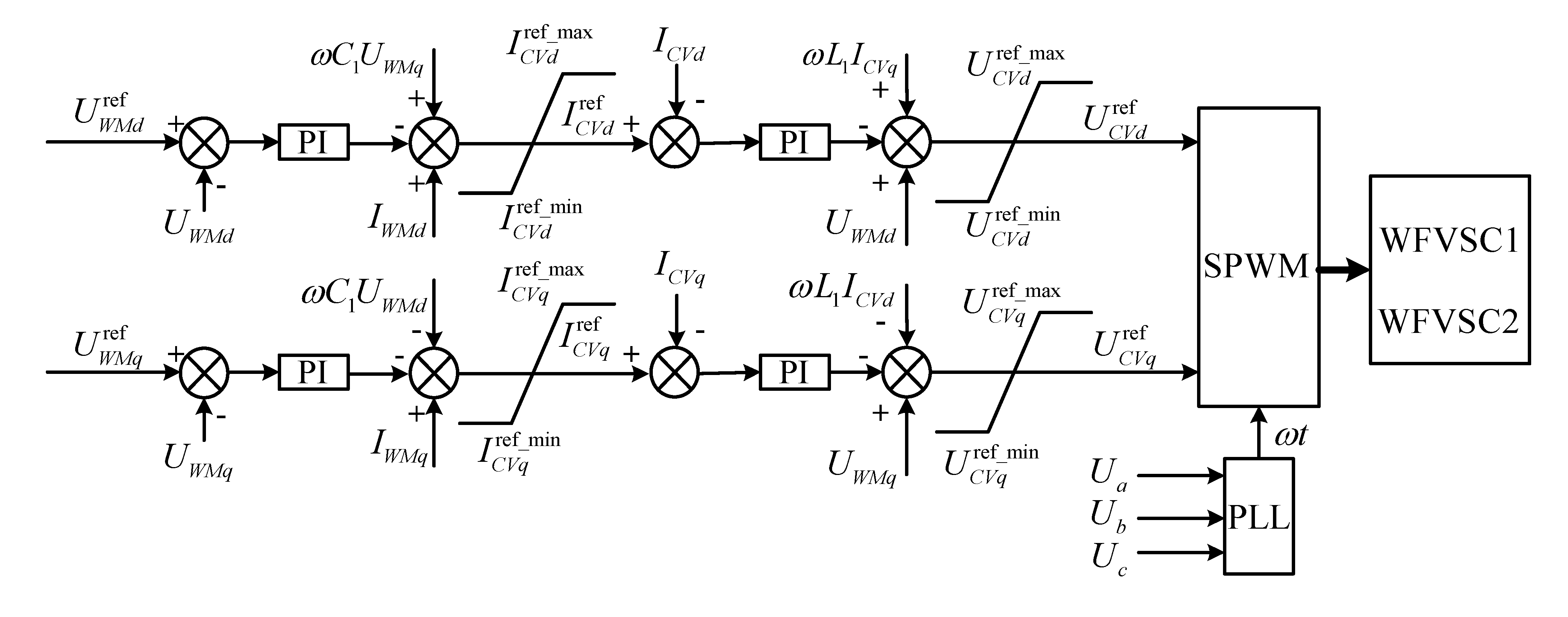
2.2.1. Control of VSC for Offshore Wind Farm

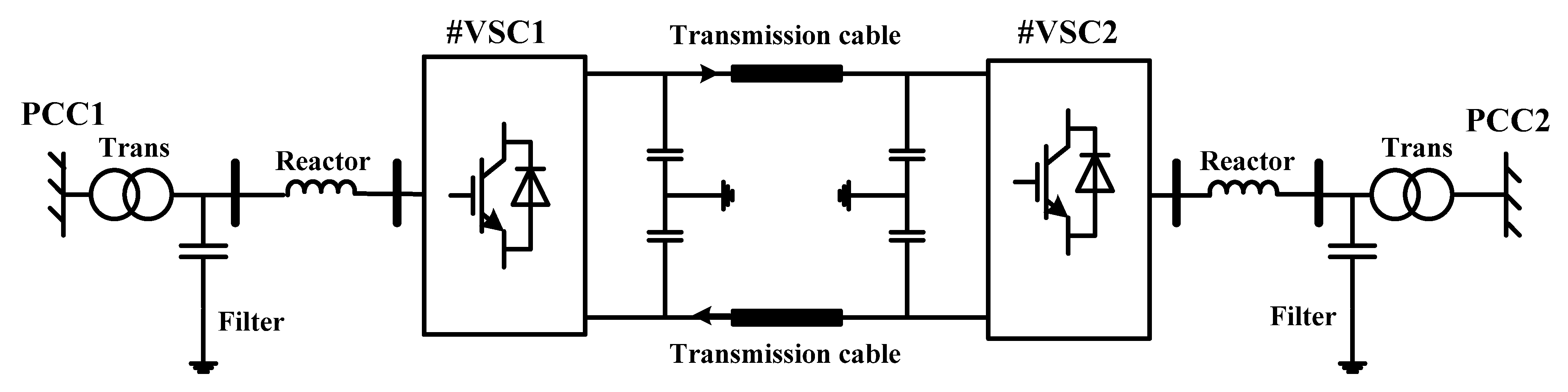
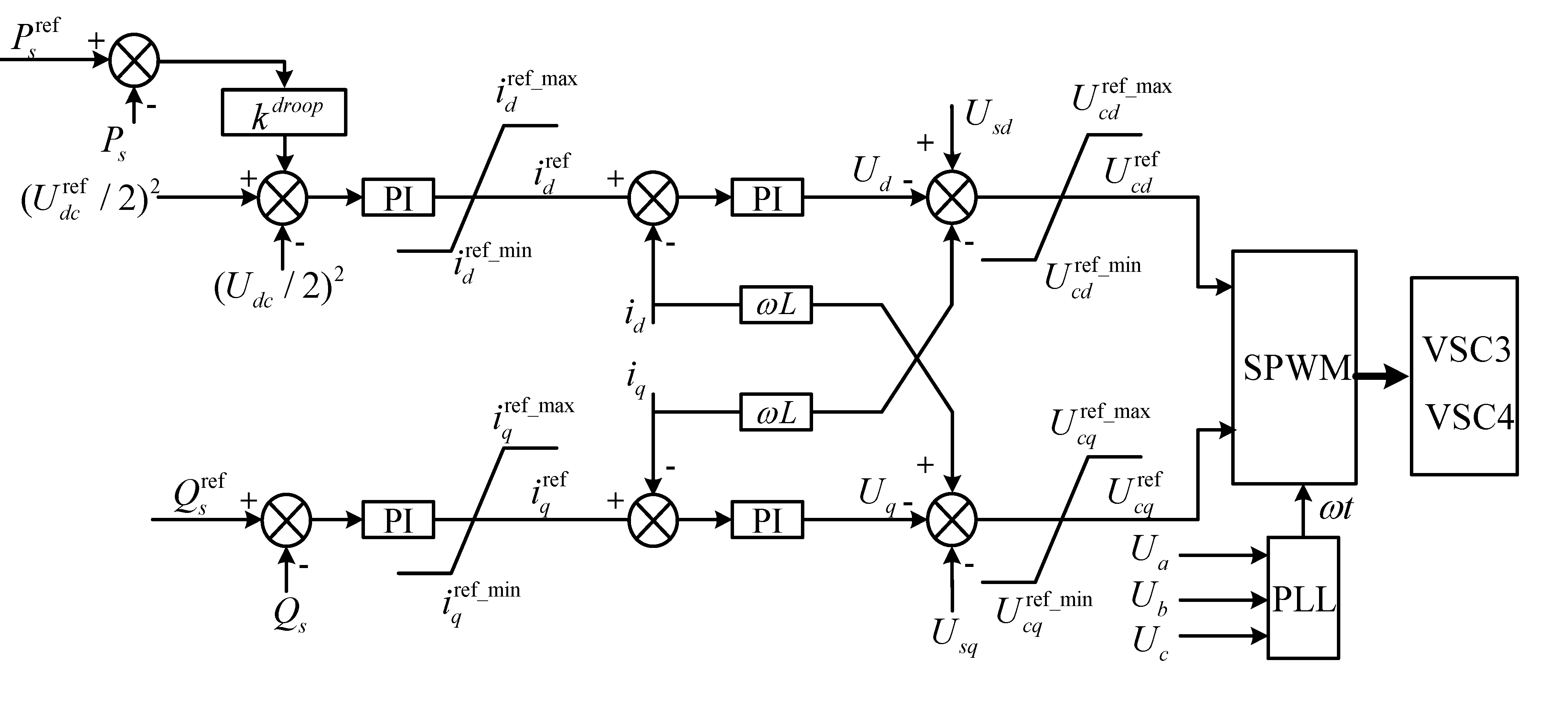
2.2.2. Control of VSC for Onshore Stations

3. Improved Adaptive Droop Control in VSC-MTDC
3.1. Fixed Droop Method
3.2. Design for Minimum Copper Loss

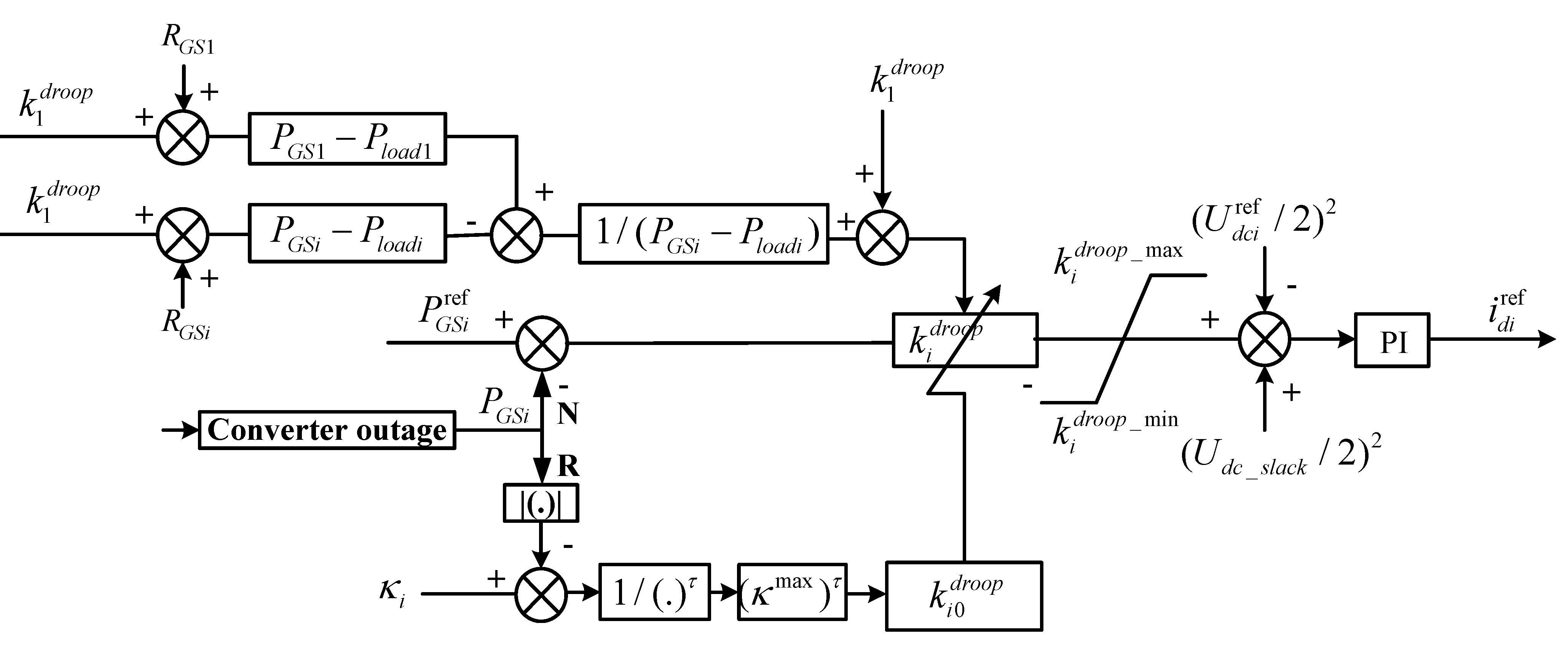
3.3. Improved Adaptive Droop Control
- (1)
- Inverter converter without local loadIn terms of inverter converter station, if , and ; if , the fundamental component of converter’s output voltage is described as followsFrom Equations (18), (20) and (22), if , thenSubstituting Equations (21) into (23), then expression of power difference coefficient of inverter stations is obtained as followsSimilarly, if , is given by
- (2)
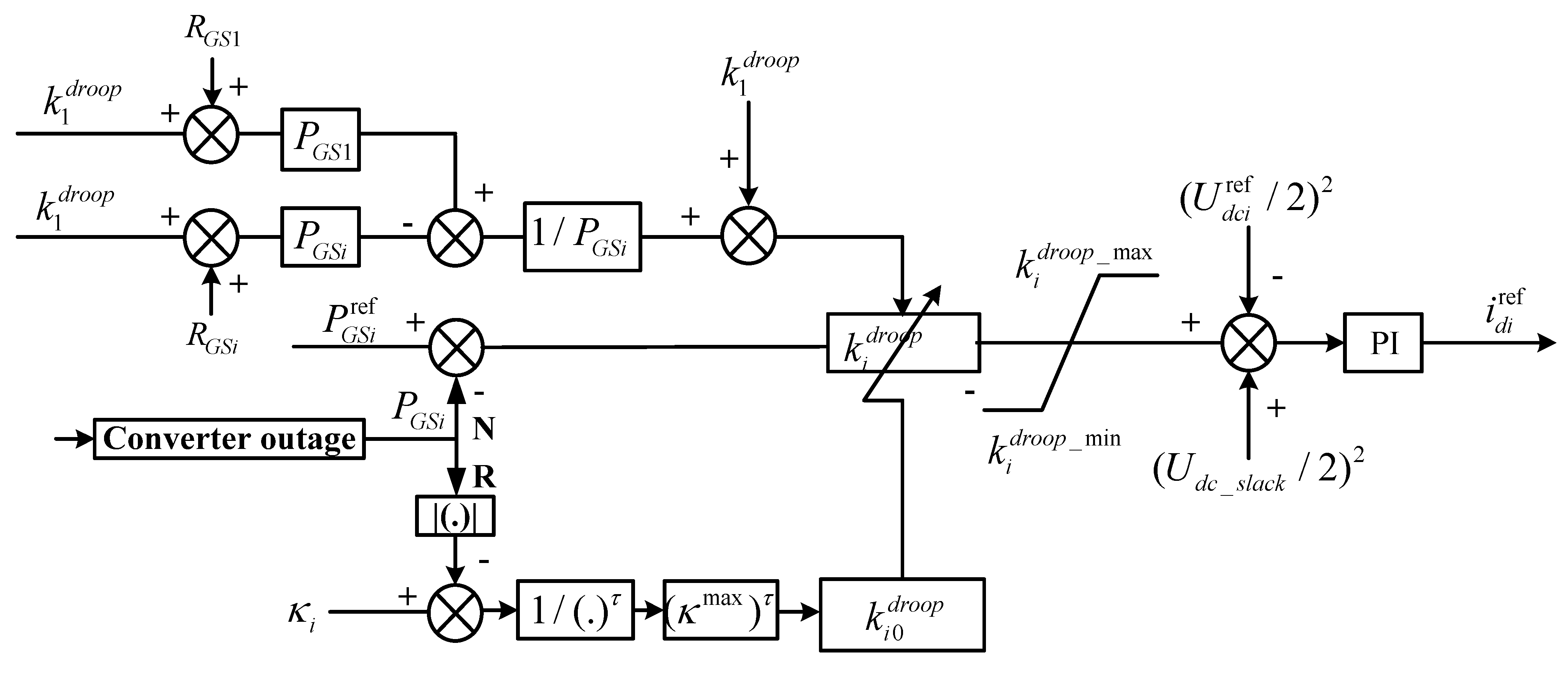
- Inverter converter with local loadAs for the first inverter converter station, if , ; if , then fundamental component of converter’s output voltage is given byIf , is shown in Equation (24). Similarly, according to Equations (18), (20) and (26), if , could be obtained as followswhere, and are local load of the first and ith inverter converter respectively; and the data of could be obtained according to communication device of system.In terms of fixed droop control, if the rating of converter stations is identical, a power imbalance caused by an outage would be shared equally with other remaining converter stations. However, some converter stations may not be able to participate in power sharing equivalently due to the actual operating condition of the system. Therefore, available headroom of the ith converter is defined as [19]where, is rated capacity of the ith converter; is remaining capacity of the ith converter; and are improved adaptive droop coefficient under pre-outage and post-outage operating conditions, respectively; refers to maximal value of all converters’ capacity; and is a user defined positive constant, whose value of and modal analysis of adaptive droop are discussed in [19].
4. Post-Contingency Operation


5. Simulation and Discussion

| Number of Cable | 1 | 2 | 3 | 4 | 5 |
|---|---|---|---|---|---|
| Resistance/Ω | 0.01085 | 0.01085 | 0.008675 | 0.016275 | 0.04 |
| Reactance/H | 0.0002 | 0.0002 | 0.00015 | 0.003 | 0.015 |
| Distance/km | 20 | 20 | 50 | 80 | 100 |
| Converters | Leakage Reactance | Capacity | Transformer Ratio |
|---|---|---|---|
| VSC1 | 0.15 (pu) | 440 MVA | 175 kV/13.8 kV |
| VSC2 | 0.15 (pu) | 440 MVA | 175 kV/13.8 kV |
| VSC3 | 0.15 (pu) | 900 MVA | 175 kV/13.8 kV |
| VSC4 | 0.15 (pu) | 400 MVA | 175 kV/13.8 kV |
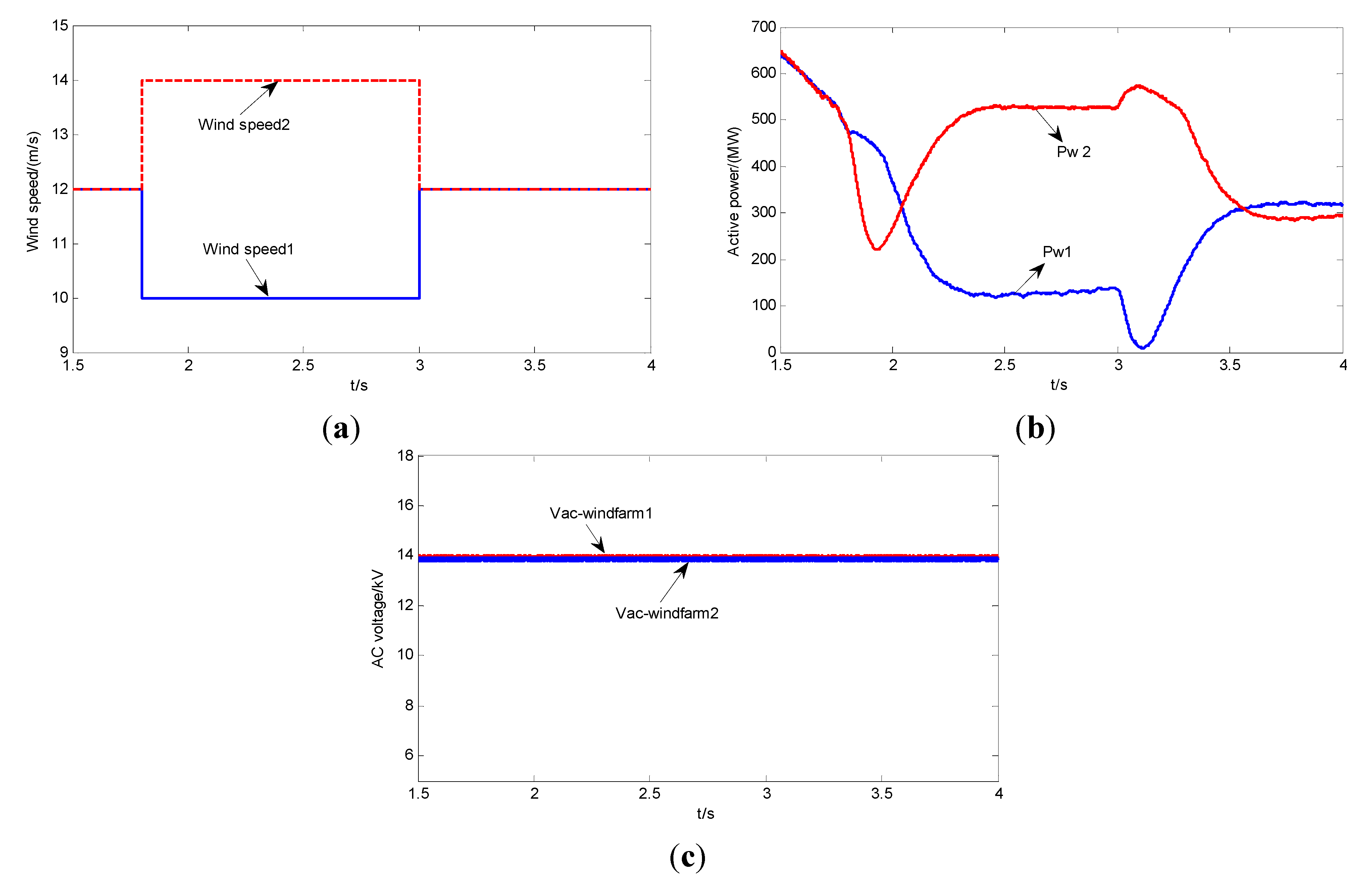
5.1. Wind Speed Variation

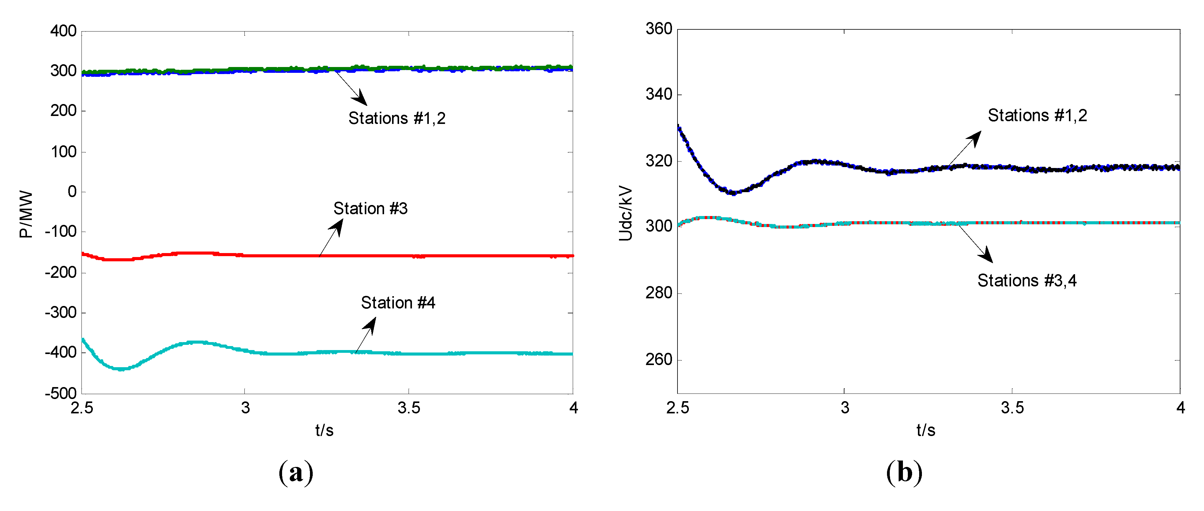
5.2. Normal Operation of VSC-MTDC
| Capacity Ratio | Droop Control | Proposed Method |
|---|---|---|
| P3ref/P4ref = 6 | 17.0368 MW [12] | 16.8933 MW |
| P3ref/P4ref = 3 | 16.8793 MW [18] | 16.7382 MW |
| P3ref/P4ref = 1 | 17.3963 MW [12] | 17.1495 MW |
| P3ref/P4ref = 1/3 | 18.1844 MW [12] | 17.8648 MW |
| P3ref/P4ref = 1/6 | 19.0705 MW [12] | 18.7209 MW |
| Capacity Ratio | Droop Control [ 12] | Proposed Method |
|---|---|---|
| P3ref/P4ref = 6 | 17.0156 MW [12] | 16.8672 MW |
| P3ref/P4ref = 3 | 16.7841 MW [18] | 16.6435 MW |
| P3ref/P4ref = 1 | 17.3718 MW [12] | 17.1211 MW |
| P3ref/P4ref = 1/3 | 18.1528 MW [12] | 17.8232 MW |
| P3ref/P4ref = 1/6 | 19.0115 MW [12] | 18.6413 MW |

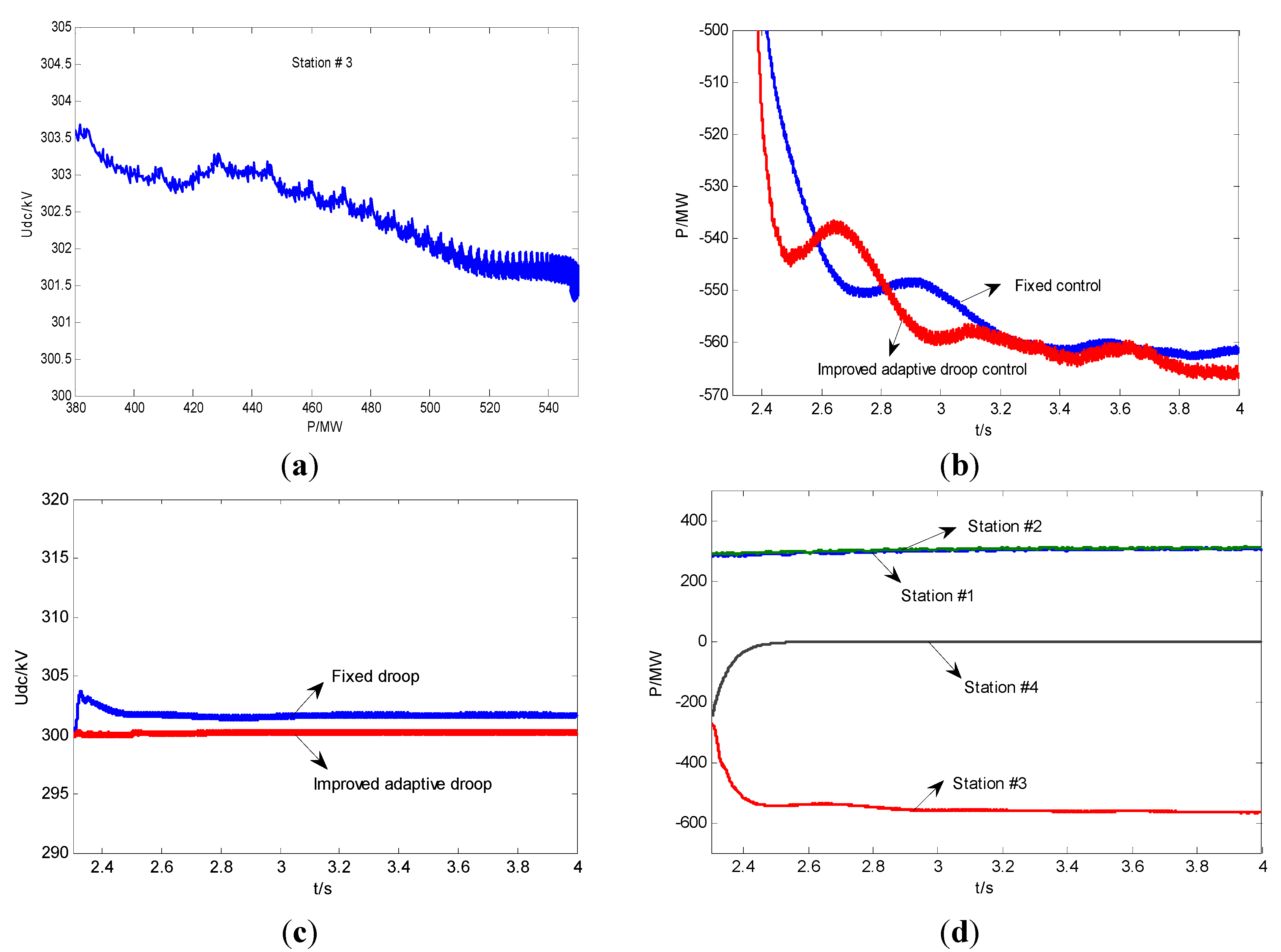
5.3. Converter Outage of VSC-MTDC
| Type | Capacity Ratio | Droop Control [19] | Proposed Method |
|---|---|---|---|
| Without local load | P3ref/P4ref = 3 | 16.7124 MW | 16.5131 MW |
| With local load | P3ref/P4ref = 3 | 16.6357 MW | 16.4265 MW |

| Type | Capacity Ratio | Droop Control [12] | Proposed Method |
|---|---|---|---|
| Without local load | P3ref/P4ref = 3 | 4.5542 MW | 4.2794 MW |
| With local load | P3ref/P4ref = 3 | 4.4991 MW | 4.2481 MW |

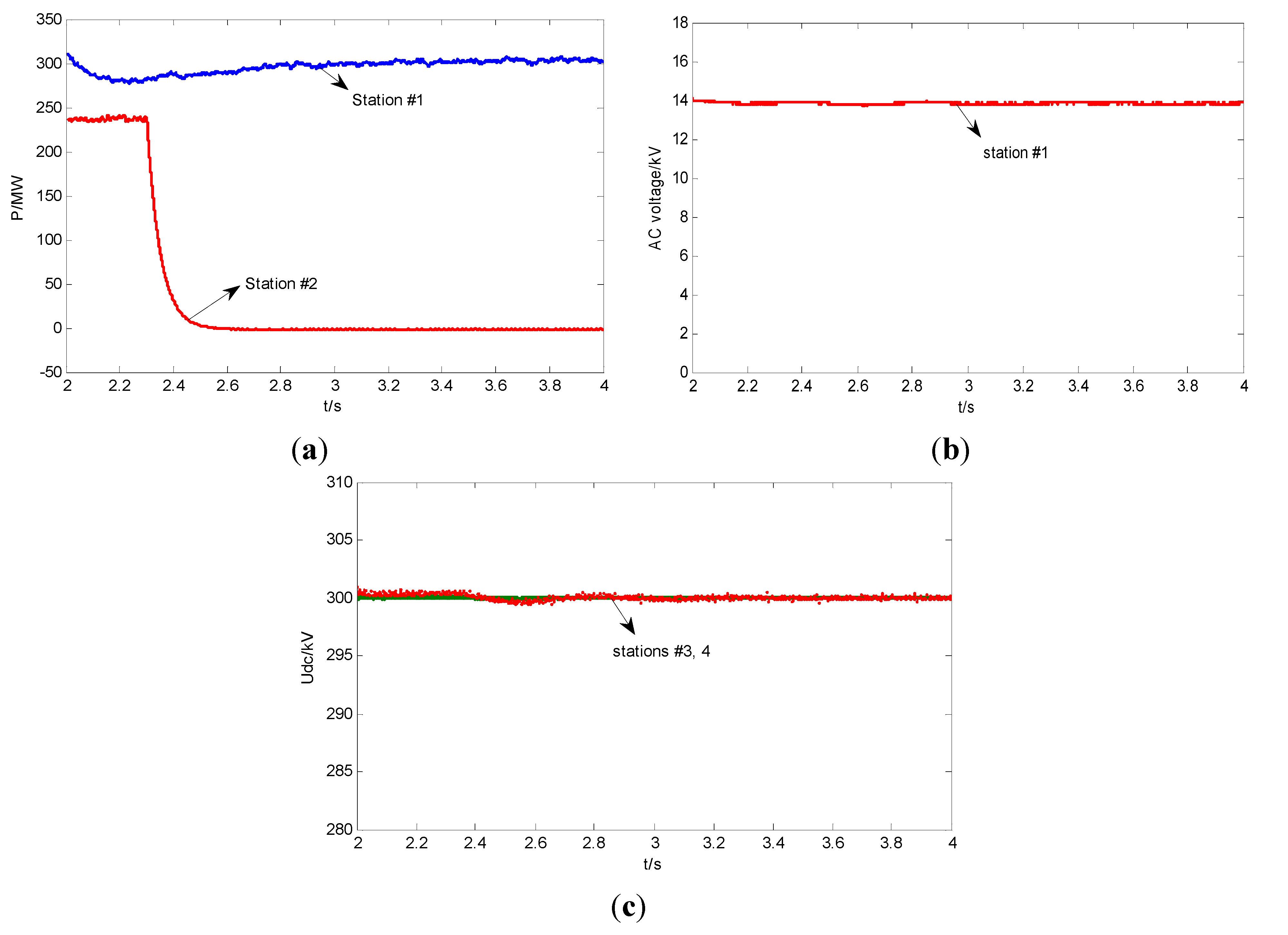
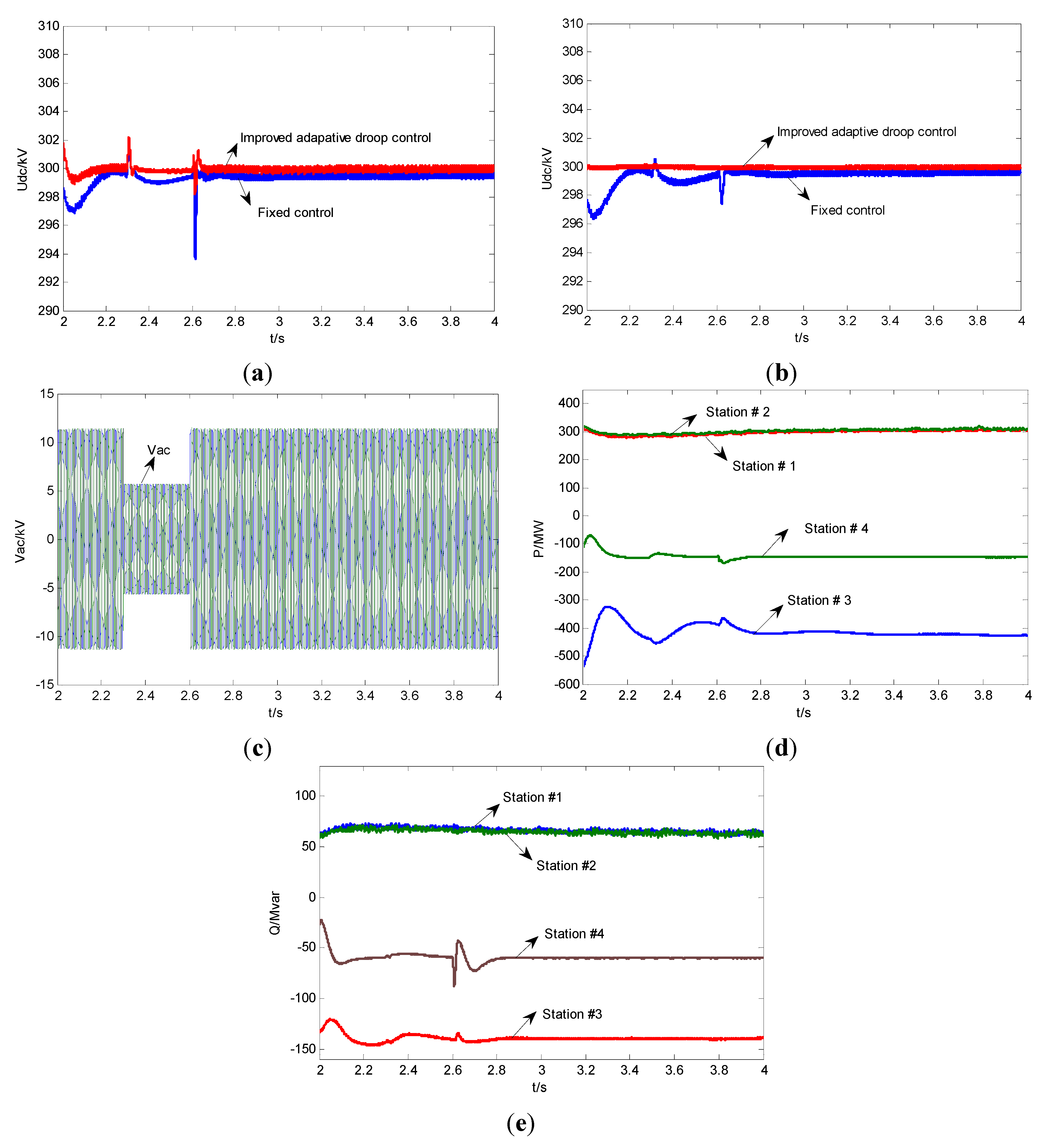
5.4. Converter Short Circuit of VSC-MTDC

6. Conclusions
Acknowledgments
Author Contributions
Conflicts of Interest
References
- ABB Group. It’s Time to Connect—Technical Description of HVDC Light Technology. 2012. Available online: http://www.abb.com/industries/ (accessed on 28 April 2015).
- Liu, Y.; Chen, Z. A flexible power control method of VSC-HVDC link for the enhancement of effective short-circuit ratio in a hybrid multi-infeed HVDC system. IEEE Trans. Power Syst. 2013, 28, 1568–1581. [Google Scholar] [CrossRef]
- Flourentzou, N.; Agelidis, V.G.; Demetriades, G.D. VSC-based HVDC power transmission systems: An overview. IEEE Trans. Power Electron. 2009, 24, 592–602. [Google Scholar] [CrossRef]
- Cole, S.; Beerten, J.; Belmans, R. Generalized dynamic VSC MTDC model for power system stability studies. IEEE Trans. Power Syst. 2010, 25, 1655–1662. [Google Scholar] [CrossRef]
- Tang, L.; Ooi, B. Locating and isolating DC faults in multi-terminal DC systems. IEEE Trans. Power Del. 2007, 22, 1877–1884. [Google Scholar] [CrossRef]
- Ludois, D.; Venkataramanan, G. An examination of AC/HVDC power circuits for interconnecting bulk wind generation with the electric grid. Energies 2010, 3, 1263–1289. [Google Scholar] [CrossRef]
- Pinto, R.T.; Rodrigues, S.F.; Wiggelinkhuizen, E.; Scherrer, R.; Bauer, P.; Pierik, J. Operation and power flow control of multi-terminal DC networks for grid integration of offshore wind farms using genetic algorithms. Energies 2013, 6, 1–26. [Google Scholar] [CrossRef]
- Chen, X.; Sun, H.S.; Wen, J.Y.; Lee, W.; Yuan, X.; Li, N.; Yao, L. Integrating wind farm to the grid using hybrid multi-terminal HVDC technology. IEEE Trans. Ind. Appl. 2011, 47, 965–972. [Google Scholar] [CrossRef]
- Silva, B.; Moreira, C.L.; Leite, H.; Lopes, J.A.P. Control strategies for AC fault ride through in multi-terminal HVDC grids. IEEE Trans. Power Del. 2014, 29, 395–405. [Google Scholar] [CrossRef]
- Beerten, J.; Cole, S.; Belmans, R. Generalized steady-state VSC MTDC model for sequential AC/DC power flow algorithms. IEEE Trans. Power Syst. 2012, 27, 821–829. [Google Scholar] [CrossRef] [Green Version]
- Nakajima, T.; Irokawa, S. A control system for HVDC transmission by voltage sourced converter. In Proceedings of the IEEE Power Engineering Society Summer Meeting, Edmonton, AB, Canada, 18–22 July 1999; pp. 1113–1119.
- Haileselassie, T.M.; Uhlen, K. Impact of DC line voltage drops on power flow of MTDC using droop control. IEEE Trans. Power Syst. 2012, 27, 1441–1449. [Google Scholar] [CrossRef]
- Yao, L.; Xu, L.; Bazargan, M.; Critchley, R. Multi-terminal HVDC grid for network interconnection and renewable energy integration. In Proceedings of the 43rd International Conference on Large High Voltage Electric Systems, CIGRE, Paris, France, 22–27 August 2010.
- Cao, J.; Du, W.; Wang, H.; Bu, S. Minimization of transmission loss in meshed AC/DC grids with VSC-MTDC networks. IEEE Trans. Power Syst. 2013, 28, 3047–3055. [Google Scholar] [CrossRef]
- Lie, X.; Williams, B.W.; Yao, L. Multi-terminal dc transmission systems for connecting large offshore wind farms. In Proceedings of the IEEE Power and Energy Society General Meeting—Conversion and Delivery of Electrical Energy in the 21st Century, Pittsburgh, PA, USA, 20–24 July 2008; pp. 1–7.
- Shu, Z.; Jun, L.; Ekanayake, J.B.; Jenkins, N. Control of multi-terminal vsc-hvdc transmission system for offshore wind power generation. In Proceedings of the 44th International Universities Power Engineering Conference (UPEC), Glasgow, Scotland, 1–4 September 2009; pp. 1–5.
- Lu, W.; Ooi, B.T. Multi-terminal HVDC as enabling technology of premium quality power park. IEEE Power Eng. Soc. Winter Meet. 2002, 2, 719–724. [Google Scholar]
- Rouzbehi, K.; Miranian, A.; Luna, A.; Rodriguez, P. DC voltage control and power sharing in multi terminal DC grids based on optimal DC power flow and voltage-droop strategy. IEEE J. Emerg. Sel. Top. Power Electron. 2014, 2, 1171–1179. [Google Scholar] [CrossRef]
- Chaudhuri, N.R.; Chaudhuri, B. Adaptive droop control for effective power sharing in multi-terminal DC (MTDC) grids. IEEE Trans. Power Syst. 2013, 28, 21–29. [Google Scholar] [CrossRef]
- Teodorescu, R.; Blaabjerg, F.; Pedersen, J.K.; Gengelci, E.; Enjeti, P.N. Multilevel inverter by cascading industrial VSI. IEEE Trans. Ind. Electron. 2002, 49, 832–838. [Google Scholar] [CrossRef]
- Su, C.W.; Jeong, I.W.; Wen, J.; Smedley, K. Drive the PMSM motor using hexagram converter. In Proceeding of the 23rd Annual IEEE Applied Power Electronics Conference Exposition, Austin, TX, USA, 24–28 February 2008; pp. 1803–1808.
- Guerrero, J.M.; García de Vicuña, L.; Matas, J.; Castilla, M.; Miret, J. Output impedance design of parallel-connected UPS inverters with wireless load-sharing control. IEEE Trans. Ind. Electron. 2005, 52, 1126–1135. [Google Scholar] [CrossRef]
- Guo, C.; Zhao, C. Supply of an entirely passive AC network through a double-infeed HVDC system. IEEE Trans. Power Electron. 2010, 24, 2835–2841. [Google Scholar]
- Abdel-Khalik, A.S.; Massoud, A.M.; Elserougi, A.A.; Ahmed, S. Optimum power transmission-based droop control design for multi-terminal HVDC of offshore wind farms. IEEE Trans. Power Syst. 2013, 28, 3401–3409. [Google Scholar] [CrossRef]
© 2015 by the authors; licensee MDPI, Basel, Switzerland. This article is an open access article distributed under the terms and conditions of the Creative Commons Attribution license (http://creativecommons.org/licenses/by/4.0/).
Share and Cite
Ran, X.; Miao, S.; Wu, Y. Improved Adaptive Droop Control Design for Optimal Power Sharing in VSC-MTDC Integrating Wind Farms. Energies 2015, 8, 7100-7121. https://doi.org/10.3390/en8077100
Ran X, Miao S, Wu Y. Improved Adaptive Droop Control Design for Optimal Power Sharing in VSC-MTDC Integrating Wind Farms. Energies. 2015; 8(7):7100-7121. https://doi.org/10.3390/en8077100
Chicago/Turabian StyleRan, Xiaohong, Shihong Miao, and Yingjie Wu. 2015. "Improved Adaptive Droop Control Design for Optimal Power Sharing in VSC-MTDC Integrating Wind Farms" Energies 8, no. 7: 7100-7121. https://doi.org/10.3390/en8077100
APA StyleRan, X., Miao, S., & Wu, Y. (2015). Improved Adaptive Droop Control Design for Optimal Power Sharing in VSC-MTDC Integrating Wind Farms. Energies, 8(7), 7100-7121. https://doi.org/10.3390/en8077100