Article

Thermal Behaviour Investigation of a Large and High Power Lithium Iron Phosphate Cylindrical Cell

MOBI—Mobility, Logistics and Automotive Technology Research Centre, Vrije Universiteit Brussel, Pleinlaan, 2, 1050 Brussels, Belgium
*
Author to whom correspondence should be addressed.
Energies 2015, 8(9), 10017-10042; https://doi.org/10.3390/en80910017
Submission received: 19 May 2015 / Revised: 28 August 2015 / Accepted: 6 September 2015 / Published: 15 September 2015

Abstract

:
This paper investigates the thermal behaviour of a large lithium iron phosphate (LFP) battery cell based on its electrochemical-thermal modelling for the predictions of its temperature evolution and distribution during both charge and discharge processes. The electrochemical-thermal modelling of the cell is performed for two cell geometry approaches: homogeneous (the internal region is considered as a single region) and discrete (the internal region is split into smaller regions for each layer inside the cell). The experimental measurements and the predictions of the cell surface temperature achieved with the simulations for both approaches are in good agreement with 1.5 C maximum root mean square error. From the results, the maximum cell surface temperature and temperature gradient between the internal and the surface regions are around 31.3 C and 1.6 C. The temperature gradient in the radial direction is observed to be greater about 1.1 C compared to the longitudinal direction, which is caused by the lower thermal conductivity of the cell in the radial compared to the longitudinal direction. During its discharge, the reversible, the ohmic and the reaction heat generations inside the cell reach up to 2 W, 7 W and 17 W respectively. From the comparison of the two modelling approaches, this paper establishes that the homogeneous modelling of the cell internal region is suitable for the study of a single cylindrical cell and is appropriate for the two-dimensional thermal behaviour investigation of a battery module made of multiple cells.

1. Introduction

Today and tomorrow, “green” cars prove to be and will be of high relevance, since they allow the solution of major environmental issues such as among others, pollution problems and noise reduction [1,2]. In the research work of Tie and Tan [3], besides the already studied ultracapacitors in [4,5,6], the flywheel energy storage (FES) and the hydrogen energy, batteries are reviewed as energy sources for electric vehicles (EVs). Indeed, with their sustainable character and reliable performances as energy storage systems, batteries represent more than ever a relevant solution for a use in the current and future electromobility [5,7,8,9,10].
To guarantee the safety and improve the lifetime of the current and future new electric and hybrid vehicles, a particular attention has to be brought to the use and the conditions of large size and high power lithium-ion batteries [11]. In automotive applications the EVs, hybrid electric vehicles (HEVs) and plug-in hybrid electric vehicles (PHEVs) are directly dependent on the embedded batteries and their performances [12]. It is therefore important to be aware of the degradation mechanisms that can affect the batteries performances and especially those caused by an excessive heat generation and an excessive temperature rise.
For lithium-ion batteries, the heat generation is especially significant [13] and can be responsible for the solid electrolyte interface (SEI) layer [14], the electrolyte and the anode decompositions [15] or the reaction of the cathode and the electrolyte [14].
Temperature also affects the batteries performances and the overall performance of an EV [16,17] and is reported to be one of the greatest factors influencing among others the lifetime, the power and energy capabilities, and the reliability of the batteries [16,18]. To avoid the occurrence of an excessive local temperature rise leading to a decrease in the lifetime of batteries or leading in the worst case to the thermal runaway phenomenon, local temperature of batteries should be carefully monitored [19]. For lithium-ion batteries, in order to guarantee both battery life and performances, the best operating temperatures are defined between 25 C [20] and 40 C [16], while long term exposure above 32 C are preferably avoided to guarantee a minimum of a 10-year lifetime [21]. For these batteries, even small temperature fluctuations are undesirable [13]. Therefore the optimisation of the battery packs or modules should be combined with the development of a battery thermal management system (BTMS), to guarantee small temperature variations within the cells and within the packs or modules [22,23,24,25]. Furthermore at the level of the packs, the non-uniformity of the temperature can cause the non-uniformity of the performances of the individual cells [18]. Hence, thermal control should be foreseen to prevent the cells during the charge and the discharge from excessive overall or localised temperature rises [13].
In the literature, thermal modelling is widely used for the study of the thermal behaviour of lithium-ion batteries. Two electro-thermal and electrochemical-thermal modelling approaches can be distinguished. The “electro-thermal” modelling approach is based on a coupling between both electrical and thermal battery models [26,27,28,29]. The “electrochemical-thermal” modelling approach consists in the coupling between the electrochemical and the thermal battery models [30,31,32,33,34]. For cylindrical batteries, thermal models can be defined in one, two and three dimensions. The internal region of the cells (or active material region) can be considered either as homogeneous (the active material is considered as a single region and is associated with a weighting of the thermo-physical properties of each layer inside the cell) or discrete (the active material is made from smaller regions defined by each layer inside the cell and their respective thermo-physical properties). Electro-thermal models are found in [26] for a one dimensional thermal analysis of a lithium iron phosphate (LFP) LiFePO 4 26650 cylindrical cell and in [27] and [28,29] for the study of a LiFePO 4 (2.3 Ah) 26650 and a LiCoO 2 (1.5 Ah) 18650 cells in two and three dimensions. Electrochemical-thermal models based on the pseudo two-dimensional (P2D) model developed by Doyle et al. [35] and Fuller et al. [36] are used in [30,31] for the study of LiMn 2 O 4 (3 Ah) and LiFePO 4 (2.3 Ah) 26650 cells and in [33,34] for the thermal analyses in two and three dimensions of LiMn 2 O 4 and LiFePO 4 18650 cells.
In these works above, the study and the characterisation of the thermal behaviour of small size cylindrical batteries with different dimensions and different chemistries were achieved, and the need for a good thermal management of these cells was also stressed. However, these works aimed at small size batteries did not consider a comparison of the results obtained with both homogeneous and discrete modellings of the internal region of the cell.
No comparable studies were addressed so far, for large size cylindrical batteries and there is a need therefore to improve the understanding of their thermal behaviour and to compare different modelling approaches of the internal region of the cell.
The purpose of this paper is to study the thermal behaviour of a large size LFP (18 Ah) cylindrical cell. In this work, the electrochemical-thermal modelling of the cell is achieved to predict the evolution of the surface temperature which was validated by experimental measurements for several charge and discharge currents rates. Two homogeneous and discrete modelling approaches of the internal region were considered and a comparison of the results was achieved for the core and the surface temperatures as well as for the temperature distribution inside the cell. Section 2 presents the methodology for this study. The electrochemical-thermal modelling of the cell and its assumptions are described in Section 3. The experimental conditions are detailed in Section 4. The validations of the electrochemical-thermal modelling of the cell voltage and the surface temperature are presented in Section 5. The evaluation of the cell thermal behaviour is addressed in Section 6 and the conclusions of this work are provided in Section 7.

2. Methodology

Figure 1 illustrates the methodology used in this paper for the study of a large size and high power LFP cylindrical cell (GAIA HP 601300 LFP) of 18Ah nominal capacity. The methodology is based on the electrochemical-thermal modelling of the cell for which the electrical, the thermal and the chemical parameters of the cell are required. The calibration and validation are based on the experimental measurements of the battery surface temperature for different constant charge and discharge currents. For the study of the temperature distribution inside the cell, two different modellings of the internal region were investigated. The first modelling approach considers the internal region of the cell (or active material region) as homogeneous. With this approach, the properties of the internal region were defined by the mean values of the thermo-physical properties associated with each layer inside the cell. The second approach consists in the discretisation of the internal region with the representation of the different layers forming the internal layered (or jelly roll) structure of the cell. For study purposes, a comparison of the results obtained with these two approaches is achieved.
Figure 1. Methodology.
Energies 08 10017 g001

3. Electrochemical-thermal Modelling of the Cell

In this study, the electrochemical modelling of the cell is based on the P2D model of Doyle et al. [35] and Fuller et al. [36]. The governing non-linear partial differential equations (PDEs) and their constitutive equations are summarised in Table 1 and describe the behaviour of the cell by means of transport phenomena and electrochemical relationships.
Table 1. Electrochemical-thermal equations.
PhysicsGoverning equationsMathematical expressions
Chemical kineticsButler-Volmer equation j L i = a s i 0 { exp ( α a η F R T ) - exp ( - α c η F R T ) }
Electrode overpotential η = ( ϕ s - ϕ e ) - U
Exchange current density i 0 = k . ( c e ) α a . ( c s , max - c s , e ) α a . ( c s , e ) α c
Charge conservationSolid phase . ( σ eff . ϕ s ) - j L i = 0
Electrolyte phase . ( κ eff . ϕ e ) + ( κ D eff l n ( c e ) ) + j L i = 0
Mass transferSpecies conservation in solid phase c s t = D s r 2 r ( r 2 c s r )
Species conservation in electrolyte ( ϵ e . c e ) t = . ( D e eff c e ) + 1 - t + F . j L i
Heat transferEnergy conservation ρ c p . T t = . ( k T ) + Q
The heat equation which describes the heat transfer phenomenon occurring between the cell and its environment is given by Equation (1):
ρ c p T t = ( k T ) + Q
where ρ represents the density, c p the heat capacity, T the temperature, k the thermal conductivity, and Q represents the heat generation. The heat generation Q inside the cell is derived from Equation (2):
Q = j L i ( ϕ s - ϕ l - U ) + j L i T ( U T ) + [ σ s eff ϕ s ϕ s + σ l eff ϕ l ϕ l + κ D eff l n ( c l ) ϕ l ]
where j L i is the transfer current due to the intercalation or deintercalation of lithium ions, ϕ s is the potential of the solid phase, ϕ l is the potential of the electrolyte phase, U is the open circuit voltage, T is the temperature, σ s eff is the effective value of the electrical conductivity of the solid phase, σ l eff is the effective value of the electrical conductivity of the electrolyte phase and c l represents the concentration of the electrolyte [34]. By definition κ D eff is given by Equation (3):
κ D eff = 2 R T σ l eff ( 1 - t + ) F
where R represents the universal gas constant equal to 8.3145 J/mol·K, T is the temperature, σ l eff is the effective electrical conductivity of the electrolyte, t + is the transference number of lithium ions and F represents the Faraday constant equal to 96,485 C/mol [34].
The first term in Equation (2) defines the reaction heat or the irreversible heat generation, the second term defines the reversible heat generation or active heat generation, while the third one (in brackets) defines the ohmic heat generation [31,33]. By definition, the reaction and the reversible heat generations are caused by the negative and the positive electrodes, while the ohmic heat generation comes from the electrolyte and both negative and positive electrodes. To convert the volumetric heat generation given by Equation (2) into a heat generation expression in W, Equations (4) and (5) [37] are introduced:
L = π N ( D + d ) 2
V i = 2 w i h L
where L represents the total length of the spiral formed by the layered internal region of the cell, N is the total number of layers inside the cell, D is the diameter at the end of the spiral (or the cell diameter), d is the diameter at the beginning of the spiral (or the internal diameter of the cell), V i is the volume of a layer, w i is the width of a layer inside the cell, h is the height of the cell and i identifies each layer.

Assumptions for Modelling and Numerical Implementations

The active materials particles of the electrodes are considered to be spherical and uniform in size for the electrochemical modelling of the cell. The migration and the diffusion for the transport of lithium ion in the electrolyte and the diffusion of these ions in the solid active material of the electrodes are considered. The side reactions were not involved in the modelling of the cell. The electrochemical reactions rates of lithium ion insertion and extraction processed are taken into account with the Butler-Volmer equation used to describe the reactions occurring at the electrodes of the cell. At the electrodes/electrolyte interfaces, electrical and chemical equilibrium is assumed. Table 2 and Table 3 summarize the electrochemcical-thermal parameters of the cell. Since the electrochemical parameters are intrinsic to the battery chemistry type, no effects due to the difference in scale between this large size cylindrical cell and the cylindrical cells in [33,38] were expected nor observed. As in Inui et al. [39], the centre of the cell was considered to be filled with air. In addition, the existence of the two external terminals of the battery cell were also taken into account.
Table 2. Electrochemical parameters.
ParametersAnodeSeparatorCathode
Thickness (m) [38]3.4 × 10 - 5 2.5 × 10 - 5 8 × 10 - 5
Active material volume fraction [38]0.580.550.374
Filler volume fraction [38]0.0326-0.0535
Volume fraction electrolyte0.38740.450.5725
Reaction rate coefficient [33]2 × 10 - 11 -2 × 10 - 11
Particule radius (m) [38]5 × 10 - 6 -5 × 10 - 8
Solid phase Li + diffusion (m 2 /s) [38]3 × 10 - 15 -5.9 × 10 - 20
Electrolyte phase Li + diffusion (m 2 /s) [38]2 × 10 - 10
Initial electrolyte concentration (mol/m 3 ) [33]2000
Maximum solid phase concentration (mol/m 3 ) [38]30,555-22,806
Table 3. Cell internal region, electrodes and separator thermo-physical properties.
Regions c p (J/kg·K)ρ(kg/m 3 ) k T ( W / m · K )
Cell internal region1034.23345.50.33434 ( k T,r )
57.515 ( k T,ang )
Negative electrode [33]1437.41347.331.04
Positive electrode [33]75036000.20
Separator electrode [33]1978.161008.980.344
Negative current collector [33]3858933398
Positive current collector [33]8752770170
In this paper, a two dimensional axisymmetric representation of the battery cell is achieved, which considers the properties of the internal region as homogeneous. Figure 2 illustrates the schematic of the cell and emphasises the different regions and their respective time invariant boundary conditions. The regions of the cell and their dimensions are as indicated in Figure 2. Initially the temperature was set to 25 C and 26 C for all the domains at the beginning of the charges and the discharges respectively. On the outer boundaries in red, an heat flux condition was set for the natural convection ( - k T = h ( T - T ambient ) ) between the cell and the ambient air. On the boundaries in blue, the heat flux continuity is considered while assuming a perfect thermal contact between the layers. On the left-hand side of the mandrel and the terminals regions, a symmetry condition for the temperature field inside the battery is applied. In Figure 2a uniform heat generation is considered in the homogeneous active material region which is computed from the 1D electrochemical heat generation expression in Equation (2).
Figure 2. Two-dimensional axisymmetric schematic of the battery.
Energies 08 10017 g002
Figure 3 illustrates the cross sectional views of both the homogeneous and the discrete representations of the cell internal structure that are studied in this paper. Figure 3b depicts the implementation of the different layers that compose the discrete internal structure of the cell. For this purpose, the discrete geometry of the internal region was made of 75 concentric spirals from 0.0045 m up to 0.0048 m inner radius and 0.0276 m up to 0.0279 m outer radius. These spirals, aimed for the representation of the jelly roll structure of the cell, were hence coerced to a solid and split afterwards into the different subdomains defined by the electrodes, the separator and the electrolyte regions. For the simulations, all the domains in Figure 3b were assigned to 25 C and 26 C initial temperature at the beginning of the charges and the discharges respectively. As in Figure 2, an heat flux condition was prescribed on the outer boundary of the cell for the natural convection phenomenon between the cell and the ambient air. Similarly the heat flux continuity was applied to the whole cell internal region, in which each of the electrodes, current collectors, electrolyte and separator layers were associated to their respective heat generations computed from Equation (2).
Figure 3. Internal representations of the cell: (a) homogeneous and (b) discrete.
Energies 08 10017 g003
The commercial finite-element solver, COMSOL Multiphysics ® (Version 4.3, COMSOL AB, Stockholm, Sweden) was chosen to develop the two internal representations of the cell (shown in Figure 2 and Figure 3) and to perform the simulations of the cell thermal behaviour. The simulations implement a MUMPS (or MUltifrontal Massively Parallel Solver) time dependent solver with an absolute tolerance of 1 × 10 - 3 for all the variables to obtain the solutions for which the mesh independency was verified. The mesh of the 2D homogeneous axisymmetric and 2D discrete representations of the cell are composed of 4495 and 314,342 elements respectively of 0.7906 and 1.049 × 10 - 4 minimum sizes. The longest simulation time to obtain the numerical solutions of a 1 I t charge or discharge process are equal to 120 s and 1080 s for the 2D axi-symmetric and discrete representations of the cell respectively.

4. Experimental Conditions

The experimental tests were defined by the recordings of the temperature at the surface of a commercially available GAIA LFP HP 601300 battery cell (diameter: 60 mm, height: 159 mm, GAIA Akkumulatorenwerke GmbH, Nordhausen, Germany) . The tests were performed at room temperature (25 C) with a 4.1 W/m 2 ·K· convection coefficient (typical for a natural convection phenomenon) that was calculated using the methodology described in Samba et al. [40]. The measurements were done using a type K thermocouple associated to maximum 2.2 C or 0.75% standard limit of error and placed at mid-height on the battery surface. From the datasheet of the cell, the voltage is recommended to stay between 2.1 V (cut-off voltage, i.e., lower limit for the voltage during discharge) and 3.8 V (maximum charging voltage). The nominal voltage and the nominal capacity specified for this cell are 3.2 V and 18 A·h (at 0.2 C) respectively. To test the cell with different current profiles and to monitor the voltage evolutions, a PEC battery tester [41] was used. The profiles were defined by 1 I t , 3 I t , and 5 I t (i.e., 18 A, 54 A, and 90 A) discharge rates and 1 I t , 3 I t , and 4 I t (i.e., 18 A, 54 A, and 72 A) charge rates. From the Standard IEC 61434 [42], the I t rate is defined by:
I t = C 1 h
where I t represents the discharge current in amperes during 1 h discharge and C is the capacity of the cell. In between the three constant current discharges (18, 54, 90 A), the battery was charged according to a CC-CV (constant current-constant voltage) mode defined with a 18 A charge step up to 3.8 V, followed by a constant voltage step keeping the battery at 3.8 V until its current drops below 0.18 A. The three charges (18, 54, 72 A) of the battery were also achieved according to the same CC-CV charge mode and were each of them followed by one 18 A constant current discharge until the battery reaches its cut-off voltage. Micro pulses have also been tested and were defined by the following steps: 2 s rest (0 A), 5 s charge at 5 I t (90 A), 2 s rest (0 A) and 5 s discharge at 5 I t (90 A). To define the micro pulse profile this sequence was repeated 142 times over a total of 2000 s.

5. Validation of the Electrochemical-Thermal Modelling of the Cell

5.1. Cell Voltage

From Figure 4, a good agreement between the experimental and the theoretical voltage curves is found for both homogeneous and discrete modelling approaches of the cell internal region. During the charge, an increase in the voltage occurs over time. This voltage increase up to 3.8 V is significantly faster for high (3 I t and 4 I t ) compared to low (1 I t ) current rates. Indeed, during the charge of the cell, the lithium ions move from the positive towards the negative electrode. From an electrochemical point of view, the rate of increase in the voltage curves depends on the solid phase lithium ions concentration c s and its maximum c s,max in the negative electrode. Therefore, the higher the charge current rate, the faster this maximum solid phase lithium ions concentration will be reached at the negative electrode and the faster the cell will be charged. During the discharge, as illustrated in Figure 4 the voltage decreases over time until the cell reaches its cut-off voltage. This decrease is significantly faster for high (3 I t and 5 I t ) compared to low (1 I t ) current rates. Indeed, because of the faster depletion of lithium ions at the negative electrode, high current rates imply a faster drop in the voltage of the cell and a more rapid discharge.
Figure 4. Voltage evolution during constant current discharges.
Energies 08 10017 g004

5.2. Cell Surface Temperature

Figure 5 illustrates the evolution of the cell surface temperature during constant current charges and discharges with an homogeneous modelling of the internal region. The curves are valid for a point located at mid-height on the surface of the cell. During the charges of the cell (Figure 5a), the surface temperature is expected to increase up to 27.3 C, 30.08 C and 30.8 C (1 I t , 3 I t , 4 I t ). The maximum temperature differences observed between the theoretical and the experimental curves are between 1 C and 1.1 C which highlights the good performance of the simulations. In the end of the discharges of the cell (Figure 5b), 26.4 C, 28.8 C and 31.4 C (1 I t , 3 I t , 5 I t ) are predicted at the surface of the cell. A maximum of 1.5 C difference is observed between the experimental measurements and these theoretical results.
Figure 5. Surface temperature evolution of the cell with an homogeneous internal region during: (a) charge and (b) discharge.
Energies 08 10017 g005
The root mean square error (RMSE) or root mean square deviation (RMSD), which is obtained with Equation (7), evaluates the accuracy of the simulations results:
R M S E = i = 1 n ( T measured - T model ) 2 n
where n represents the number of measurements and the number of simulation samples. Figure 6 indicates that for the charge and the discharge, the root mean square error made by predicting the surface temperature with the homogeneous modelling approach of the cell is less than 1 C.
In Figure 5, the faster the temperature increases, resulting from a rapid increase in the heat generated inside the cell, the less time the cell will have to properly evacuate this heat by conduction from the internal to the surface region. Because of this greater heat generation resulting in higher cell surface temperatures at high current rates, Figure 5a stresses the importance and the need for the development of a good heat and thermal management of the cell.
Figure 6. Root mean square and maximum temperature errors for both internal regions.
Energies 08 10017 g006
In contrast to the constant charge and discharge currents applied to the cell, Figure 7 illustrates the evolution of the cell surface temperature during a micro pulse load cycle. After 616 s the surface temperature of the cell is still lower than 30 C, whereas at the same time a value about 31 C was observed with a 5 I t constant discharge rate. This can be explained by the fact that the micro pulse profile is defined by the repetition of very brief 5 I t charge and discharge current rates separated with small rest periods. This profile allows for a less demanding and a more appropriate power demand to the cell and has therefore a positive impact on its thermal behaviour. With a maximum of 1 C temperature difference between the theoretical and the experimental results, Figure 7 also highlights the accurate predictions achieved by the simulations.
Figure 7. Surface temperature evolution for an homogeneous internal region of the cell during a 5 I t micro pulse profile.
Energies 08 10017 g007
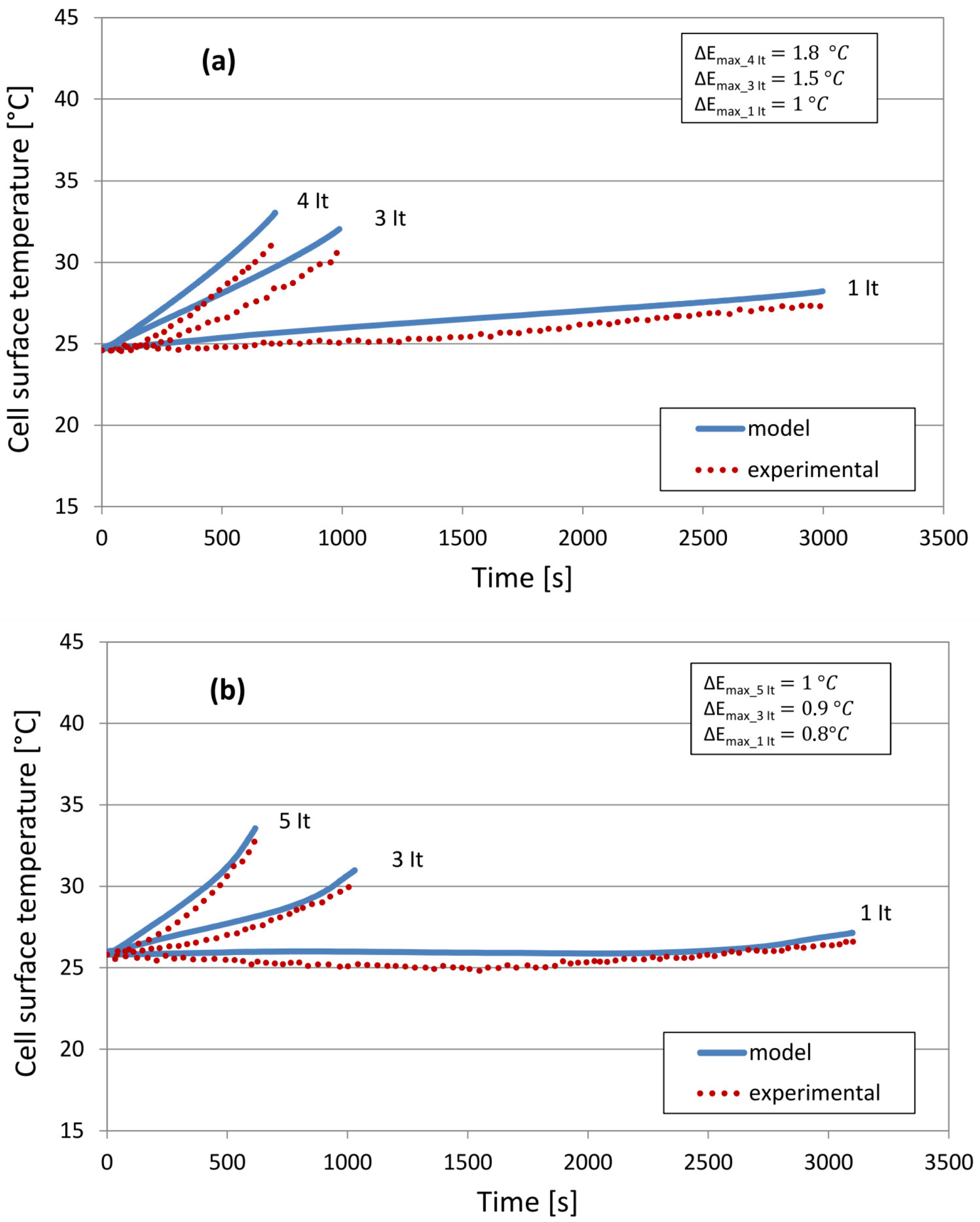
Figure 8 illustrates the evolution of the surface temperature of the cell computed with a discrete modelling of the internal region of the cell, during both constant charge and discharge respectively. In the end of the charges, the temperature is expected to be equal to 28.22 C, 32.04 C and 33.03 C (1 I t , 3 I t and 4 I t ). The maximum temperature difference between the theoretical and the experimental curves is less than 7% (or 1.8 C). In the end of the discharges, temperature at the surface of the cell is predicted to rise up to 27.13 C, 30.97 C and 33.55 C (1 I t , 3 I t and 5 I t ). During the discharges, the maximum temperature differences between the theoretical and the experimental curves are below 1 C. With the discrete modelling approach of the cell, Figure 6 indicates that for the charges and the discharges the root mean square error made by predicting the surface temperature is less than 1.5 C.
Figure 8. Surface temperature evolution of the cell with a discrete internal region for constant: (a) charge and (b) discharge.
Energies 08 10017 g008
In Figure 5 and Figure 8 slightly higher temperatures with a maximum ratio equal to 1.09 are observed during the charge compared to the discharge of the cell. This is explained in Figure 9 by the mean experimental charge to discharge resistance ratio equal to 1.12, which indicates a slightly higher resistive behaviour of the cell during its charge compared to its discharge (as also reported in [43]). This refers in the simulations to the ohmic heat charge to discharge ratios that emphasise slightly greater ohmic heat generations occurring during the charge of the cell, which lead therefore to higher temperatures when charging the cell compared to its discharge.
Figure 9. Internal resistance during charge and discharge processes.
Energies 08 10017 g009
Discrepancies in Figure 5 and Figure 8 (less than than 7% as indicated in Figure 6) are due to simulation and experimental errors. The simulation errors are linked to possible deviations in the values of the electrochemical and the thermal model input parameters (Table 2 and Table 3) of the cell. Similarly, the assumptions (introduced in Section 3.1) for the modelling of the cell, as well as intrinsic errors related to the solver for the numerical resolution of the electrochemical-thermal governing equations also contribute to the simulation errors. Regarding the measurements, a 0.75% maximum experimental error intrinsic to the thermocouple (type K to be used with the PEC SBT 0550 battery tester, PEC Products N.V., Leuven, Belgium) is supposed.

6. Results and Discussion

6.1. Evaluation of the Cell Internal Temperature Distribution

Figure 10, Figure 11 and Figure 12 illustrate the evolutions of the temperature distribution inside the cell at different state of charge (SoC) and depth of discharge (DoD). In Figure 10 and Figure 11, the internal region of the cell shows greater temperatures at 85% SoC and 85% DoD (0.86 C and 0.47 C respectively) compared to the surface region which emphasises the development of a positive temperature gradient.
Because of the lower thermal conductivity of the cell in the radial direction, a much greater temperature gradient is observed in the radial compared to the longitudinal direction.
The difference in the thermal conductivity values is explained with Equation (8) (for the cell thermal conductivity in the radial direction k T,r ) and Equation (9) (for the cell thermal conductivity in the longitudinal direction k T,ang ):
k T,r = Σ i L i Σ i L i / k T i
k T,ang = Σ i k T i L i Σ i L i
where i represents the number of layers inside the cell, L i and k T i represent the thickness and thermal conductivity of each layer. Because of the inversely proportionality of k T,r and the proportionality of k T,ang to the sum of the products of each layer thickness and thermal conductivity, the cell conductivities were found to be equal to 0.34 W/m·K and 57.51 W/m·K, respectively.
Figure 10. Temperature distributions during a 3 I t constant charge—Homogeneous internal region.
Energies 08 10017 g010
These values are different from more than 2 orders of magnitude, which explains therefore the development in time of a greater temperature gradient and a lower temperature uniformity in the radial compared to the longitudinal direction of the cell.
Figure 11. Temperature distributions during a 3 I t constant discharge—Homogeneous internal region.
Energies 08 10017 g011
In the case of a micro pulse profile, Figure 12 indicates that the temperature gradient between the internal and the surface regions of the cell reaches a value of 0.9 C after 2000 s. At the end of the simulation time, the cell shows therefore an improved temperature distribution with a lower temperature gradient in the radial direction. Hence, it is found in Figure 12 that the micro pulse profile allows for a better temperature uniformity and is therefore more appropriate to prevent from the occurrence of a large thermal imbalance inside the cell.
Figure 12. Temperature distribution at the end of a 5 I t pulse profile—homogeneous internal region.
Energies 08 10017 g012
Figure 13 investigates the thermal behaviour of the cell in the radial direction for which a low thermal conductivity value was found in Figure 10 and Figure 11.
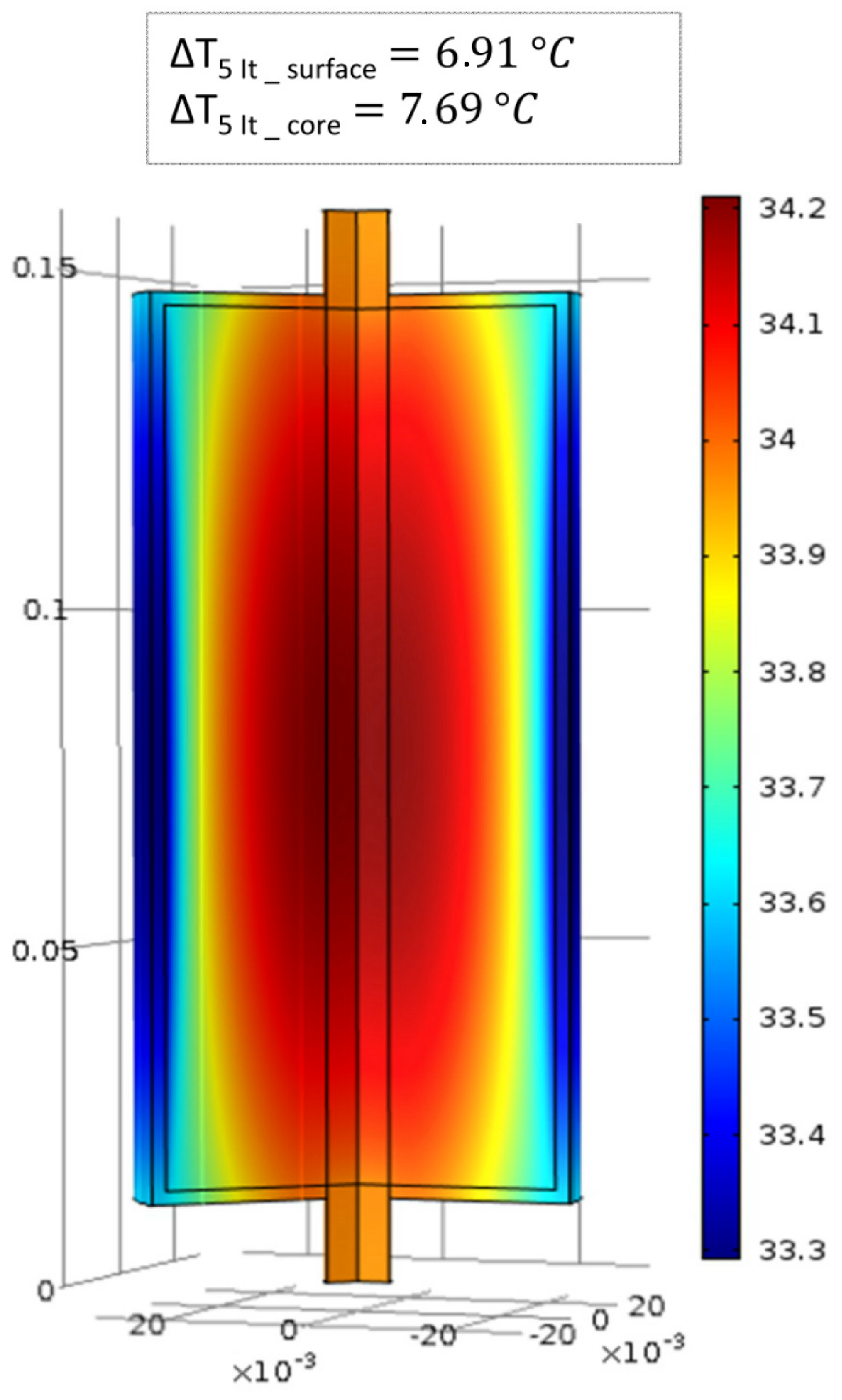
Figure 13a,c considers an homogeneous internal region obtained with a 2D axisymmetric modelling of the cell, which allows for a first estimation of the internal temperature distributions in the end of a 1 I t and a 5 I t discharge current rates. With a discrete representation of the internal region of the cell, Figure 13b,d shows an improved repartition of the temperature inside the cell and greater temperatures up to 28.4 C and 38.6 C in the core region compared to 27.4 C and 33.2 C in Figure 13a,c.
The explanation for this stems from the fact that each layer in Figure 13a,c is associated in the simulations with its thermo-physical properties and its respective heat generation determined from the electrochemical-thermal model of the cell.
With these results, Figure 13 highlights the influence of the modelling of the internal region on the temperature distribution inside the cell. From the comparison of the results, Figure 13 suggests that the identification of the areas that may be subjected to hot spots formation can differ according to the approach followed for the representation of the cell internal region.
Figure 13. Internal temperature distributions during a 1 I t and 5 I t constant discharge with (a, c) an homogeneous and (b, d) a discrete internal region.
Energies 08 10017 g013
In Figure 14, the evolutions of the temperature distribution in the radial direction of the cell are represented during both 1 I t and 5 I t discharge rates.
After 50% of its 1 I t discharge with both homogeneous and discrete approaches, almost no temperature increase is observed along the radius of the cell. In the end of the discharge, the surface and the core temperatures predicted with both approaches differ from 0.52 C and 0.94 C respectively.
In contrast to this after 50% of the discharge of the cell with a 5 I t current rate, already 3 C and 5.2 C increases are expected for the core temperature with each approach respectively. At that time, the difference between the surface and the core temperatures predicted from each approach is equal to 0.88 C and 2.2 C. In the end of the 5 I t discharge, 2.2 C up to 5.5 C differences are observed between the predictions of the surface and the core temperatures achieved by both the homogeneous and the discrete modelling approaches.
Figure 14. Temperature distribution along the radius of the cell during: (a) 1 I t and (b) 5 I t discharge.
Energies 08 10017 g014
However, with the discrete modelling of the cell internal region and the introduction of each layer and their respective thermo-physical properties, a more realistic temperature distribution in Figure 13b,d is potentially expected. Therefore to verify the validity of this assumption, the evolution in time of the core temperature of the cell obtained with the simulations has been compared to the one obtained based on analytical expressions.
For this purpose, the analytical expression for the evolution of the core temperature T c ( t ) is derived in Equation (11) from the evolution of the surface temperature T s ( t ) in Equation (10):
C s d T s ( t ) d t = T f ( t ) - T s ( t ) R u - T s ( t ) - T c ( t ) R c
T c ( t ) = C s d T s ( t ) d t - T f ( t ) - T s ( t ) R u + T s ( t ) R c
with C s being the cell surface thermal capacitance equal to 25.90 J/K, T f the ambient air temperature and R u and R c the convection and conduction resistances expressed by Equation (12) and equal respectively to 8.62 C/W and 0.92 C/W:
R u = 1 h A , R c = L k A
where h represents the convection heat transfer coefficient between the cell and the ambient air, L the length of the battery, k the thermal conductivity of the cell and A the area of the cell associated to the conduction and the convection heat transfers.
Under steady state conditions, considering the small variations of the surface temperature measured in time (less than 0.05 C/s), Equation (11) can be rewritten in Equation (13) to give the steady state expression of the core temperature:
T c = T s R u + R c R u - R c R u T f
The evolution of the core temperature obtained based on the analytical computations and the numerical simulations during both 1 I t and 5 I t discharges of the cell are illustrated in Figure 15. Figure 15a highlights the small temperature deviations (maximum 1.07 C) observed for the core temperature predicted with both discrete and homogeneous modelling of the cell. In Figure 15b, a good overall agreement (maximum 0.9 C temperature deviation) is found between the evolution of the core temperature determined analytically and the one predicted with the simulation that considers an homogeneous internal region of the cell.
Figure 15. Evolution of the core temperature during: (a) 1 I t and (b) 5 I t discharges.
Energies 08 10017 g015
With its fast computational time and the good accuracy of the results obtained for both surface and core temperatures, the homogeneous modelling of the internal region is considered appropriate for the study of the cell and further suitable for a two dimensional thermal investigation of multiple cylindrical cells inside a module as achieved in [44].

6.2. Evaluation of the Cell Temperature Rises

From Figure 16, it is found that the evolutions of the temperature with respect to the initial temperature (defined by Δ T t 0 ) are more significant during the charge (Figure 16a) compared to the discharge (Figure 16b) of the cell. This is due to the higher internal resistance (12% in mean value) of the cell during its charge compared to its discharge.
In the end of the 5 I t discharge, the maximum temperature rises for the surface and the core temperatures are equal to 5.49 C and 7.40 C in comparison to 1.13 C and 1.15 C increases in the end of the 1 I t discharge. During the discharge of the cell with 1 I t and 3 I t current rates, the maximum value for the ratio between the respective increases in the internal and the surface temperatures reaches up to 1.32. This is due to the fact that with the current rate the internal region will reach quickly greater temperatures compared to the surface region, because of the greater heat generation and the limited opportunity to exchange the heat with the ambient.
Figure 16. Temperature increases of the surface and the homogeneous internal regions for constant: (a) charge and (b) discharge of the cell. SoC: state of charge; and DoD: depth of discharge.
Energies 08 10017 g016

6.3. Evaluation of the Cell Temperature Gradients
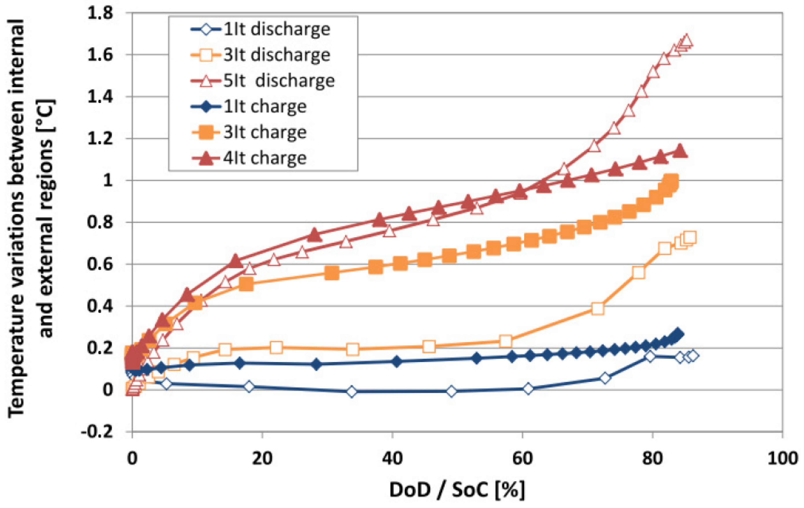
The evolutions of the temperature difference between the internal and the surface regions of the cell (defined by Δ T radial ), during the charge and discharge are shown in Figure 17. These evolutions were obtained with the homogeneous modelling approach of the internal region.
A maximum of 1.64 C temperature gradient is observed for the cell in the end of its discharge with a 5 I t current rate. In contrast to this, the temperature gradient reaches less than 0.2 C during its discharge with 1 I t . In the end of the 1 I t and 3 I t charges, the temperature gradients are 0.09 C and 0.27 C higher in comparison to those in end of the discharges. Because of the greater increase in the thermal gradients during the charge compared to the discharge of the cell, Figure 17 emphasises the importance for the development of an appropriate BTMS that guarantees a safe operating condition for the cell during the discharge and even more during the charge.
Figure 17. Temperature gradients in the radial direction of the cell during its charge and discharge.
Energies 08 10017 g017

6.4. Evaluation of the Heat Generation

Figure 18 illustrates the evolutions of the heat generation inside the cell during its discharges. With an increase in the discharge rate, the reaction heat shows greater values up to 17.4 W compared to 7 W and 2 W for the ohmic and the reversible heats. Because of the dependency to the current rate, at low discharge rates (1 I t ) the three contributions to the heat generation have the same order of magnitude (below 3 W), whereas with the increase in the discharge rate, an increase in the magnitude of each contribution occurs (below 18 W) and a more significant difference in their respective values is observed.

7. Conclusions

In this paper, the thermal behaviour study of a large size and high power LFP cylindrical cell is achieved based on its electrochemical-thermal modelling. Two homogeneous and discrete approaches were considered for the modelling of the internal region of the cell. Both approaches were validated for different constant charge and discharge currents. A good agreement with maximum 1.5 C root mean square error was found between the simulations results of the cell surface temperature and the experimental measurements. From the results, an increase up to 5.50 C and 7.40 C in the surface and the core temperatures was observed. The temperature gradients in the radial and in the longitudinal directions were equal to 0.6 C and 1.7 C due to a lower thermal conductivity in the radial compared to the longitudinal direction. From the comparison of the core temperature results with its analytical expression, a maximum 1.07 C temperature deviation was found for the results obtained with the homogeneous modelling of the cell. With its accurate results and its fast computational time, this paper emphasises therefore that the homogeneous modelling of the cell internal region is suitable for the study of a single cylindrical cell as well as for the two-dimensional thermal behaviour investigation of a battery module made of multiple cells. Inside the cell up to 2 W, 7 W and 17 W are predicted for the reversible, the ohmic and the reaction heat generations. With this paper, the need for accurate predictions of the thermal behaviour of large size cylindrical cells is highlighted, to avoid excessive temperature rises or gradients and to guarantee a safe operation especially at high current rates.
Figure 18. Ohmic, reversible and reaction heat generations during the discharges of the cell.
Energies 08 10017 g018

Acknowledgments

We acknowledge Flanders Make for the support to our team.

Author Contributions

Odile Capron and Ahmadou Samba contributed to the simulations and the writing of this paper. Peter Van Den Bossche made suggestions that contributed to improvements in the manuscript. Noshin Omar and Joeri Van Mierlo contributed to the guidance and the supervision of the research. All authors have read and approved the final manuscript.

Conflicts of Interest

The authors declare no conflict of interest.

Symbols

as
Active surface area (1/m)
c
lithium ions concentration (mol/m3)
cp
Heat capacity (J/kg·K)
d
Diameter at the start of the spiral or internal diameter of the cell (m)
D
Diffusion coefficient (m2/s)
D
Diameter taken at the end of the spiral or cell diameter (m)
F
Faraday constant, 96,485 (C/mol)
h
Height of the battery (m)
i0
Exchange current density of an electrode reaction (A/m2)
jLi
Transfer current due to the intercalation or deintercalation of lithium ions (A/m3)
k
Electrochemical reaction rate constant (m/s)
k
Thermal conductivity (W/m·K)
L
Total length of the spiral constituting the internal structure of the cell (m)
N
Total number of layers in the jelly roll structure of the cell (/)
Q
Heat generation (W/m3)
r
Radius of the spherical particle (m)
R
Universal gas constant 8.3145 (J/mol·K)
t
Time (s)
t+
Transference number of lithium ions (/)
T
Temperature (°C)
U
Open circuit voltage (V)
V
Volume of layer (m3)
w
Width of the different layers constituting the jelly roll (m)

Greek Letters

α
Charge transfer coefficient (/)
£
Volume fraction (/)
η
Overpotential (V)
κ
Ionic conductivity (S/m)
φ
Potential (V)
ρ
Density (kg/m3)
σ
Electrical conductivity (S/m)

Subscripts

a
Anode
c
Cathode
e or l
Electrolyte phase
eff
Effective
max
Maximum
measured
Measured by experiment
model
Modeled by simulation
s
Solid phase

Abbreviations

DoD
Depth of discharge
EV
Electric vehicle
FEM
Finite elements methods
FES
Flywheel energy storage
HEV
Hybrid electric vehicle
LFP
Lithium iron phosphate
MUMPS
Multifrontal massively parallel solver
PHEV
Plug-in hybrid vehicle
RMSE
Root mean square error
RMSD
Root mean square deviation
SoC
State of charge

References

  1. Van Mierlo, J.; Maggetto, G.; van de Burgwal, E.; Gense, R. Driving style and traffic measures—Influence on vehicle emissions and fuel consumption. J. Automob. Eng. 2003, 218, 43–50. [Google Scholar] [CrossRef]
  2. Maggetto, G.; van Mierlo, J. Electric vehicles, hybrid electric vehicles and fuel cell electric vehicles: State of the art and perspectives. Ann. Chim. Sci. Mater. 2001, 26, 9–26. [Google Scholar] [CrossRef]
  3. Tie, S.F.; Tan, C.W. A review of energy sources and energy management system in electric vehicles. Renew. Sustain. Energy Rev. 2013, 20, 82–102. [Google Scholar] [CrossRef]
  4. Al Sakka, M.; Gualous, H.; van Mierlo, J.; Culcu, H. Thermal modeling and heat management of supercapacitor modules for vehicle applications. J. Power Sources 2009, 194, 581–587. [Google Scholar] [CrossRef]
  5. Omar, N.; Daowd, M.; van den Bossche, P.; Hegazy, O.; Smekens, J.; Coosemans, T.; van Mierlo, J. Rechargeable Energy Storage Systems for Plug-in Hybrid Electric Vehicles—Assessment of Electrical Characteristics. Energies 2012, 5, 2952–2988. [Google Scholar] [CrossRef]
  6. Omar, N.; Gualous, H.; Al Sakka, M.; van Mierlo, J.; van den Bossche, P. Electric and thermal characterization of advanced hybrid Li-ion capacitor rechargeable energy storage system. In Proceedings of the 4th International Conference on Power Engineering, Energy and Electrical Drives (Powereng), Istanbul, Turkey, 13–17 May 2013; pp. 1574–1580.
  7. Van den Bossche, P.; Omar, N.; Al Sakka, M.; Samba, A.; Gualous, H.; van Mierlo, J. The challenge of PHEV battery design and the opportunities of electrothermal modeling. In Lithium-Ion Batteries: Advances and Applications; Elsevier: Amsterdam, The Netherlands, 2014; Chapter 11. [Google Scholar]
  8. Van den Bossche, P.; Vergels, F.; van Mierlo, J.; Matheys, J.; van Autenboer, W. SUBAT: An assessment of sustainable battery technology. J. Power Sources 2006, 162, 913–919. [Google Scholar] [CrossRef]
  9. Mulder, G.; Omar, N.; Pauwels, S.; Meeus, M.; Leemans, F.; Verbrugge, B.; de Nijs, W.; van den Bossche, P.; Six, D.; van Mierlo, J. Comparison of commercial battery cells in relation to material properties. Electrochim. Acta 2013, 87, 473–488. [Google Scholar] [CrossRef]
  10. Van Mierlo, J.; van den Bossche, P.; Maggetto, G. Models of energy sources for EV and HEV: Fuel cells, batteries, ultracapacitors, flywheels and engine-generators. J. Power Sources 2004, 128, 76–89. [Google Scholar] [CrossRef]
  11. Kim, G.; Smith, K. Multi-dimensional electrochemical-thermal coupled model of large format cylindrical lithium-ion cells. In Proceedings of the 212th ECS Meeting, Washington, DC, USA, 7–12 October 2007.
  12. Jung, D.Y.; Lee, B.H.; Kim, S.W. Development of battery management system for nickel-metal hydride batteries in electric vehicle applications. J. Power Sources 2002, 109, 1–10. [Google Scholar] [CrossRef]
  13. Braun, P.V.; Cho, J.; Pikul, J.H.; King, W.P.; Zhang, H. High power rechargeable batteries. Curr. Opin. Solid State Mater. Sci. 2012, 16, 186–198. [Google Scholar] [CrossRef]
  14. Richard, M.; Dahn, J. Predicting electrical and thermal abuse behaviours of practical lithium-ion cells from accelerating rate calorimeter studies on small samples in electrolyte. J. Power Sources 1999, 79, 135–142. [Google Scholar] [CrossRef]
  15. MacNeil, D.; Dahn, J. test of reaction kinetics using both differential scanning and accelerating rate calorimetries as applied to the reaction of LixCoO2 in non-aqueous electrolyte. J. Phys. Chem. A 2001, 105, 4430–4439. [Google Scholar] [CrossRef]
  16. Pesaran, A.A. Battery thermal models for hybrid vehicle simulations. J. Power Sources 2002, 110, 377–382. [Google Scholar] [CrossRef]
  17. Karimi, G.; Li, X. Thermal management of lithium-ion batteries for electric vehicles. Int. J. Energy Res. 2013, 37, 13–24. [Google Scholar] [CrossRef]
  18. Lu, L.; Han, X.; Li, J.; Hua, J.; Ouyang, M. A review on the key issues for lithium-ion battery management in electric vehicles. J. Power Sources 2013, 226, 272–288. [Google Scholar] [CrossRef]
  19. Sabbah, R.; Kizilel, R.; Selman, J.R. Active (air-cooled) vs. passive (phase change material) thermal management of high power lithium-ion packs: Limitation of temperature rise and uniformity of temperature distribution. J. Power Sources 2008, 182, 630–638. [Google Scholar] [CrossRef]
  20. Warner, J. Chapter 7: Lithium-ion battery packs for EVs. In Lithium-Ion Batteries: Advances and Applications; Elsevier: Amsterdam, The Netherlands, 2014; pp. 127–150. [Google Scholar]
  21. Matthe, R.; Eberle, U. The voltec system-energy storage and electric propulsion. In Lithium-Ion Batteries: Advances and Applications; Elsevier: Amsterdam, The Netherlands, 2014; Chapter 8; pp. 151–176. [Google Scholar]
  22. Pesaran, A.; Vlahinos, A.; Burch, S. Thermal Performance of EV and HEV Battery Modules and Packs; National Renewable Energy Laboratory: Golden, CO, USA, 1997. [Google Scholar]
  23. Pesaran, A. Battery thermal management in EVs and HEVs: Issues and solutions. Battery Man 2001, 43, 34–49. [Google Scholar]
  24. Pesaran, A.; Burch, S.; Keyser, M. An approach for designing thermal management systems for electric and hybrid vehicle battery packs. In Proceedings of the Fourth Vehicle Thermal Management Systems Conference and Exhibition, London, UK, 24–27 May 1999.
  25. Karimi, G.; Dehghan, A.R. Thermal analysis of high-power lithium-ion battery packs using flow network approach. Int. J. Energy Res. 2014, 38, 1793–1811. [Google Scholar] [CrossRef]
  26. Forgez, C.; Vinh Do, D.; Friedrich, G.; Morcrette, M.; Delacourt, C. Thermal modeling of a cylindrical LiFePO4/graphite lithium-ion battery. J. Power Sources 2010, 195, 2961–2968. [Google Scholar] [CrossRef]
  27. Rad, M.; Danilov, D.; Baghalha, M.; Kazemeini, M.; Notten, P. Thermal modeling of cylindrical LiFePO4 Batteries. J. Mod. Phys. 2013, 4, 1–7. [Google Scholar] [CrossRef]
  28. Jeon, D.H.; Baek, S.M. Thermal modeling of cylindrical lithium ion battery during discharge cycle. Energy Convers. Manag. 2011, 52, 2973–2981. [Google Scholar] [CrossRef]
  29. Jeon, D.H. Numerical modeling of lithium ion battery for predicting thermal behavior in a cylindrical cell. Curr. Appl. Phys. 2014, 14, 196–205. [Google Scholar] [CrossRef]
  30. Zhang, X. Thermal analysis of a cylindrical lithium-ion battery. Electrochim. Acta 2011, 56, 1246–1255. [Google Scholar] [CrossRef]
  31. Ye, Y.; Shi, Y.; Tay, A.A.O. Electro-thermal cycle life model for lithium iron phosphate battery. J. Power Sources 2012, 217, 509–518. [Google Scholar] [CrossRef]
  32. Samba, A.; Omar, N.; Gualous, H.; Capron, O.; van den Bossche, P.; van Mierlo, J. Impact of tab location on large format lithium-ion pouch cell based on fully coupled three-dimensional electrochemical-thermal modeling. Electrochim. Acta 2014, 147, 319–329. [Google Scholar] [CrossRef]
  33. Saw, L.; Ye, Y.; Tay, A.A.O. Electrochemical-thermal analysis of 18650 Lithium Iron Phosphate cell. Energy Convers. Manag. 2013, 75, 162–174. [Google Scholar] [CrossRef]
  34. Somasundaram, K.; Birgersson, E.; Mujumdar, A. Thermal-electrochemical model for passive thermal management of a spiral-wound lithium-ion battery. J. Power Sources 2012, 203, 84–96. [Google Scholar] [CrossRef]
  35. Doyle, M.; Fuller, T.; Newman, J. Modeling of galvanostatic charge and discharge of the lithium/polymer/insertion cell. J. Electrochem. Soc. 1993, 140, 1526–1533. [Google Scholar] [CrossRef]
  36. Fuller, T.; Doyle, M.; Newman, J. Simulation and optimization of the dual lithium ion insertion cell. J. Electrochem. Soc. 1994, 141, 1–10. [Google Scholar] [CrossRef]
  37. Somasundaram, K. Mathematical Modeling of Transport Phenomena in Electrochemical Energy Storage Systems. Ph.D. Thesis, Department of Mechanical Engineering, National University of Singapore, Singapore, 2012. [Google Scholar]
  38. Prada, E.; Di Domenico, D.; Creff, Y.; Bernard, J.; Sauvant-Moynot, V.; Huet, F. Simplified electrochemical and thermal model of LiFePO4, graphite Li-ion batteries for fast charge applications. J. Electrochem. Soc. 2012, 159, A1508–A1519. [Google Scholar] [CrossRef]
  39. Inui, Y.; Kobayashi, Y.; Watanabe, Y.; Watase, Y.; Kitamura, Y. Simulation of temperature distribution in cylindrical and prismatic lithium ion secondary batteries. Energy Convers. Manag. 2007, 48, 2103–2109. [Google Scholar] [CrossRef]
  40. Samba, A.; Omar, N.; Gualous, H.; Firouz, Y.; van den Bossche, P.; van Mierlo, J.; Boubekeur, T.I. Development of an advanced two-dimensional thermal model for large size lithium-ion pouch cells. Electrochim. Acta 2014, 117, 246–254. [Google Scholar] [CrossRef]
  41. PEC. Test Equipment, High Power Equipment for Cells: SBT0550. Available online: http://www.peccorp.com/SBT0550-tabs-glance.html (accessed on 12 September 2015).
  42. International Electrotechnical Commission (IEC). Secondary Cells and Batteries Containing Alkaline or Other Non-Acid Electrolytes—Guide to Designation of Current in Alkaline Secondary Cell and Battery Standards, 1996. Available online: https://webstore.iec.ch/publication/5453 (accessed on 12 September 2015).
  43. Simmons, K.; Guezennec, Y.; Onori, S. Modeling and energy management control design for a fuel cell hybrid passenger bus. J. Power Sources 2014, 246, 736–746. [Google Scholar] [CrossRef]
  44. Capron, O.; Samba, A.; Omar, N.; Coosemans, T.; Bossche, P.; van Mierlo, J. Lithium-ion batteries: Thermal behaviour investigation of unbalanced modules. Sustainability 2015, 7, 8374–8398. [Google Scholar] [CrossRef]