Abstract
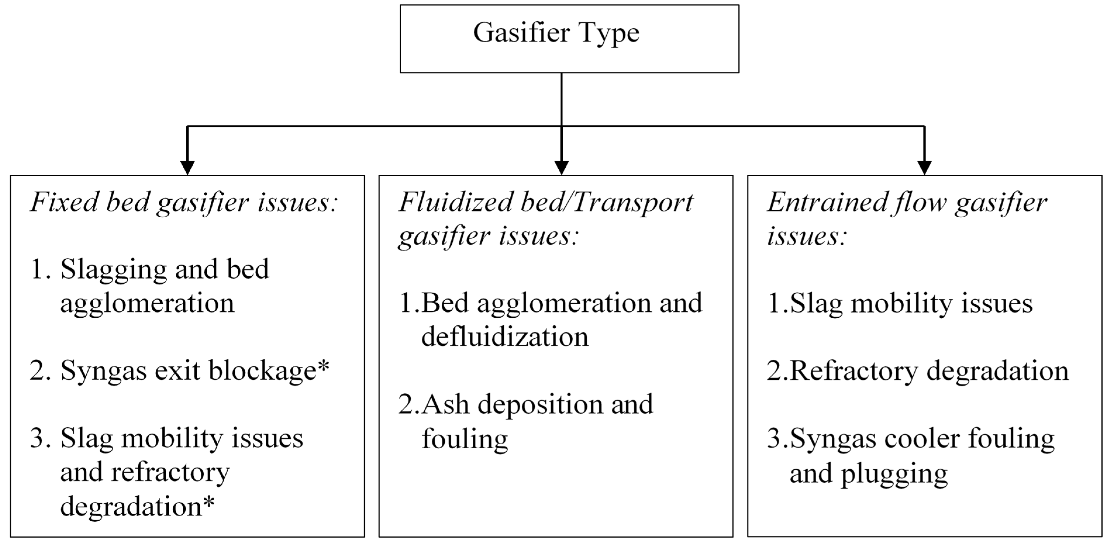
Gasification of coal is gaining more popularity due to its clean operation, and its ability to generate products for various markets. However, these technologies are not widely commercialized due to reliability and economic issues. Mineral matter in coal plays an important role in affecting the availability/reliability of a gasifier. Agglomeration in the bed, slag mobility and blockage of the syngas exit section are some of the operations related concerns in fixed-bed gasifiers, while ash deposition and sudden defluidization are the major concerns in fluidized bed gasifiers. In the case of entrained flow gasifiers, syngas cooler fouling and blockage, corrosion and erosion of refractory, and slag mobility are some of the major issues affecting the operations and the reliability of the gasifier. This review is aimed at critically examining various mineral matter related issues contributing to the operation and reliability problems in three types of generic gasifiers (fixed bed, fluidized bed and entrained flow gasifiers). Based on the review, some strategies to counter the potential mineral matter related issues are presented.
1. Introduction
Coal is a cheap and abundant natural resource for energy. However, there have been some increasing environmental and health concerns in utilizing coal [1,2,3]. Emergence of clean coal technologies is seen as a means of reducing coal’s environmental footprint [3]. Among the clean coal technologies, integrated gasification combined cycle (IGCC) provides a great promise due to its high efficiency, lower pollutant emissions, potential carbon capture and sequestration, flexibility in handling a variety of feedstock, and ability to utilize byproducts in various industries [3,4]. However, for successful operation and wide spread commercialization of these efficient utilization technologies requires an understanding and mitigation of mineral matter related issues [5,6].
Although there are numerous gasification technologies that are commercially available, these gasifiers can be broadly categorized into three main types based on the reactor bed in which coal is gasified—fixed bed, fluidized bed, and entrained flow gasifiers [7,8]. These generic types of gasifiers differ mainly in their operating conditions such as fuel particle size, fuel heating rate, temperature and fluid dynamics [9]. Table 1 compares the operating parameters for these types of gasifiers. Variation in operating conditions among these gasifier types causes difference in ways in which inorganic residues are produced and removed. Fluidized bed gasifiers operate below ash fusibility temperature (AFT) and produce dry ash. Entrained flow gasifiers operate at very high temperatures and therefore, produce vitreous slag, while fixed bed gasifiers generate dry ash or slag depending upon the design temperature [9]. The reliability of these gasifiers depends upon the generation of ash/slag in conformance to its design. Due to limited understanding of mineral matter transformations and consequent ash formation and slag deposition mechanisms, recurring mineral matter related issues have been reported in various types of gasifiers. Figure 1 shows the major mineral matter related issues in various types of gasifiers.

Figure 1.
Operation related issues due to mineral matter in various types of gasifiers (* specific to slagging fixed bed gasifiers).
Figure 1.
Operation related issues due to mineral matter in various types of gasifiers (* specific to slagging fixed bed gasifiers).
Earlier reviews on mineral matter related issues were based on combustion conditions, focused on particular kind of reactor, and focused on mechanisms [10,11,12,13]. On the contrary, this critical review focuses on major mineral matter related issues pertaining to the three types of gasifiers. The review also presents research gaps and some strategies to counter potential mineral matter issues.

Table 1.
Operating parameters of different groups of gasifiers [7,9,14,15,16,17].
| Classification | Fixed /Moving bed | Fluidized bed | Entrained flow | ||
|---|---|---|---|---|---|
| Ash conditions | Dry | Slagging | Dry | Agglomerating | Slagging |
| Typical Processes | Lurgi | BGL | HTW, CFB, HRL | KRW, U-Gas | Shell, GEE, Siemens, MHI, PWR |
| Coal Rank | Any | High | Low | Any | Any (dry feed) High (Slurry feed) |
| Particle Size | 5–80 mm | <80 mm | <6 mm | <6 mm | <100 µm (dry) <1000 µm (slurry) |
| Coal ash yield | No limit | <25% preferred | No limit | No limit | <25% preferred |
| Acceptability of fines | Limited | Injection of tuyeres | Good | Better | Unlimited |
| Operating Temperature | 973–1473 K | 1773–2073 K | 1173–1323 K | 1423–1533 K | >1573 K |
| Heating rate | Very Low (<50 K/s) | Low (<200 K/s) * | Extremely high (>10,000 K/s) | ||
| Average residence time | ~3600 s | >100 s | 0.5–10 s | ||
* heating rate during devolatilization.
2. Fixed Bed/Moving Bed Gasifiers
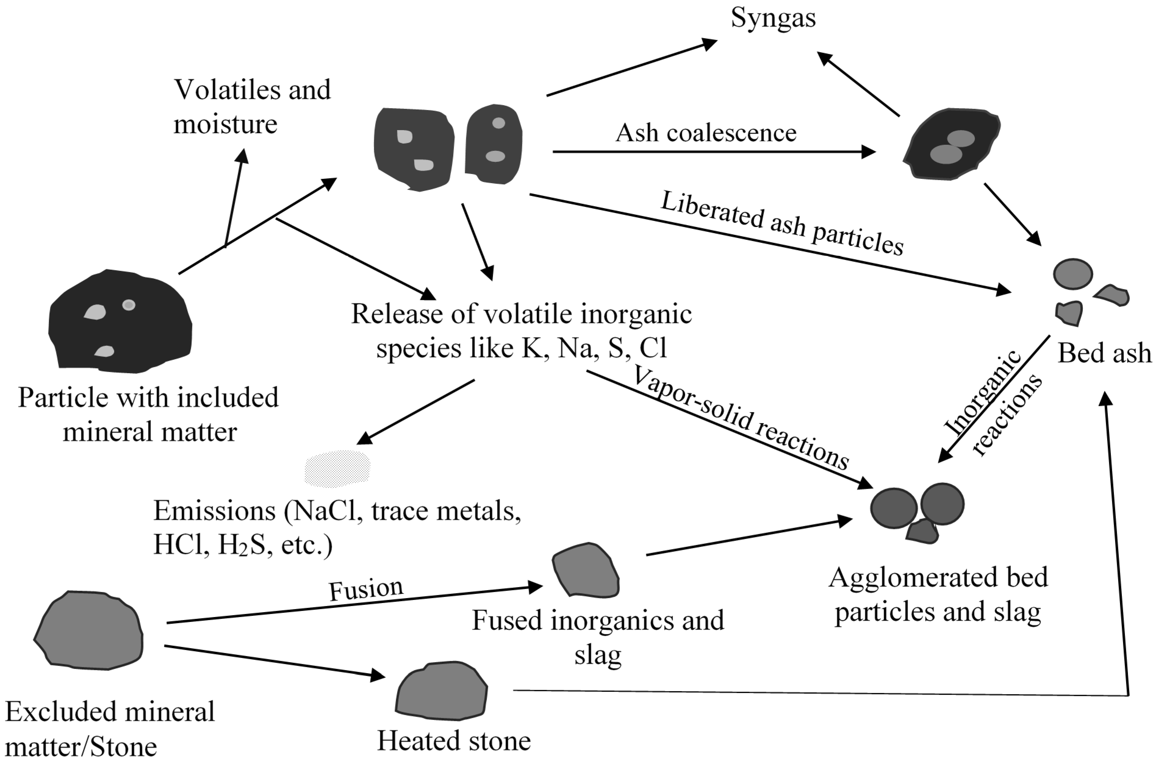
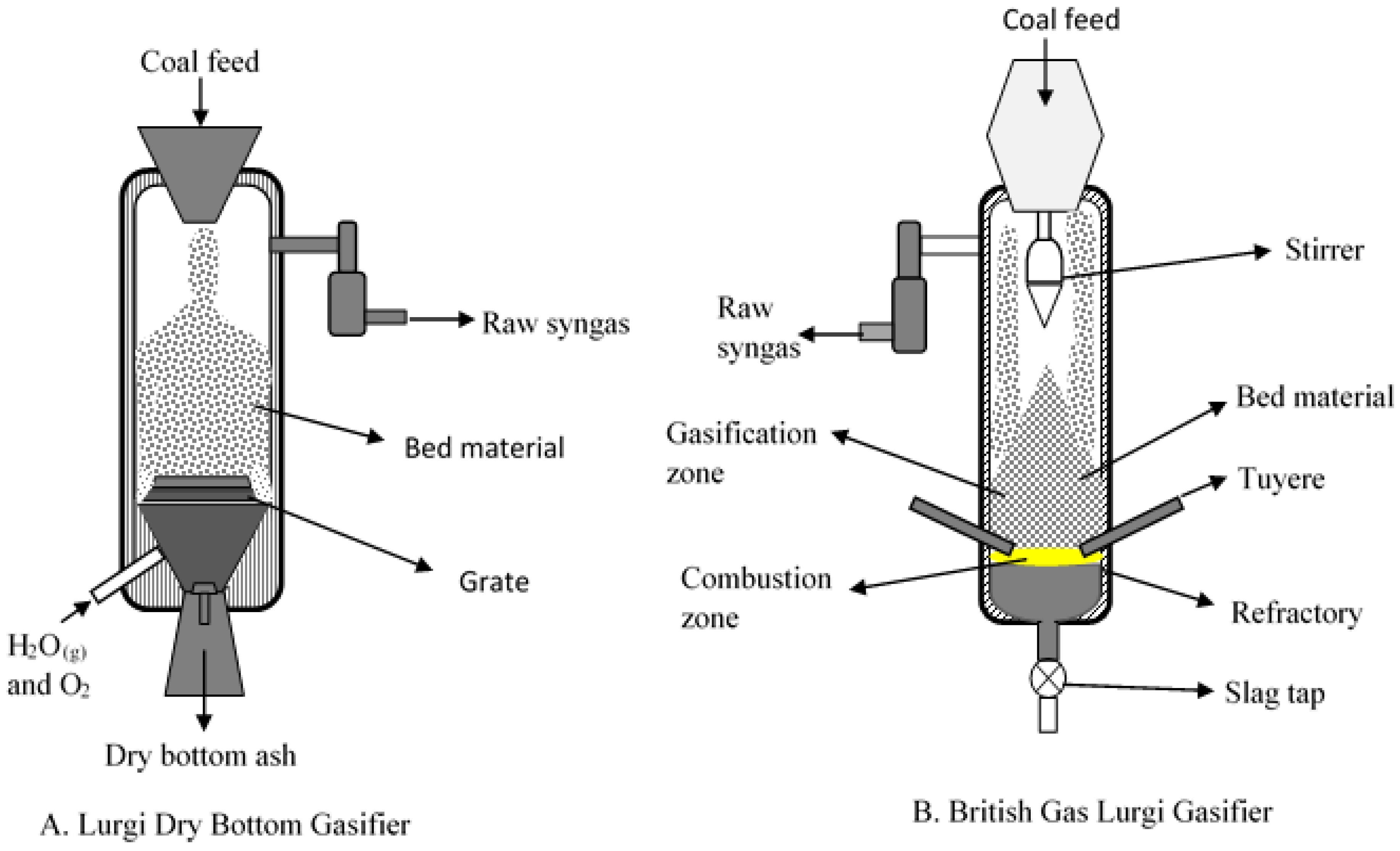
Fixed bed/moving gasifiers are characterized by the downward flow of coal particles under gravity. This type of gasifier is called fixed bed as it involves a constant bed of fuel supported by grate. The fuel above the bed is continuously replenished by the fuel fed from the top. It is also called moving bed because the particles continuously react as they move down the gasifier from the top. As the coal particle moves down, it gets preheated, dried, devolatilized, gasified and combusted due to the counter current flow of steam/oxygen mixture [7,14]. Concurrently, the inorganic species present as included mineral matter (i.e., inorganic particles surrounded by organic matrix) may either get liberated to form bed ash or undergo ash coalescence to form sticky ash during the process. The excluded mineral matter (i.e., inorganic particles with little or no association with organic matter), depending on the composition, can form sticky fused agglomerates or generate stones (less affected by temperature). Extent of slag formation in the bed is dependent on the proximity of the reactive inorganic species, oxygen potential, and the temperature prevailing in the bed. Besides included and excluded mineral matter, organically bound inorganics (i.e., inorganic elements incorporated within the organic structure as carboxylic, phenolic, hydroxyl groups, metalloporphyrins, and other organo-metallic compounds) and water-soluble inorganics (i.e., water soluble salts and other inorganic substances in the pores and surface of the coal) are released as volatile species can interact with other ash particles to form sticky ash/slag. A schematic of ash and slag formation in a typical fixed bed gasifier is shown in Figure 2. The two most popular commercially available gasifiers are British Gas Lurgi (BGL) (slagging type), and Sasol-Lurgi fixed bed dry bottom gasifiers [7]. Schematics of the Sasol-Lurgi fixed bed dry-bottom gasifier and the BGL gasifier are shown in Figure 3.

Figure 2.
A schematic of summary of mineral matter transformations and formation of agglomerates in a fixed bed gasifier.
Figure 2.
A schematic of summary of mineral matter transformations and formation of agglomerates in a fixed bed gasifier.
Mineral matter transformation and slag formation affects dry-bottom and slagging gasifiers differently. In the case of dry bottom gasifier, sufficient permeability of fixed bed is necessary for a stable operation of the gasifier [14]. The poor permeability can result in poor contact between bed fuel and the reactant gas causing channel-burning and pressure drop problems. This can lead to unstable gas outlet temperature, fluctuating gas composition risk of explosion [9,14] and thereby resulting in the reduction of gasifier load contributing to a loss in the overall efficiency. Caking properties of coal, generation of fines as a result of thermal fragmentation, particle size of the feed, and ash fusion can all contribute to poor permeability [14]. To have good bed permeability, it is desirable to have some agglomerates in the bed but too many agglomerates can affect the operation of the gasifier [14,18,19]. Therefore, understanding mineral matter transformations leading to slag formation and predicting the temperature at which the slag forms is important from the perspective of operating the gasifier.
The issue with slagging fixed bed gasifier is different. Based on the investigations during the 18 outages of the British Gas Lurgi gasifier while operating with coal and solid waste, some of the dominant issues contributing to the downtime of slagging, fixed bed gasifier were blockage of the gas exit by deposits, blockage of slag tap nozzle, and damage of refractory and tuyeres [20]. It was reported that five outages during 18 runs were due to raw gas exit blockage, while the remaining 13 outages of gasifier were due problems in the lower section of the gasifier (damage to refractory and blockage of the slag tap nozzle). One of the many outages was due to melting phases formed above tuyeres. Formation of melting phases resulted in ash agglomerates above the tuyeres affecting the oxygen and steam distribution to the gasifier. The ash agglomeration above tuyeres deflected oxygen jet causing temperature fluctuations affecting the slag viscosity and its discharge [20]. Therefore, predicting the ash fusibility and slag mobility also becomes vital for reliable operation of the slagging type gasifiers. The other issue for the slagging gasifier can be refractory degradation [21]. It is the refractory that protects external shell of the gasifier. Refractory degradation occurs in several ways—penetration of slag into refractory changes the physical and chemical properties of refractory layer resulting in the formation of cracks, direct abrasion by ash and slag, chemical dissolution of refractory by slag, spalling of refractory due to thermal fluctuations, and corrosion of refractory due to process gas [21,22]. Not much has been reported in the open literature on refractory behavior in a slagging fixed bed gasifier.
The following sections discuss inorganic interactions leading to slag formation, tools to predict slag formation, and slag mobility in slagging gasifier in more detail.

Figure 3.
Schematic of fixed bed gasifiers (A) Sasol-Lurgi Dry Bottom Gasifier (Modified after Skhonde et al. [23]); and (B) British Gas/Lurgi (BGL) Slagging Gasifier (Modified after Holt [24]).
Figure 3.
Schematic of fixed bed gasifiers (A) Sasol-Lurgi Dry Bottom Gasifier (Modified after Skhonde et al. [23]); and (B) British Gas/Lurgi (BGL) Slagging Gasifier (Modified after Holt [24]).
2.1. Role of Inorganic Interactions in Agglomerate and Deposit Formation
Alkalis play an important role in agglomeration and deposit formation during gasification. For example, agglomeration/deposition issues in both BGL gasifier and Lurgi dry bottom gasifier was reportedly due to alkalis [14,20]. Collot reported that the Lurgi dry bottom gasifier in Dakota Gasification Company (Beulah, USA) experienced formation of clinkers that filled 20% of the gasifier [14]. Formation of clinkers was attributed to the sodium species in low rank coals. This is likely due to the interaction of sodium with silica forming a melt phase. Kosminski et al. conducted studies in a small-scale tubular furnace to determine the level of interaction behavior of sodium species with silica and aluminosilicates in gasification environments [25,26]. It was observed that a portion of organically-bound sodium, in carboxylic functional groups, decomposes to form sodium carbonate, which in turn reacts with silica to form liquid sodium disilicates and other silicates at 1123 K under N2, CO2, and steam atmospheres [25]. It is important to note that the viscosity of sodium disilicate glass (Na2O·2SiO2) can be as low as ~3 Poise at 1273 K, while it increases to ~9 Poise at 823 K [27]. The low viscosity sodium silicate product could have contributed to the agglomeration and clinker formation in the Dakota Gasification Company (Beulah, USA).
Besides agglomerate formation, the alkalis and other elements associated with organic matrix are also known to cause the deposit formation [20] in the syngas exit section through vaporization and condensation mechanism. When substantial amount of alkalis are released to gas phase, the gas phase alkali species cool down in the cooler sections (syngas exit section) causing sticky deposit formation. These deposits further grow through capturing other fine particles that are entrained by the syngas and eventually resulting in the blockage of syngas exit section. It is important to recognize that the vaporization and deposition of alkalis in the syngas exit section is more relevant and applicable for slagging fixed bed gasifiers owing to their higher operating temperatures than that of dry fixed bed gasifiers where the operating temperatures are relatively lower.
In addition to alkali species, presence of pyrite and calcium carbonate in the coal can also result in slag/agglomerate formation in the fixed bed gasifier. It was reported that transformation of pyrite begins in the pyrolysis zone of a Lurgi dry bottom gasifier and disappears completely in the combustion zone [23,28]. Sulfur in pyrite is predominantly released as H2S as pyrite transforms to pyrrhotite/Fe-S-O/Fe-oxides under reducing conditions [23]. In the combustion zone where the temperature usually exceeds 1373 K, oxygen interacts with iron species to form various iron oxides. In the gasification and combustion zone, the partially oxidized iron species (Fe-S-O/Fe-oxide) from pyrite, and calcium oxide from carbonates interact with high temperature products of clay minerals to form molten iron aluminosilicates and calcium aluminosilicates at temperatures usually greater than 1273 K [23]. Other products of aluminosilicates such as sodium calcium aluminosilicates (with a melting point of ~1173 K [29]) and potassium aluminosilicates can also contribute to agglomeration of bed ash.
To determine the components that cause slag formation, Matjie et al. conducted a Computer Controlled Scanning Electron Microscopy (CCSEM) study on ash and slag (or clinker) obtained from Sasol-Lurgi fixed bed dry bottom gasifier [30,31]. The study revealed that the major difference in the composition is the amount of anorthite and glass phase present in the clinker and ash [30,31]. Interestingly, the authors reported a higher amount of interstitial and matrix glass in ash sample [30]. This suggests a possible crystallization of anorthite from the melt phase that decreased the presence of interstitial glass components in clinker. However, the formation of anorthite from melt phase is temperature dependent [31,32]. At temperatures lower than 1443 K, anorthite is formed through solid state reaction between CaO and aluminosilicate glass (meta kaolin), while at temperatures greater than 1443 K, it is formed through crystallization of melt phase during cooling [32]. In another study conducted on clinker and heated stones (from non-organic portion of the feed) from Sasol-Lurgi fixed dry bottom gasifier showed that heated stones that did not undergo any significant physical transformations was shown to have higher proportions of quartz and mullite, while clinker was shown to have the least proportions of the quartz and mullite [33]. It is important to recognize that quartz is one of the least thermally active mineral and therefore it is not surprising to be seen in the heated stones. However, presence of substantial proportions of mullite and cristobalite in heated stones is an indication of less or non-participation of fluxing agents (such as Na2O, K2O, CaO, alkali carbonates) during the transformation of clay minerals or absence of low-melting species that bind inorganic stones and ash together. It is important to recognize that mullite can also precipitate from melt phase. One can determine if the melt phase played a role in mullite formation by studying morphology and XRD of the sample and comparing the data with various predictive tools.
Agglomeration during gasification of coals appears to be initiated by the formation of eutectics. Formation of low melting species can be effectively controlled by adding suitable additives that react with components that form eutectics to yield high temperature melting species. van Dyk and Waanders [18] showed that addition of alumina by small amount (2 weight %) to ash can effectively increase ash fusion temperature. Similarly, addition of overburden and underburden of coal seam can also increase ash flow temperature [18]. It is important to recognize that determining the suitability of an additive based on ash fusion temperature may not be sufficient. This is because ash fusion test does not replicate the conditions existing in a fixed bed gasifier. Moreover, the suitability and the amount to be added are also dependent on particle size of the additive as well. Therefore, a study that simulates the fixed bed gasifier is better suited to determine the actual effectiveness of the additive.
2.2. Prediction of Slag Formation
Ash fusibility is used as an operation related parameter as it determines the operating temperature of the fixed bed gasifier especially to achieve the suitable discharge of the ash or slag [19]. Ash fusibility is determined by heating a mold made from high temperature ash (HTA) in a cone shape either in a reducing or oxidizing atmosphere at a heating rate of 8 ± 3 K/min. Temperatures associated with specific deformation of the cone are recorded and defined as: initial deformation temperature (cone begins to deform, IDT), softening temperature (cone has deformed to a spherical shape, ST), hemispherical temperature (the cone has hemispherical shape, where the diameter is equal to the height of the droplet, HT) and fluid temperature (the cone is nearly a flat layer, FT) [34]. There is a wide interval between initial deformation and fluid temperatures. The progression of initial deformation to fluid temperature is due to changes in viscosity, surface tension and other flow properties of the liquid. Significant fractions of most ashes melt at temperatures far below fluid temperature [35]. Moreover, the composition of ash and environment (oxidizing or reducing) plays important role on ash fusibility.
Ash fusion analysis is widely used in predicting slagging behavior, but it has several limitations [19,35]. One of the main limitations of ash fusion test is that it is subjective and has poor repeatability [36]. Kahraman et al. reported that the initial deformation temperature (IDT) can vary as much as 400 K when determined by two different operators [36]. Secondly, ash fusion tests carried out in laboratory conditions cannot accurately predict the melt phase in the gasifier conditions. For example, van Dyk et al. reported that only a small portion of slag was formed even when fixed bed Lurgi gasifiers were operated at temperature greater than AFT (ash flow temperature) [19]. This is likely due to a variation in the design, heating rate, residence time of ash, local gas environment, and temperature gradient in the gasifier compared to the conditions at which ash fusibility was determined. Moreover, the ash particle size distribution used in determining ash fusibility is different from that of ash particle size distribution in the gasifier. Citing van Dyk and Keyser [37], Slegeir et al. [38] reported that the coal ash fusibility characteristics were difficult to determine accurately. This is because interactions of various components in the coal ash results in not so sharp melting point like that of pure compound. Lastly and more importantly, ash fusion test gives bulk ash melting temperature and does not indicate the temperature at which the actual melting starts [35,39]. In most cases, sintering or slag formation is initiated by fluxing agents such as Na2O, CaO, Fe2+, and MgO reacting with silica/aluminosilicates/sulfur/chloride species to reduce the fusion temperatures [31,40]. During ash fusibility tests these fluxing agents will be in close proximity to the aluminosilicates/silica/sulfur/chloride, whereas in the gasifier these may not be in close proximity and hence ash fusibility test can mislead the extent of melt phase formation. Therefore, a tool better than ash fusibility is needed to better predict the initial slag formation.
Thermodynamic models can predict slag formation [37]. However, these thermodynamic models assume that the interactions of inorganic species occur under equilibrium conditions while in gasifiers, the interactions can occur under non-equilibrium conditions [41]. The other issue in using thermodynamic models for determining the slag formation tendencies is that it assumes the ash is uniformly distributed, whereas in the gasifier, the ash is not uniformly distributed and this results in inaccuracies. Although thermodynamic and viscosity modeling has limitations when used separately, it can yield significant information and especially when used with other tools. van Dyk et al. showed that thermodynamic (FACTSAGE) modeling when used along with other tools like HT-XRD can provide better insight into mineral interactions and slag formation in a fixed bed dry bottom gasifier [19]. In the case of HT-XRD, van Dyk et al. [19] observed the first sign of melt phase formation through appearance of feldspars that includes anorthite at about 1273 K which was not captured by ash fusion test. In another work, van Dyk et al. concluded that use of FACTSAGE with Urbain viscosity equation can be used to predict the temperature at which the slag forms through the slag viscosity instead of average viscosity of homogeneous phase given by Urbain equation [39]. The more accurate prediction of slag formation in the gasifier can be obtained through the combination of computational fluid dynamics model, thermodynamic model, and viscosity model. The computational model would provide us with the particle temperature and particle trajectory in the gasifier while the FACTSAGE and viscosity models can provide us with the slag viscosity. This kind of model would enable the design of the gasifier in such a way that temperature reduction can be targeted at particular section of the gasifier without reducing the temperature of the entire section of the gasifier. However, developing an accurate computational model requires (a) property data such as thermal conductivity and specific heat of ash, coal and char particles over a range of temperatures, which is missing in the literature; (b) determining the particle size distribution of ash formed during the process; (c) developing equations for particle transport within the gasifier under turbulent conditions; and (d) determining the amount of melt phase formation and viscosity required for the particles to agglomerate.
2.3. Slag Mobility in Slagging Gasifier
One of the important issues concerning slagging gasifier is the continuous discharge of slag. Crystallization or solidification of slag affects the slag discharge, which in turn affects the feed rate of coal and causing the shutdown of the gasifier [40]. A study conducted on a pilot scale slagging fixed-bed gasifier operated with a low rank coal showed that operations were generally satisfactory except for a few tests where the gasifier was stopped within 5 to 10 h of operations [42]. Interestingly, in those tests where the gasifier had to be stopped, the metallic iron was found to segregate from the slag. Schobert et al. explained the link behind iron segregation to slag discharge problems [43]. Iron(II) oxide in slag was known to reduce the viscosity of silica rich slag by acting as a flux (or network modifier). Higher concentration of metallic iron in the slag suggests that iron oxide was further reduced to metallic iron due to low oxygen concentration resulting in reduction of fluxing agent for high silica slag [43]. This increased the viscosity consequently contributing to slag discharge problems. The authors also explained that reduction of iron (II) oxide to metallic iron is not a problem with low silica (or basic) slags as there were other fluxing agents present in the slag [43]. The study also highlighted the importance of minimizing process fluctuations in the gasifier as it can significantly affect the slag discharge. In the gasifier, when the temperature increases due to other process related problems, it is usually moderated using large amount of steam. When this happens, the gasification and combustion zone temperature drops [40] and this can affect slag discharge. This is because on cooling, slag crystallization occurs which increases the viscosity substantially. The other problem that can affect the slag discharge would be the formation of bridges in the fuel bed. In this case, the oxygen will no longer be consumed in the near vicinity of tuyeres jet blast and the combustion zone of the gasifier would be shifted upwards [40]. This also results in drop in temperature along with transition of reducing conditions to oxidizing conditions near the slag tap both contributing to increased viscosity of slag and consequently leading to problems with slag discharge.
Ash composition, ash yield, and slagging characteristics at various temperatures are important from the perspective of choosing coal for the gasifier [44]. These three parameters play an important role in determining the slag tapping temperature and flux requirements [44]. Ashes that generate low viscosity slag at 1673 K under reducing conditions are preferred for this process. Nevertheless, coal generating slag with high fluid temperature can be used with fluxing agents like CaCO3 or by blending coals to keep the slag at a lower viscosity at the slag tapping temperature [44]. The rule of thumb for selecting the coal for BGL gasifier is that the slag viscosity must be 5 Pa·s at bed temperature.
3. Fluidized Bed Gasifiers
Unlike fixed bed gasifiers where there is a stationary bed, in the fluidized bed gasifiers the solid fuel is introduced along with the upward movement of gas stream, which fluidizes the bed of fuel as the reactions take place [45]. Although fluidized bed gasifiers are more tolerant to various coal ranks, non-caking coals with high reactivity and lower moisture (<18%) are preferred [40]. Fluidized bed gasifiers can be classified into two types—bubbling bed and circulating bed. The bubbling bed gasifier has the inherent limitation of not achieving higher carbon conversion due to dilution of reaction gas by the product gas and relatively shorter residence time compared to circulating fluidized bed gasifier [14,45]. The other problems with bubbling bed are entrainment of finer char particles and reduced diffusion of oxidant from bubble phase to emulsion phase [45]. These problems can be effectively overcome by using circulating fluidized bed and transport reactor. The transport reactor is markedly different from circulating and bubbling fluidized bed with respect to particle size feed, gas velocity, particle residence time, slip velocity and many other parameters [45].
Fluidized bed gasifiers operate at much lower temperatures (1173–1323 K) to avoid ash melting and agglomeration and thereby avoiding defluidization [9,14]. Unlike fixed bed gasifier, coals of any ash content can be handled without sacrificing the performance of the gasifier. Fluidized bed gasifiers differ in ash discharge conditions—dry gasifiers or as agglomerating gasifiers. In the case of dry bottom gasifiers, the portion of ash is discharged from the bottom of the gasifiers as dry ash, while in the agglomerating type gasifiers the fluidization velocity is maintained in such a way that agglomerated particles are removed without affecting the char in the gasifier [14]. Operating fluidized bed gasifiers as dry and/or agglomerating type eliminates the technical difficulties associated with slag handling and frequent refractory change [46]. This also reduces the maintenance costs, and increases the availability of the gasifier.
Despite low operating temperature, agglomeration and deposition are considered to be the major operation related problems in fluidized bed system. Unlike fluidized bed combustors, fluidized bed gasifiers can operate with bed of char and without separate bed material [6]. This means substantial portion of the ash in the bed is the result of ash generated during gasification of feed. The ash particles resulting from gasification of char particles remain in the bed or being recycled back into bed (in the case of circulating bed) or carried out by syngas as fly ash or discharged along with bed material when there is excess material in the bed as bottom ash [45]. These ash particles upon interactions with other ash particles or volatile inorganic species can form low temperature melting species resulting in ash agglomeration and bed agglomeration [10]. Agglomeration can also be the result of heterogeneous condensation of volatiles inorganic species on to the ash particles, which then undergoes agglomeration through collisions. Similarly, collisions of char particles covered by sticky inorganics formed due to ash coalescence can also contribute to bed agglomerates [10]. Once the bed starts agglomerating, the extreme case would be defluidization beyond which the plant has to be shutdown. A general schematic of ash formation and bed agglomeration is shown in Figure 4.
To understand the concept of agglomeration and defluidization, it is necessary to understand minimum fluidization velocity: One of the key parameters that used in characterizing the fluidized bed is the minimum fluidization velocity (Umf) below which the bed appears as fixed bed [45]. In order to keep the bed in fluidizing conditions, a superficial velocity (Umf ratio of volumetric flow rate of fluidizing media to bed cross sectional area) of three to five times the Umf is maintained for bubbling bed and up to 20 times the Umf is maintained for circulating fluidized bed [6]. During gasification, the partially molten ash generated is likely to attach to the surface of the bed particles due to collisions. These collisions are more frequent in a fluidized bed due to higher density of bed suspension. When the adhesive force between the bed particles due to sticky coating exceeds the segregation force of fluidization, the particles agglomerate [6]. This phenomenon is called as agglomeration. The increase in particle size and density due to agglomeration results in increased minimum fluidization velocity and superficial velocity [6]. If the minimum fluidization velocity is not increased, these agglomerated particles fall out of bed. In the event of huge amount of melt phase in the bed or at temperatures greater than ash sintering temperature, increasing the minimum fluidization velocity may not increase the segregation force over the adhesive force on the particles leading to extensive agglomeration. In the extreme case of agglomeration, the bed can no longer be fluidized and that bed is said to be defluidized. Although the mechanism of agglomeration in fluidized bed gasifier seems to be similar to that of fluidized bed combustor (FBC), the products and extent of ash/agglomerates formed can vary owing to reducing conditions.
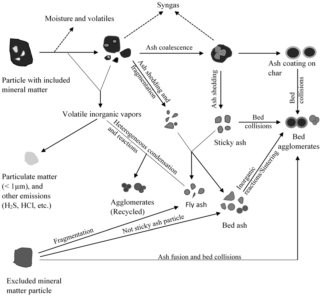
Figure 4.
A Schematic summary of mineral matter transformations and formation of agglomerates in a fluidized bed gasifier (Modified after Bartels et al. [10]).
Figure 4.
A Schematic summary of mineral matter transformations and formation of agglomerates in a fluidized bed gasifier (Modified after Bartels et al. [10]).

Besides defluidization, fouling and deposition at various sections of the gasifier can also cause operation related problems. For example, the sticky particles generated in the gasifier form deposits in the various sections of the gasifier including recirculation loop and syngas cooler, providing resistance to the flow of gas or char particles causing operation related problems [47,48]. The transport gasifier at the power systems development facility had to be stopped due to formation of deposits in the recirculation loop of the gasifier [47]. A pictorial representation of bed agglomeration and ash deposition in the various sections of the fluidized bed gasifier is shown in Figure 5.
Agglomeration and defluidization in a fluidized bed reactor is a complex phenomenon and is affected by many factors. These factors include (a) operation related parameters such as particle size, operating temperature, and fluidization velocity [6,49]; and (b) mineral matter composition [49,50,51]. All these factors affect the initial sintering temperature and/or contribute to minimum “critical thickness” of the sticky coating on the bed particles. Effect of these factors on particle agglomeration and defluidization is listed in Table 2. The following section discusses various transformations of some of the important inorganic species leading to melt phase formation, agglomeration and ash deposition.

Figure 5.
A pictorial representation of bed agglomeration, and ash deposition in a fluidized bed gasifier.
Figure 5.
A pictorial representation of bed agglomeration, and ash deposition in a fluidized bed gasifier.
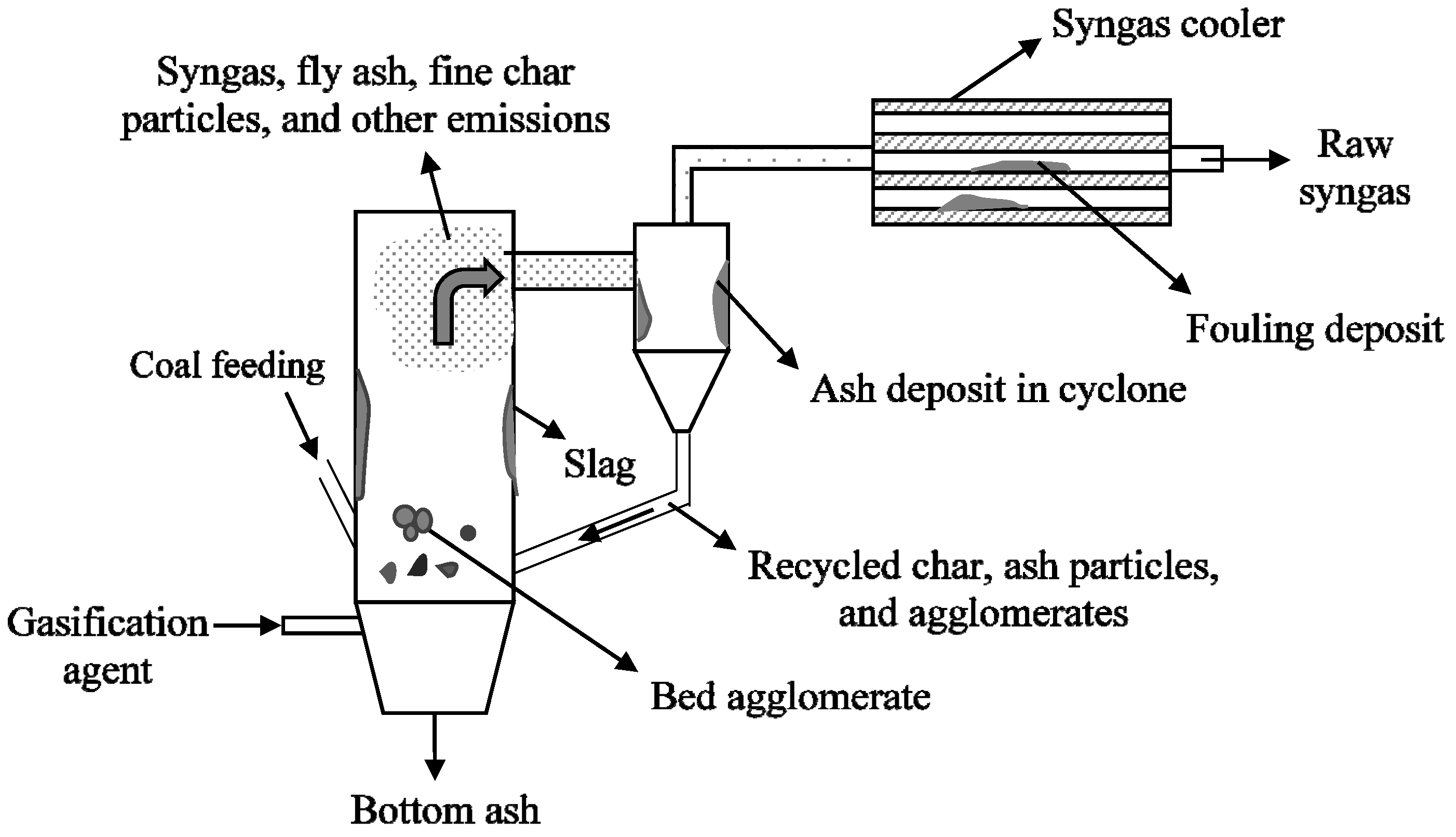
Table 2.
Effect of operation parameters on agglomeration and defluidization [25,49,52].
| Factors | Effect on agglomeration and defluidization |
|---|---|
| Temperature | Increase in temperature increase the possibility of agglomeration and defluidization |
| Particle size distribution | Presence of a bimodal or multimodal particle size distribution increase the possibility of agglomeration and defluidization |
| Fluidization velocity | Increase in fluidization velocity increases the segregation force and reduce the agglomeration tendencies below ash sintering temperature |
| Alkalis, iron sulfides, and siderite | Increase the possibility of agglomeration and defluidization through formation of melt phase |
| Steam | Increase in steam can increase the agglomeration and defluidization |
3.1. Mineral Matter Transformations Leading to Agglomeration and Deposition
Fluidized bed gasifier operates relatively at a low temperature and therefore a highly reactive fuel is preferred for maintaining a high feed rate [14,45]. Low rank coals are usually considered for fluidized bed due to their high reactivity. But the issue is that low rank coals have significant amounts of thermally reactive organically-bound sodium, calcium, magnesium elements, and water-soluble inorganic species [40]. These species can significantly affect the operation of the gasifier due to their ability to form low melting eutectics at the operating temperature of the gasifier [48]. The chemistry of melt phase formation is complex and varies depending upon the ash components and the operating conditions.
Formation of melt phase during gasification of low-rank coal is facilitated by reactions of the organically bound inorganics and water-soluble inorganics. Kuo et al. reported little less than 1 weight % of sodium concentration in the feed is high enough to cause defluidization in a fluidized bed gasifier [52]. Kosminski and Manzoori [48] also reported that sodium played an important role in formation of fused agglomerates when a low-rank coal was gasified in a HTW (High Temperature Winkler) gasifier. Similarly, Dahlin et al. reported that the transport gasifier was stopped when operating high sodium lignite due to deposit formation in the recycle cyclone causing the blockage of recirculation of solids [47]. In both the cases formation of low melting sodium silicates was suspected to cause agglomerates within the gasifier. The formation of molten sodium silicates can be explained as follows: The sodium in low rank coals is primarily attached to carboxylic groups or can exist as chlorides. Upon exposure to fluidized bed conditions (at high temperature), the sodium with the carboxylic group may chemically dissociate from the char structure to form sodium carbonate [53,54]. Sodium carbonate thus formed can react with silica to form sodium silicates glass (xNa2O·ySiO2 x = 1 or 2; y = 1 to 3.75) [25]. Under fluidized bed gasifier conditions, formation of sodium disilicate glass (m.p. of 1147 K) is thermodynamically favorable [25]. The formation of molten sodium disilicate can be either through solid-solid reaction (in CO2 and N2 atmospheres) or through liquid–solid reaction (in steam atmosphere) as shown here:
Solid-solid reaction (in CO2 and N2 atmospheres) at temperatures <1123 K:
Liquid-solid reaction (in steam atmosphere) at temperatures >1023 K:
Sodium disilicates formed through solid-solid reaction is slow, while the sodium disilicates formed through solid–liquid reaction is faster. It can be concluded that presence of steam in the gasifier promotes agglomeration and defluidization by increasing the rate of formation of sodium disilicates.
Besides sodium carbonate, presence of sodium chloride can also contribute to sodium disilicates. However, this occurs only in presence of steam [25] at fluidized bed operating temperatures (~1123 K) through following reaction:
It was also proposed that sodium from sodium chloride can also get converted to sodium carbonate through reaction with carboxylic groups. This sodium carbonate in turn reacts with silica to form liquid sodium silicates as explained earlier. However, the rate of formation of sodium silicates through this route is slow [25,55].
The analysis of the deposits within the gasifier and in the downstream showed halite to be one of the major fouling components [48]. Besides sodium chloride, NH4Cl was also observed in the deposits obtained from syngas cooler. The authors attributed the occurrence of NaCl and NH4Cl near the syngas cooler to sudden cooling of gases resulting in condensation of those species [48]. NaCl present as water-soluble inorganics is usually released as Na and Cl separately [55,56,57]. Therefore, NaCl observed in the syngas cooler might have been a secondary product (not directly released from coal particle). Besides NaCl, the report also pointed out the possible presence of FeCl3 and CaCl2 in the syngas cooler deposits [48]. In the case of FeCl3 and CaCl2, this is likely to have formed through interaction of their corresponding oxides (FeO and CaO) with HCl vapors in the cooler sections of the gasifier as FeCl3/CaCl2 are highly unstable at temperatures (~1173 K) prevailing in the gasifier. The significance of chloride species particularly NaCl, CaCl2, FeCl3 and NH4Cl in the syngas cooler is that it can exist in molten phase individually or through formation of eutectic mixture.
The other important mineral in coal that plays a role in agglomeration is pyrite. Unlike sodium species, which are predominantly found in low-rank coals, pyrite occurs across a wide range of coal ranks. Several studies have reported the role played by pyrite derived ash particles in agglomeration under fluidized bed conditions [58,59,60]. Mason and Patel conducted a study to determine the chemistry of ash agglomeration in a U-Gas pilot scale fluidized bed gasifier [60]. Analysis of agglomerates derived after gasifying a run-of-mine Kentucky coal showed that the coating had the presence of calcium aluminosilicates, iron silicate and ferrous sulfide with small amount of calcium-iron-silicate and magnetite. It was also noted that most of the agglomerates (3/4th of the agglomerates) were covered by low melting iron rich coating. This coating increases the surface contact and consequently the agglomerations. The ash agglomeration in the gasifier was suggested to be very much dependent on oxidation state of iron. Based on the ash fusibility tests, the study observed that pyrite is more problematic under slightly reducing environment where it exist as FeO-FeS (liquid formation temperature ~1200 K) and less problematic under extreme oxidizing (exist as Fe2O3 or Fe3O4) or in extremely reducing environment (exist as Fe) [60]. The authors concluded that the partial oxidation of ferrous sulfide (to FeO) is prerequisite for the formation of low-melting phase resulting in agglomerate formation [60]. A more recent study pointed out that mineral matter rich fractions of coal containing pyrite is likely to initiate slag and agglomerate formation in a fluidized bed gasifier [61]. This is because iron oxide embedded in organic rich feed particles can initiate agglomerate formation only at higher conversion.
Unlike pyrite and alkali species, calcium oxide is preferable in fluidized bed gasifiers. This is because of its ability to capture sulfur. Deposits obtained from HTW gasifier showed the presence of CaS, CaCl2 and monticellite [48]. It was suggested that CaS was formed as a result of interactions between CaO with H2S [48]. The formation of CaS could have formed while CaO particles are in the bed or after deposition by interacting with H2S. In the absence of H2S, presence of free lime can be problematic in the low-temperature region as it can strengthen the deposits by forming Ca(OH)2 and carbonates through interaction with steam and CO2, respectively [62]. Moreover, it can be problematic when chlorine content in coal is significant. This is because of formation of CaCl2, which has a low melting point.
3.2. Strategies to Minimize Agglomeration and Ash Deposition
The root cause to the problem of agglomeration and fouling is the formation of low melting eutectics [51]. The low melting eutectics are usually a product of interactions among alkali species, sulfur species and bed particles (usually silica) in the case of low-rank coals [25,40], while pyrite derived ash play an important role in agglomeration in the case of high-rank coals [58]. More than the presence of low-melting eutectics, it is also the amount of low-melting eutectics that determine the stickiness. Particles are usually assumed to be not sticky with molten phase less than 15 weight %; while 70 weight% of melt phase is considered to be completely sticky [63]. To reduce the extent of sticky phase formation, alkalis and chlorine species particularly from low-rank coals have to be reduced. The general rule of thumb for fouling developed for low-rank coal combustion also applicable for gasification is that coal is low fouling, medium fouling and high fouling if concentration of sodium (% dry coal basis) is <1%, 1%–5%, and >5%, respectively [40]. When dealing with medium and high fouling coals, various corrective measures have to be taken for smooth operation of the gasifier. One of the ways is to remove water-soluble salts from the low-rank coals through water washing [64] and/or drying. Advantage of drying (Mechanical Thermal Expression and HydroThermal Dewatering) of low-rank coals over water-washing is that not only reduce the concentration of trace metals, salts/ions in the pore water, and other inorganics attached to organic functional groups through thermal decomposition [65,66] but can also improve the efficiency on the account of reduced moisture content in the feed. The reduction in inorganic elements/ions/salts such as NaCl, Na, Cl, Mg, and SO42− during drying of low-rank coal reduces the fouling potential substantially. Other pretreatment methods for coals that were found to reduce the fouling potential of coal include acid washing, and Al treatment of coal [64]. However, cost effectiveness of such techniques in comparison with water-washing and/or drying have to be ascertained based on the benefits accrued over reduction in fouling and agglomeration.
In the case of high rank coals, inorganic rich particles containing pyrite, siderite, and marcasite can be more problematic. Because particles rich in pyrite can initiate slagging in the gasifier [61], beneficiation of coal feed can reduce possible fouling and extensive bed agglomeration.
The other approach that was proposed to combat fouling and agglomeration is through blending of different coals so that problematic species get diluted. Vuthaluru et al. showed that blending equal proportion of a high fouling low-rank coal with a subbituminous coal increased the operating time by 12–13 times [67]. However, it is important to recognize that determining the precise blending ratio for coals can be complicated partly due to nonlinear and non-additive behavior of inorganic constituents [68]. The non-linear and non-additive behavior of inorganic species in blended coals can be due to difference in the occurrence of inorganic species. For example, the behavior of inorganics would be non-additive if calcium in one of the blended coals exists as organically-bounded inorganics, while it exist as calcite in another coal. Secondly, the interaction of inorganic species with the organic constituents either through homogeneous interactions and/or through heterogeneous interactions can also complicate the behavior of inorganic species in the blended coals. Based on the literature review, we are not aware of any blending index available for coals in fluidized bed gasifier conditions. A blending index that takes interaction and non-interaction of inorganic species among themselves and as well as with the bed material into account would be preferable.
Another approach to effectively combat fouling and defluidization is through injection of additives. The suitability of additives is dependent upon the prospect of forming high melting phases by interacting with the fouling components particularly alkalis. For example, kaolinite is widely used additive to trap sodium [26]. At high temperatures, kaolinite structures decompose to form meta-kaolinite. The structural collapse allows the meta-kaolinite to trap sodium in the interstitial in-fillings of the structure to form high melting point (m.p. > 1373 K) carnegieite, paragonite, and nepheline. The proposed reactions between kaolinite additive and sodium species are as follows [26]:
Kaolinite reaction with sodium chloride in presence of steam:
Kaolinite reaction with sodium carbonate in presence of steam:
Kaolinite reaction with sodium chloride in dry conditions (in absence of steam) [69]:
Kosminski et al. reported that the formation rate of high melting point nepheline increases at temperatures greater than the melting point of NaCl (m.p. 1074 K) and Na2CO3 (m.p. 1124 K) [26]. This is due to increased diffusion of liquid sodium species into aluminosilicate structure. It can be concluded that the effectiveness of the additive particularly in presence of higher concentration of sodium increases with temperatures in fluidized bed conditions. Besides kaolinite, other additives such as magnesium and calcium based additives, bauxite, diatomite, bentonite, miclay, pumice, pyrophyllite and coal overburden are also known control fouling and ash deposition either through trapping sodium or increasing ash fusion temperature [69]. Suitability of any additive for any particular process is determined by the effectiveness of the additive in capturing the alkalis, availability and cost. Another factor that plays an important role in choosing the additive is fragmentation. Extensive fragmentation of additive can generate a lot of fines. These fines (<10–15 µm) containing captured sodium can be problematic if it gets recirculated back into the gasifier after the primary cyclone [47]. This results in too high of a concentration of sodium in the gasifier, which can also transfer it to the bed material causing extensive agglomeration problems. Moreover, presence of a wide range of particle size distribution in the gasifier can lead to poor particle mixing and thereby increasing the possibility of agglomeration and defluidization [49]. Therefore, an additive that does not fragment extensively can be suitable for the process.
Although injection of additives can combat fouling and bed agglomeration, it cannot completely eliminate the formation of deposits in various sections of the gasifier. Placing soot blower or acoustic horns or pulse detonation at appropriate location can help remove the deposits [10]. However, the problem is to place these at appropriate locations where deposits are formed in the gasifier. Moreover, the pattern of soot blowing has to be established without which soot blowing may not be effective. However, it can be suggested that by measuring the heat flux at various locations of the gasifier, the extent of deposit formation can be determined and accordingly the soot blowing operation can be managed.
Other approaches that can be adopted to reduce/prevent agglomeration in a fluidized bed gasifier that uses separate bed material are: (a) using alternate bed materials other than silica [10,70]. This is because silica participates in agglomeration process by forming low-melting eutectics by reacting with alkalis. A bed material that does not undergo much fragmentation with ability to form high melting point species by interacting with fouling species is preferred. (b) Ensuring enough char in the bed as char is known to inhibit sintering [71]. All these approaches can reduce agglomeration by controlling the formation of low-temperature eutectics.
4. Entrained Flow Gasifiers
Entrained flow gasifiers are different from that of fixed bed and fluidized bed gasifiers due to their high operating temperatures (>1473 K), short residence time, and high load capacity [14]. Coal is either fed as slurry or dry feed into the gasifier while the slag/ash are removed as bottom slag and fly ash [14]. Although all coals can be used in entrained flow gasifiers, only coals with high heating value and low ash content are preferred due to economic and technical reasons [9]. The design aspects of some of the major coal based IGCC plants are given shown in Table 3.
Table 3.
Design of major coal based-IGCC plants with entrained flow gasifiers [24,72,73,74].
| Name | Wabash River | Tampa electric | Nuon | ELCOGAS |
|---|---|---|---|---|
| Power output | 262 MWe | 250 MWe | 253 MWe | 300 MWe |
| Gasifier Technology | Lummus E-Gas Technology | GE/Texaco | Shell | Shell (formerly Prenflo) |
| Gasifier type | Two stage upflow | Single stage downflow | Single stage upflow | Single stage upflow |
| Feed system | Coal-water slurry | Coal-water slurry | Dry lock hopper | Dry lock hopper |
| Operating temperature/Pressure | >1600 K (firststage)/~2.7 MPa | 1575–1750 K/~2.7 MPa | 1873 K/~2.6 MPa | 1473–1873 K/~2.5 MPa |
| Slag removal | Continuous | Lock hopper | Lock hopper | Lock hopper |
| Slag/Char fines recycle | Yes | Yes | Yes | Yes |
| Refractory design | Air cooled refractory | Air cooled refractory | Water cooled membrane wall | Water cooled membrane wall |
| Syngas cooler design | Downflow firetube | Downflow radiant water tube and convective firetube | Downflow concentric circle water tube | Upflow and downflow water tube and convective water tube |
| Particulate removal system | Candle filter at 623 K | Water scrub no filter | Candle filter at 503 K | Candle filter at 513 K |
| Chloride removal | Water scrub | Water scrub | Water Scrub | Water scrub |
Some of the major challenges faced by entrained-flow gasifiers are syngas cooler fouling and plugging, slag tap blockage due to poor slag mobility, and breakage of candle filters by the particulates in the product syngas, and frequent refractory changes [24]. A pictorial representation of some of these issues occurring in the gasifier is shown in Figure 6. Other challenges include erosion and corrosion of the slag removal unit, and maintaining consistent slag discharge [24]. Table 4 compares the historical causes of outages due to mineral matter related issues of the four IGCC power plants using entrained flow gasifiers.

Figure 6.
A pictorial representation of an entrained flow gasifier with some mineral matter issues.
Figure 6.
A pictorial representation of an entrained flow gasifier with some mineral matter issues.
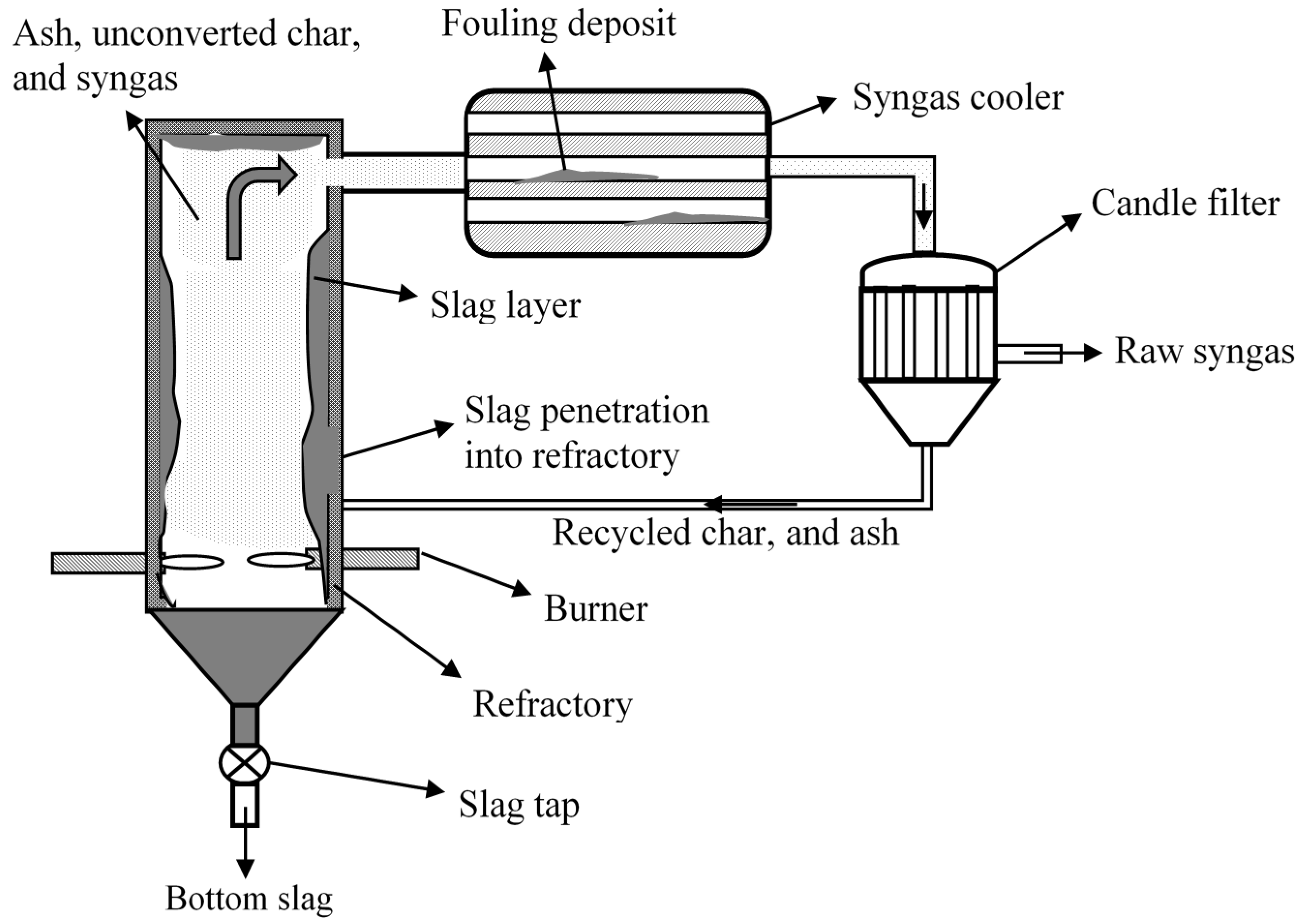
Table 4.
Mineral matter realted outages in major coal-based IGCC power plants (Adapted from Holt [24]).
| Gasifier | Wabash River | Tampa electric | Nuon | ELCOGAS |
|---|---|---|---|---|
| E-Gas | GE | Shell | Prenflo | |
| Refractory wear | Life ~2 years | Life ~2 years (more recently 3 years) | Not significant | Not significant |
| Slag tap blockage | Yes | Yes | No | Yes |
| Corrosion and erosion in circulating slag water | Minor | Yes | Yes | Yes |
| Syngas cooler fouling and corrosion | Yes- can be cleaned with in-situ | Only with convective syngas cooler | Minor | Yes- but not significant |
| Candle filter failure | Yes | Not applicable | No | Yes |
In this kind of gasifiers, slag/ash/char within the gasifier is partially separated by impingement on slag surface or cyclonic action, while fine particles are carried by hot syngas [13,74,75]. The fine char/ash particles carried along with the syngas can result in syngas cooler fouling and thereby reducing the heat transfer efficiency, creating impedance to gas flow, contributing to corrosion and erosion problems—all affecting the overall reliability of the syngas cooler and technology [13,76]. The other major challenge faced in the operation of the entrained flow gasifier is maintaining optimum slagging conditions [7]. A small slag layer on the refractory is desirable as this layer protects the refractory lining and reduces heat loss. However at high temperature and reduced viscosity, the molten slag layer can be very corrosive and can penetrate deeply into the air-cooled refractory lining [77] affecting the stability of the refractory. Besides corrosion, higher operating temperature can also increase the oxygen demand and consequently reduce the efficiency of the gasifier. Operating the entrained flow gasifier at relatively low temperature can increase the slag viscosity, which can affect the discharge of the slag by solidification [78]. Therefore, an optimum condition (1573–1773 K) should be maintained such that slag layer acts as thermal barrier coating for the refractory wall [78] not at the cost of overall efficiency. Other problems include erosion of circulating slag water due to presence of fine sharp solids, and candle filter problems. The erosion issue was handled by avoiding a sharp bend in pipes, while the candle filter problem at Wabash river plant was handled by switching to metallic filters (estimated lifetime of 9000 h) instead of ceramic filters [24]. However, the problem in ELCOGAS seems to have not been resolved as of 2006 [24]. Although reasons like decomposition of nickel from the candle filter and some structural design faults were suggested, the precise reason for the failure of candle filters is not reported in the open literature.
To solve many of the mineral matter related issues including slag mobility, syngas cooler fouling, and slag-refractory interactions and corresponding damages, ash forming mechanisms and ash flow dynamics and gas flow dynamics in the gasifiers have to be understood. This understanding is necessary for designing tools to predict syngas cooler fouling, refractory life, and slag mobility within the gasifier. The following section deals with ash/slag formation.
4.1. Ash/Slag Formation
In the slagging gasifier, inorganic species are either removed as slag or fly ash [72]. Slag is formed when ash particles deposit on the gasifier wall and flow down as highly vitreous product. The remaining ash particles that get entrained out of the gasifier constitute fly ash [72]. The partitioning of inorganic species to fly ash and slag is important from the perspective design and operation of the gasifier. Determining the partitioning of inorganic species to fly ash and slag is complicated due to the heterogeneity of mineral matter.
Ash forming mechanisms during gasification of coal are expected to be similar to those of ash forming mechanisms during combustion. A schematic of mineral transformation in a gasifier is shown in Figure 7. Like combustion, ash particles of wide range of size distribution are likely to be formed due to mechanisms like char fragmentation, ash coalescence, and vaporization and (homogeneous and heterogeneous) condensation of inorganic species [13]. However, only few attempts have been made to determine extent of occurrence of each of those ash forming mechanisms under conditions similar to that of a full-scale entrained flow gasifier. There is a huge knowledge gap on the role of various ash forming mechanisms during gasification at high pressures and temperatures [13]. For example, ash fragmentation from included inorganic particles (inorganic particles embedded in organic matrix) in an entrained flow gasifier is dependent on char morphology. The pressure effects on char morphology and consequently ash fragmentation beyond 2 MPa are not clear [13]. Moreover, the extent of ash coalescence and submicron ash formation occurring in this kind of gasifier at high pressures is also not clear.
Once the ash is formed, it can either report to slag within the gasifier or can get entrained out of the gasifier with the syngas. Mechanisms of transport of ash particles to wall surface are well documented for boiler conditions and is expected to hold well for gasifier as well. For the ash particles to hit the wall surface, it has to have sufficient momentum to deviate from the gas flow field. Mechanisms like inertial impaction, eddy impaction and thermophoresis were shown to provide enough momentum for these particles to hit the wall surface. Role of other mechanisms such as eddy diffusion, molecular diffusion, condensation and chemical reaction in contributing to slag are not very clear especially under turbulent conditions [79,80,81].
When the ash particles come in contact with the wall/slag surface, they can either deposit on the surface or rebound [75,82]. This is because the sticking probability of ash on the slag is also dependent upon the slag and ash properties [75]. For example, particles with substantial carbon (>15–20 mass % [82]) may not enter into the slag layer within the gasifier unless they impact the slag layer at high velocity [75]. This is because the particles with substantial organic matter (>10% by mass) have very high viscosity, low density (or higher buoyancy), and poor wettability in melt phase [83,84], preventing it from deposition inside the gasifier. Despite poor wettability of organic matter in the slag, the amount of combustibles in the industrial gasifier slag (fine and coarse slag) was reported to vary anywhere between 30% and 35% for coarse slag to 60% for fine slag depending upon conditions [85]. One of the possibilities for this observation is that at high operating temperatures, the inorganic melt phase engulfs the organic portion rendering the organic component unreactive. The particles then settle in the slag contributing to unburnt carbon in the slag. Experiments conducted in our laboratory indicated that if all the mineral matter rich fractions contribute to coarse slag, then roughly about 30% of the fractions enclosed in slag is organic matter. Our hypothesis is that fine slag is most likely to form from included mineral matter.
Presence of crystalline inorganic phase in the particle is also important from the perspective of deposition rate. It can be inferred from the work of Shannon et al. [86] that the presence of a substantial amount of crystalline phase in the ash particle increases the viscosity of slag once it gets captured onto the slag. This can affect further deposition. The amount of crystalline phase in the ash particles contributing to slag is expected to be higher for coarser particles due to lower heating rate and shorter residence time at the high temperature zone before hitting the slag layer.
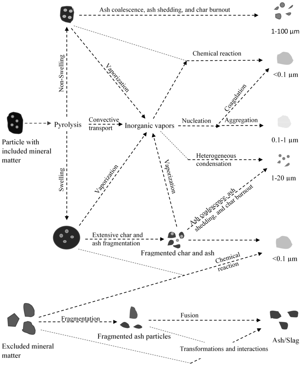
Figure 7.
Mineral matter transformations of pulverized coal particles in an entrained flow gasifier (Modified after Wu et al. [87]).
Figure 7.
Mineral matter transformations of pulverized coal particles in an entrained flow gasifier (Modified after Wu et al. [87]).

Besides wettability and viscosity, the deposition rate of particles from the bulk phase to the slag can be influenced by the particle density, particle size, and swirl [75,88] within the gasification system. Ash particles with higher density are most likely to penetrate into the slag layer as a result of inertial impaction than those of lower density ash particles [88]. This is because higher density particles are subjected to heat dissipation as it impacts slag layer, consequently higher temperature as it hits the slag layer, resulting in increased probability of adhering. The other parameters, such as swirl in the system coupled with high temperatures can influence the deposition by increasing the probability of surface contact of ash particles and by lowering the viscosity of inorganic species. Once the slag is formed, the composition of the slag plays an important role in its mobility within the gasifier. Moreover, the slag composition dictates the refractory degradation [89]. From these perspectives, studying the ash/slag formation is of high importance. The following section discusses the issues relating to the slag mobility within the gasifier.
4.2. Slag Mobility
Continuous discharge of slag is essential for maintaining the smooth operation of the gasifier. Discharge of slag from the gasifier is primarily dependent on slag viscosity, which in turn is dependent on slag composition, oxygen potential of the local atmosphere (ability to transfer oxygen from gas phase to melt phase), and slag temperature [41,78]. It is generally accepted that the slag viscosity has to be maintained below 25 Pa·s at 1773 K for continuous discharge [41,44] irrespective of slag composition. However, the optimum viscosity was suggested to be around 15 Pa·s at 1773 K [44].
To maintain consistent slag flow in the gasifier, operating temperature has to be carefully selected. Operating temperature of the gasifier is usually selected based on ash fusibility characteristics (ash flow temperature) and slag viscosity [78]. As explained in the earlier section, ash fusibility suffers from numerous limitations including the metric being less sensitive to ash composition. This was further confirmed when two coal ashes having same fusibility was shown different slag viscosity-temperature characteristics [90]. The other parameter that is used to determine the suitability of the coal slag is slag viscosity. It is important to recognize that slag viscosity measurement alone takes between 6 to 8 h. This means monitoring the slag viscosity for the coal to be used in the gasifier becomes difficult. The problem becomes more complicated when blended coals are used in the gasifier, with the issue being getting a truly representative sample for slag viscosity and ash fusibility measurement. However to avoid this issue, slag viscosity predictions are more preferred to slag viscosity measurements. Zhu et al. showed that viscosity models can predict viscosity measured in the laboratory [91]. Slag viscosity can be predicted using models like Urbain, Feredey, Watt and Fereday, Kalmanovitch-Urbain and many others [92]. The problem with these models is that it is applicable only for homogeneous slag. Similarly, the viscosity measured in a lab-scale viscometer is also for homogeneous slag. However, in real gasifier, the slag is multilayered varying from completely liquid to completely solid [93]. Application of viscosity models and measurements can bring error for heterogeneous slag in the gasifier. For example, Oh et al. reported that empirical models failed to predict heterogeneous slag viscosity-temperature behavior in the Texaco gasifier. This was due extensive formation dendrite shape spinels that caused rapid increase in viscosity of the slag [94]. It is important to recognize that slags can be classified as glassy slag or crystalline slag. For glassy slags, the viscosity is inversely proportional to temperature and can easily be predicted using models [14]. For crystalline slags, at certain temperature, a small change in temperature can result in large changes in viscosity [14,92]. This temperature is called critical viscosity. The large changes in viscosity are attributed to crystallization. This crystallization of different phases while the slag cools as it approaches the tap makes the slag heterogeneous. Most common phases that crystallize out during cooling are spinels, anorthite, mullite, hematite group and corundum [92]. The kinetics of crystalline behavior is directly linked to degree of polymerization of melt (or viscosity) and is not well understood [95]. Despite limited theoretical understanding, heterogeneous slag viscosity can be predicted using thermodynamic models in conjunction with empirical viscosity models and/or combination of thermodynamic models and tools like HT-XRD [19,39,96,97,98].
Research work on the slag mobility is predominantly focused on measuring viscosity-temperature behavior and critical viscosity of the slag [99,100]. Studies also focused on role of additives on reducing the viscosity of the slag, flow temperature and critical viscosity [44,101]. However, not much effort has been focused on components contributing to the slag. It has to be understood that slag phase composition may not represent the bulk coal ash composition. Wall et al. reported that slag composition is preferentially contributed by the excluded mineral matter based on a pilot scale study [13]. This was further suggested by Yu et al. based on a study of slag in a bench-scale Opposed Multi Burner (OMB) gasifier [102]. This suggests that slag mobility should also be studied based on various density fractions contributing to the slag formation.
4.3. Slag-Refractory Interactions
Reliability and availability of the gasifier is dependent upon ability of refractory lining to withstand elevated temperature (>1773 K), temperature fluctuations, attack of hot corrosive gases, variation in feedstock, cyclic change in oxidizing and reducing conditions, alkali vapor and molten slag [103]. The refractory lining used in gasifiers varies with design. In general, the refractory linings can be classified as air-cooled or water-cooled. The water-cooled refractory lining is also called as a membrane-wall design with stainless steel tubes to carry water/steam covered with a thin layer of Al2O3-SiC refractory [21,104]. When water or steam is used as cooling medium in the furnace shell, a steep temperature gradient is formed between furnace shell and thin-walled refractory layer. This steep gradient causes the molten slag generated during the gasifier operation to solidify and thereby protecting the membrane wall from corrosion and erosion. On the other hand, air cooled refractory lined design is traditionally alumina based, and/or zirconia based refractory for the hot face and has a thick multi layered refractory to reduce heat loss. This kind of design is relatively inexpensive compared to water cooled design. The downside of the design is that the lifetime is extremely short, ranging from anywhere between four and 24 months [14,105]. Studies have identified that the refractory service time as one of the factors limiting the availability of the air cooled refractory walled gasifiers. Keeler reported that the Wabash IGCC plant had 1% of downtime a year due to refractory breach [106]. Replacing refractory lining very often is expensive costing, >1 million dollars in material and lost opportunity combined [105]. To reduce the opportunity cost and to increase the availability, a spare gasifier is always used [24].
Slag-refractory interactions are complex and are dependent on slag composition, refractory composition, and porosity. Slag and refractory composition can be classified as acidic, basic and neutral. An acidic refractory is less resistant to corrosion by basic slag while it is more stable on interaction with acidic slag [107]. For example, corrosion of SiC refractory (typically used for membrane wall gasifiers) was studied in acidic and basic slags. It was observed that corrosion by acidic oxides rich slags on SiC at 1503 K was characterized by localized corrosion by iron silicides, while corrosion by basic oxides rich (predominantly CaO) rich basic slags at 1513 K was characterized by uniform dissolution of refractory [108]. Therefore, matching the refractory composition to slag composition is more important to extend the refractory life [92]. However, the problem is that not all refractories (i.e., acidic refractories) have good properties at high temperatures (>1773 K) [107]. The other problem with matching the refractory composition to the slag composition is that it limits the fuel choices for the gasifier.
To determine the suitable air cooled refractory liners for the slagging gasifiers that operate at very high temperatures, numerous refractory compositions were evaluated including alumina-silicate, high-alumina, chrome-alumina, alumina-magnesia, alumina-chromia-magnesia and SiC [89]. Based on the research and industrial experience only Cr2O3-Al2O3, Cr2O3-MgO and Cr2O3-Al2O3-ZrO2 were found to be suitable to withstand air cooled gasifier environment long enough to be economically feasible [89]. Compositions of chromia refractories used in entrained flow gasifiers are shown in Table 5. Even with advancement in materials, the refractory life is restricted to a maximum of 36 months.
Studies were conducted to determine the causes of corrosion for chromia rich refractories [103,109,110]. Postmortem analysis on spent high chromia from a commercial gasifier indicated that the reaction between FeO in slag and Cr2O3 in refractory forming iron chromium spinel as one of the primary reasons for degradation of the refractory [89]. While the formation of iron chromium spinel prevented the diffusion of FeO into the refractory, it was also suggested to have resulted in chemical spalling [103]. Although Cr2O3 provided corrosion resistance, it did not prevent slag from penetrating. The increased penetration of slag also resulted in structural spalling. Similarly, Guo et al. reported increased concentration of CaO increased the corrosion rate for high chromia refractory [110]. Slag penetration was again cited as the reason for high corrosion rate. Areas of refractory slag attack include pore networks, grain boundaries, and fine matrix regions [111]. One way to reduce penetration is through adding phosphate to the high chrome refractory. Addition of phosphate to high chromia refractory not only reduced porosity but also increased the viscosity of the penetrated slag by interacting with it and consequently reduced spalling [103]. The other approach to reduce slag refractory interaction is to reduce the wettability of refractory by the slag by changing the slag composition or refractory properties. However, not much has been reported in the open literature on changing the wettability of slag or refractory.
Table 5.
Chemical composition and physical properties of commonly used high Chrome Oxide refractories used in air-cooled slagging gasifiers (Adapted from Bennett and Kwong [89]).
| Chemistry (Weight %) | Brick type | ||
|---|---|---|---|
| A | B | C | |
| Cr2O3 | 89.0 | 87.3 | 81.0 |
| Al2O3 | 10.2 | 2.5 | 0.4 |
| ZrO2 | - | 5.2 | Not Reported |
| MgO | 17.0 | ||
| Bulk density (g/cm3) | 4.21 | 4.07 | 3.95 |
| Porosity (vol. %) | 16.7 | 16.5 | 12.0 |
The most common mechanisms through which slag-refractory interactions degrade refractories include chemical dissolution, chemical and physical spalling [89,111]. Chemical dissolution of refractory occurs when the molten slag disrupts the bonding of the refractory structure, allowing the coarse grains to be swept away with the molten slag. At the same time, low viscosity of slag at elevated temperatures allow slags to penetrate through the refractory causing chemical and structural spalling. Chemical spalling occurs when slag-refractory interacts to form an interfacial product with a density change and different thermal expansion coefficient compared to refractory matrix while structural spalling occurs either due penetration of slag into the refractory, and or due thermally induced stress resulting in breakage of the sections of refractory matrix.
4.4. Fouling
As explained in the earlier sections, not all ash formed during gasification forms slag. A portion of ash entrained by syngas deposit in various locations resulting in fouling of the convective sections of the gasifier. Fouling of syngas cooler not only reduce heat transfer efficiency of the syngas cooler but also can contribute to failure of syngas cooler tubes through corrosion and consequently to unscheduled shutdown of the gasifier. Slag quench plugging and syngas cooler tube leaks were the two leading causes for downtime of the Wabash IGCC plant in 2002 [106]. The Polk power station also experienced numerous syngas cooler outages totaling 1500 h of outage between 1999 and 2001 [74]. It is important to note that radiant syngas cooler in Polk power plant worked better than expected, while the problem was mostly concentrated in the convective syngas cooler. Because of the convective syngas cooler problem, GE Energy indicated that their reference plant will have only radiant syngas cooler [112]. This highlights the need to determine the fouling mechanism and ways to reduce the fouling related issues in the convective syngas cooler.
Most of the work so far has been focused on measuring and improving slag mobility within the gasifier while little has been reported in open literature on the nature of the fly ash entrained out of the gasifier and the deposits in the syngas cooler. Brooker studied ash deposits obtained from syngas cooler based on Texaco gasification process [113]. The deposits were found to contain halides, and metal sulfides [113]. Brooker suggested that these halides and sulfides were the result of an “initial fouling layer” on which flyash particles adhere. The presence of the halides in deposits suggested condensation of volatilized species, while iron sulfide played a role in the deposition of siliceous ash particles [113]. Presence of small amount of NaCl in the deposits suggests the presence of chlorine in coal. It was reported that even 0.1% of Cl in coal can result in 200–400 ppm of HCl in gas phase [14]. HCl readily reacts with alkalis, alkali earth metal species and metallic iron to form FeCl2, NaCl and CaCl2. These components not only form initial fouling layer, but also contribute to poisoning of COS-hydrolysis catalyst [14]. Besides chlorides, H2S formed from sulfur species during gasification is not only corrosive to syngas cooler [14,114] but can also contribute to the strengthening the deposit by reacting with very fine iron particles to form pyrrhotite [115].
The other interesting observation with respect to the fouling deposits is the higher concentration of carbon rich particles [13]. Data from a demonstration facility showed that fine particulate stream (60% < 20 µm) entrained out the gasifier was substantially enriched in carbon indicating minimal carbon conversion as the reason for entrainment [13]. These char-ash particles are less likely to get deposited within the gasifier resulting in the entrainment.
Koyama et al. studied the ash deposits obtained from a two-stage entrained-flow gasifier [83]. The deposits were classified into three types: powdery, lump, and molten slag. It was found that some of the deposits were powdery due to presence of carbon rich particles, which prevented sintering of ash. The inorganic phases having low concentration of carbon either partially sintered to form lumps or completely sintered to form molten slag [83]. The authors also found that ash particles started sintering when residual carbon was less than 10% by mass [83]. Influence of residual carbon on the deposition behavior of ash during gasification of Illinois #6 bituminous coal in an atmospheric pressure lab scale entrained flow reactor was studied by Li et al. [82]. The authors showed that at temperatures greater than the ash fusion (or flow) temperature, there is a critical carbon conversion, above which the capture efficiency (ratio of particles deposit on the surface to ratio of particles impacting the surface) of char-ash particles increased dramatically. For Illinois #6 coal, the critical carbon conversion was found to be 88% at 1673 K, while it was found to be 87% at 1773 K. The authors suggested that above critical conversion, the molten inorganic species are sufficiently exposed on the surface for the particle to become sticky [82]. It is not clear to what extent the deposition is caused by organic rich particles (ρHe ≤ 1.3 g/cc) in the feed. Contribution of organic rich and mineral matter rich particles on ash deposition can be studied using density separated coal fractions in lab scale entrained flow gasifier as their flow path in the gasifier is likely to be different. The presence of carbon in the deposit could also be due to engulfment of (fragmented) char particle by melt phase [116]. In such a case, ash particle with some amount of carbon can deposit in the convective regions of the gasifier.
One of the ways to solve fouling related issues is through developing computational models that accurately predict the partitioning and deposition of ash particles in the gasifier. Some progress has been made towards predicting ash deposition and slag thickness in the gasifier [117,118,119,120]. However, their utility is very limited owing to lack of understanding of ash formation mechanisms and ash deposition mechanisms. Determining the partitioning requires particle size distribution of char and ash particles in the gasifier. Particle size distribution of ash and char particles are necessary to calculate stokes number. Stokes number can then be correlated with impaction efficiency (number of particles impacting the wall to the number of the particles in the bulk phase). Due to lack of extensive experimental studies at high pressures and temperatures, the models to predict the particle size distribution of char and ash is far from developed. With respect to correlating stokes number to impaction efficiency, some progress have been made under combustion conditions [79]. However, validity of such correlations especially under turbulent conditions in a gasifier is uncertain. The second step is to determine if the char-ash particle that hits the wall would be deposited on the slag or would be carried out of the gasifier as fly ash. It is known that particle with higher amount of carbonaceous matter is less likely to be captured by the slag [75]. Therefore, a correlation that takes char conversion into account is preferred. However, the traditional methods that characterize ash deposition are based on empirical viscosity models, ash fusion temperature, and based on temperature of critical viscosity (temperature below which the slag transforms from glassy Newtonian phase to crystalline) [121]. The major problem with these methods is that it takes only particle temperature and ash composition into account while neglecting the organic portion of the particle. The other methods to characterize ash deposition include critical carbon conversion, weber number and critical contact angle [122,123]. These are at best a rule-based criteria. It is important to recognize that sticking efficiency in the gasifier is dictated by particle temperature, gas temperature, slag/wall properties, char conversion, particle size distribution, particle velocity, and ash composition. Therefore, to have more reasonable model, sticking efficiency has to take above factors into consideration. In the step towards developing a comprehensive model, efforts have been made to develop an expression that equates Young’s modulus (modulus of elasticity of particle and substrate), particle shape, and particle velocity to coefficient of restitution (ratio of rebounding velocity to the impact velocity of the particle) [124]. Further, a model was also developed to determine critical velocity (below which the particles would settle in the slag) using viscoelastic (theoretical) model [125]. The specialty of the model is that it takes the influence of carbon and ash composition on deposition into account. Although the model was validated with experimental data, more validation of this model is required.
Despite limited understanding of ash forming mechanisms and ash deposition mechanisms, some solutions to fouling were adopted in various IGCC plants. These solutions vary from plant to plant and require adaptive measures. In Puertollano IGCC plant, syngas cooler fouling was due to sticky ash. The problem was overcome through increased syngas velocities through cooler and also through increased recirculation of syngas such that the inlet temperature to the cooler was reduced [126]. In the case of Polk power plant, the fouling in the convective syngas cooler was reduced by reducing the syngas inlet temperature [24]. This was achieved through increasing the heat transfer surface area of the radiant syngas cooler. Other options depending upon the extent of heat recovery from syngas include Texaco quench design (without radiant and convective syngas cooler), downflow fire tube design, or more expensive water tube design.
The Polk power plant also experienced blockage of the convective syngas cooler due to deposits that formed during the initial start-up of the gasifier. Modifications to start-up procedures and the inlet gas flow path to the convective syngas cooler using computational fluid dynamics alleviated the problem [24].
5. Conclusions
In the case of fixed bed gasifiers, bed agglomeration is highly undesirable as it can affect bed permeability and consequently perturb the stable operation of the gasifier. Determining the temperature range of slag formation based on ash fusibility temperature technique is not reliable. Techniques like thermodynamic modeling and viscosity modeling and/or combination of techniques can be used to predict the slag formation and viscosity with reasonable accuracy. A more advanced approach is to develop a computational model that not only tracks the ash/char particle within the gasifier but can also predict the slag formation at various location of gasifier thereby targeting a particular location for temperature reduction in the event of slag formation.
Extensive agglomeration leading to defluidization, and fouling are the major problems in fluidized bed gasifiers. Agglomeration and defluidization in a fluidized bed reactor is affected by mineral matter composition, particle size distribution, and operation related parameters such as operating temperature, steam, O2 stoichiometry, and minimum fluidization velocity. Presence of pyrite, siderite, alkalis, and chlorides is also known to contribute to agglomeration and fouling related issues. Presence of sodium species particularly in low-rank coals contributes to the agglomeration and defluidization through interaction with silica while it forms sticky layer in the convective sections of the gasifiers as a result of condensation. Agglomeration and defluidization can be controlled by careful manipulation of operating conditions (such as temperature, fluidization velocity), blending of coals, water-washing and/or drying, using alternate bed materials, and injecting mineral additives.
The operational challenges in entrained flow gasifiers are largely due to slag tap blockage, refractory degradation, and syngas cooler fouling. Understanding of the process of slagging, fouling and slag viscosity from a mechanistic or phenomenological point of view is very limited. Solving these issues require considerable experimental data, understanding of the extent of various ash forming mechanisms, ash transport mechanisms, partitioning of inorganics into flyash and slag occurring under high pressure and high temperature conditions. The ash depositional studies conducted in the laboratory under gasification conditions are so far not representative of actual conditions prevailing in the gasifier. This means the resulting data is either inadequate or erroneous. Understanding (1) the effect of pressure on ash formation mechanisms; (2) ash transport mechanisms; (3) partitioning of ash to flyash and slag; and (4) development of more reliable computational models appear to be the immediate research needs.
Besides ash and slag formation mechanisms, development of a refractory that remains stable under gasifier conditions for a long period (>36 months) is also another research need. Approaches like reducing the wettability of refractory by altering the properties of the refractory or slag, and reduction of porosity are also worth pursuing. Not much work has been reported in the open literature with respect to altering the wettability characteristic of slag or refractory.
Acknowledgments
The authors would like to acknowledge the financial support provided by US Department of Energy. The authors also thank Nandakumar Krishnamurthy for suggestions provided in improving this document.
Conflicts of Interest
The authors declare no conflict of interest.
References
- Harrison, R.M.; Stedman, J.; Derwent, D. New directions: Why are PM 10 concentrations in Europe not falling? Atmos. Environ. 2008, 42, 603–606. [Google Scholar] [CrossRef]
- Pope, I.C.; Burnett, R.T.; Thun, M.J.; Calle, E.E.; Krewski, D.; Ito, K.; Thurston, G.D. Lung cancer, cardiopulmonary mortality, and long-term exposure to fine particulate air pollution. J. Am. Med. Assoc. 2002, 287, 1132–1141. [Google Scholar] [CrossRef]
- Beer, J.M. Combustion technology developments in power generation in response to environmental challenges. Prog. Energy Combust. Sci. 2000, 26, 301–327. [Google Scholar] [CrossRef]
- Franco, A.; Diaz, A.R. The future challenges for “clean coal technologies”: Joining efficiency increase and pollutant emission control. Energy 2009, 34, 348–354. [Google Scholar] [CrossRef]
- Raask, E. Mineral Impurities in Coal Combustion: Behavior, Problems, and Remedial Measures; Hemisphere Pub. Corp.: Washington, DC, USA, 1985. [Google Scholar]
- Zhang, D.K.; Jackson, P.J.; Vuthaluru, H.B. Low-rank coal and advanced technologies for power generation. In Impact of Mineral Impurities in Solid Fuel Combustion; Gupta, R.P., Wall, T.F., Baxter, L., Eds.; Kluwer Academic Publishers: New York, NY, USA, 1999; pp. 45–64. [Google Scholar]
- Higman, C.; van der Burgt, M. Gasification, 2nd ed.; Gulf Professional Publishing: Burlington, VT, USA, 2008. [Google Scholar]
- Speight, J.G. The Chemistry and Technology of Coal; CRC Press: Boca Raton, FL, USA, 2012. [Google Scholar]
- Wagner, N.J.; Coertzen, M.; Matjie, R.H.; van Dyk, J.C.; John, C.C. Coal gasification. In Applied Coal Petrology; Isabel, S.R., Crelling, J.C., Eds.; Elsevier: Burlington, VT, USA, 2008; pp. 119–144. [Google Scholar]
- Bartels, M.; Lin, W.; Nijenhuis, J.; Kapteijn, F.; van Ommen, J.R. Agglomeration in fluidized beds at high temperatures: Mechanisms, detection and prevention. Prog. Energy Combust. Sci. 2008, 34, 633–666. [Google Scholar] [CrossRef]
- Bryers, R.W. Fireside slagging, fouling, and high-temperature corrosion of heat-transfer surface due to impurities in steam-raising fuels. Prog. Energy Combust. Sci. 1996, 22, 29–120. [Google Scholar] [CrossRef]
- Khadilkar, A.; Rozelle, P.L.; Pisupati, S.V. Models of agglomerate growth in fluidized bed reactors: Critical review, status and applications. Powder Technol. 2014, 264, 216–228. [Google Scholar] [CrossRef]
- Wall, T.F.; Liu, G.-S.; Wu, H.-W.; Roberts, D.G.; Benfell, K.E.; Gupta, S.; Lucas, J.A.; Harris, D.J. The effects of pressure on coal reactions during pulverised coal combustion and gasification. Prog. Energy Combust. Sci. 2002, 28, 405–433. [Google Scholar] [CrossRef]
- Collot, A.G. Matching gasification technologies to coal properties. Int. J. Coal Geol. 2006, 65, 191–212. [Google Scholar] [CrossRef]
- Stubington, J.F.; Sasongko, D. On the heating rate and volatile yield for coal particles injected into fluidised bed combustors. Fuel 1998, 77, 1021–1025. [Google Scholar] [CrossRef]
- Casleton, K.H.; Breault, R.W.; Richards, G.A. System issues and tradeoffs associated with syngas production and combustion. Combust. Sci. Technol. 2008, 180, 1013–1052. [Google Scholar] [CrossRef]
- Soundarrajan, N.; Krishnamurthy, N.; Pisupati, S.V. Characterization of size and density separated fractions of a bituminous coal as a feedstock for entrained slagging gasification. Int. J. Clean Coal Energy 2013, 2, 58–67. [Google Scholar] [CrossRef]
- Van Dyk, J.C.; Waanders, F.B. Manipulation of gasification coal feed in order to increase the ash fusion temperature of the coal enabling the gasifiers to operate at higher temperatures. Fuel 2007, 86, 2728–2735. [Google Scholar] [CrossRef]
- van Dyk, J.C.; Melzer, S.; Sobiecki, A. Mineral matter transformation during sasol-lurgi fixed bed dry bottom gasification—Utilization of HT-XRD and FACTSAGE modelling. Miner. Eng. 2006, 19, 1126–1135. [Google Scholar] [CrossRef]
- Guhl, S. Thermodynamic modelling of the behaviour of mineral matter in the BGL-gasification process. In Proceedings of the GTT (Gesellschaft für Technische Thermochemie und -physik mbH)-Workshop, Herzogenrath, Germany, 11–13 July 2012.
- Sukul, G.; Balaramakrishna, P.V. A review of refractory linings for gasification reactors. J. Aust. Ceram. Soc. 2014, 50, 83–92. [Google Scholar]
- Lee, W.E.; Zhang, S. Melt corrosion of oxide and oxide-carbon refractories. Int. Mater. Rev. 1999, 44, 77–104. [Google Scholar] [CrossRef]
- Skhonde, M.P.; Matjie, R.H.; Bunt, J.R.; Strydom, A.C.; Schobert, H. Sulfur behavior in the sasol-lurgi fixed-bed dry-bottom gasification process. Energy Fuels 2009, 23, 229–235. [Google Scholar] [CrossRef]
- Holt, N. Gasification Technology Status–Technical Update; EPRI Report 1012224; 2006. [Google Scholar]
- Kosminski, A.; Ross, D.P.; Agnew, J.B. Reactions between sodium and silica during gasification of a low-rank coal. Fuel Process. Technol. 2006, 87, 1037–1049. [Google Scholar] [CrossRef]
- Kosminski, A.; Ross, D.P.; Agnew, J.B. Reactions between sodium and kaolin during gasification of a low-rank coal. Fuel Process. Technol. 2006, 87, 1051–1062. [Google Scholar] [CrossRef]
- Hlavac, J. The Technology of Glass and Ceramics; Elsevier Scientific Publishing Company: Amsterdam, The Netherlands, 1983. [Google Scholar]
- Waanders, F.B. The iron mineral changes occurring in lignite coal during gasification. Hyperfine Interact. 2013, 218, 35–40. [Google Scholar] [CrossRef]
- Bryers, R. Factors critically affecting fireside deposits in steam generators. In Impact of Mineral Impurities in Solid Fuel Combustion; Gupta, R.P., Wall, T.F., Baxter, L., Eds.; Kluwer Academic Publishers: New York, USA, 1999; pp. 105–131. [Google Scholar]
- Matjie, R.H.; van Alphen, C.; Pistorius, P.C. Mineralogical characterisation of Secunda gasifier feedstock and coarse ash. Miner. Eng. 2006, 19, 256–261. [Google Scholar] [CrossRef]
- Matjie, R.H.; Li, Z.; Ward, C.R.; French, D. Chemical composition of glass and crystalline phases in coarse coal gasification ash. Fuel 2008, 87, 857–869. [Google Scholar] [CrossRef]
- Matjie, R.H.; Ward, C.R.; Li, Z. Mineralogical transformations in coal feedstocks during carbon conversion, based on packed-bed combustor tests: Part 1. Bulk coal and ash studies. Coal Combust. Gasif. Prod. 2012, 4, 45–54. [Google Scholar]
- Hlatshwayo, T.B.; Matjie, R.H.; Li, Z.; Ward, C.R. Mineralogical characterization of sasol feed coals and corresponding gasification ash constituents. Energy Fuels 2009, 23, 2867–2873. [Google Scholar] [CrossRef]
- ASTM Standard. Standard Test Method for Fusibility of Coal and Coke Ash, Astm International; ASTM Standard: West Conshohocken, PA, USA, 2003; Available online: http://www.astm.org (accessed on 15 June 2014). [CrossRef]
- Huggins, F.E.; Kosmack, D.A.; Huffman, G.P. Correlation between ash-fusion temperatures and ternary equilibrium phase diagrams. Fuel 1981, 60, 577–584. [Google Scholar] [CrossRef]
- Kahraman, H.; Bos, F.; Reifenstein, A.; Coin, C.D.A. Application of a new ash fusion test to theodore coals. Fuel 1998, 77, 1005–1011. [Google Scholar] [CrossRef]
- van Dyk, J.C.; Keyser, M.J. Influence of discard mineral matter on slag-liquid formation and ash melting properties of coal—A FACTSAGEtm simulation study. Fuel 2014, 116, 834–840. [Google Scholar] [CrossRef]
- Slegeir, W.A.; Singletary, J.H.; Kohut, J.F. Application of a microcomputer to the determination of coal ash fusibility characteristics. J. Coal Qual. 1988, 7, 48–54. [Google Scholar]
- van Dyk, J.C.; Waanders, F.B.; Benson, S.A.; Laumb, M.L.; Hack, K. Viscosity predictions of the slag composition of gasified coal, utilizing FACTSAGE equilibrium modelling. Fuel 2009, 88, 67–74. [Google Scholar] [CrossRef]
- Schobert, H.H. Lignites of North America; Elsevier: Amsterdam, The Netherlands, 1995; Volume 23. [Google Scholar]
- Browning, G.J.; Bryant, G.W.; Lucas, J.A.; Wall, T.F. The effects of heterogeneous slag character on viscosity and slag flow in IGCC gasifiers. IFRF Combust. J. 1999, 199901, 1–10. [Google Scholar]
- Gronhovd, G.H.; Harak, A.E.; Fegley, M.M. Some results from slagging, fixed-bed gasification of lignite at pressures to 400 Psig. In Preprints of Papers-American Chemical Society, Division of Fuel Chemistry; American Chemical Society: Philadelphia, PA, USA, 1964. [Google Scholar]
- Schobert, H.H.; Streeter, R.C.; Diehl, E.K. Flow properties of low-rank coal ash slags: Implications for slagging gasification. Fuel 1985, 64, 1611–1617. [Google Scholar] [CrossRef]
- Patterson, J.H.; Hurst, H.J. Ash and slag qualities of Australian bituminous coals for use in slagging gasifiers. Fuel 2000, 79, 1671–1678. [Google Scholar] [CrossRef]
- Basu, P. Combustion and Gasification in Fluidized Beds; CRC Press: Boca Raton, FL, USA, 2006. [Google Scholar]
- Ariyapadi, S.; Shires, P.; Bhargava, M.; Ebbern, D. KBR’s transport gasifier (TRIG)—An advanced gasification technology for SNG production from low-rank coals. In Proceedings of the 25th Annual International Pittsburgh Coal Conference, Pittsburgh, PA, USA, 29 September–2 October 2008.
- Dahlin, R.S.; Peng, W.; Nelson, M.; Vimalchand, P.; Liu, G. Formation and prevention of agglomerated deposits during the gasification of high-sodium lignite. Energy Fuels 2006, 20, 2465–2470. [Google Scholar] [CrossRef]
- Kosminski, A.; Manzoori, A.R. Inorganic Matter Behavior in the Gasification of Southern Australian Coals for Combined Cycle Power Generation Technical Report; Technical Services Department, Electricity Trust of Southern Australia: Adelaide, Australia, 1990. [Google Scholar]
- Lin, C.L.; Peng, T.H.; Wang, W.J. Effect of particle size distribution on agglomeration/defluidization during fluidized bed combustion. Powder Technol. 2011, 207, 290–295. [Google Scholar] [CrossRef]
- Manzoori, A.R.; Agarwal, P.K. The role of inorganic matter in coal in the formation of agglomerates in circulating fluid-bed combustors. Fuel 1993, 72, 1069–1075. [Google Scholar] [CrossRef]
- Vuthaluru, H.B.; Zhang, D.-K.; Linjewile, T.M. Behaviour of inorganic constituents and ash characteristics during fluidised-bed combustion of several Australian low-rank coals. Fuel Process. Technol. 2000, 67, 165–176. [Google Scholar] [CrossRef]
- Kuo, J.-H.; Lin, C.-L.; Wey, M.-Y. Effect of alkali concentrations and operating conditions on agglomeration/defluidization behavior during fluidized bed air gasification. Powder Technol. 2011, 214, 443–446. [Google Scholar] [CrossRef]
- Schafer, H.N.S. Pyrolysis of brown coals. 2. Decomposition of acidic groups on heating in the range 100–900 °C. Fuel 1979, 58, 673–679. [Google Scholar] [CrossRef]
- Murray, J.B. Changes in state of combination of inorganic constituents during carbonization of Victorian brown coal. Fuel 1973, 52, 105–111. [Google Scholar] [CrossRef]
- Kosminski, A.; Ross, D.P.; Agnew, J.B. Transformations of sodium during gasification of low-rank coal. Fuel Process. Technol. 2006, 87, 943–952. [Google Scholar] [CrossRef]
- van Eyk, P.J.; Ashman, P.J.; Alwahabi, Z.T.; Nathan, G.J. The release of water-bound and organic sodium from Loy Yang coal during the combustion of single particles in a flat flame. Combust. Flame 2011, 158, 1181–1192. [Google Scholar] [CrossRef]
- Li, C.-Z. Some recent advances in the understanding of the pyrolysis and gasification behaviour of Victorian brown coal. Fuel 2007, 86, 1664–1683. [Google Scholar] [CrossRef]
- Marinov, V.; Marinov, S.P.; Lazarov, L.; Stefanova, M. Ash agglomeration during fluidized bed gasification of high sulphur content lignites. Fuel Process. Technol. 1992, 31, 181–191. [Google Scholar] [CrossRef]
- Williamson, J.; West, S.S.; Laughlin, M.K. The behaviour of bed material during fluidized bed gasification: The effects of mineral matter interactions. Fuel 1994, 73, 1039–1045. [Google Scholar] [CrossRef]
- Mason, D.M.; Patel, J.G. Chemistry of ash agglomeration in the U-Gas® process. Fuel Process. Technol. 1980, 3, 181–206. [Google Scholar] [CrossRef]
- Khadilkar, A.B.; Rozelle, P.L.; Pisupati, S.V. A study on initiation of ash agglomeration in fluidized bed gasification systems. Fuel 2015, 152, 48–57. [Google Scholar] [CrossRef]
- Anthony, E.J.; Iribarne, A.P.; Iribarne, J.V.; Talbot, R.; Jia, L.; Granatstein, D.L. Fouling in a 160 MWe FBC boiler firing coal and petroleum coke. Fuel 2001, 80, 1009–1014. [Google Scholar] [CrossRef]
- Kreutzkam, B.; Wieland, C.; Spliethoff, H. Improved numerical prediction of ash formation and deposition using a novel developed char fragmentation model. Fuel 2012, 98, 103–110. [Google Scholar] [CrossRef]
- Vuthaluru, H.B.; Zhang, D.-K. Control methods for remediation of ash-related problems in fluidised-bed combustors. Fuel Process. Technol. 1999, 60, 145–156. [Google Scholar] [CrossRef]
- Butler, C.J.; Green, A.M.; Chaffee, A.L. The fate of trace elements during MTE and HTD dewatering of latrobe valley brown coals. Coal Prep. 2007, 27, 210–229. [Google Scholar] [CrossRef]
- Artanto, Y.; Chaffee, A.L. Dewatering low rank coals by mechanical thermal expression (MTE) and its influence on organic carbon and inorganic removal. Coal Prep. 2005, 25, 251–267. [Google Scholar] [CrossRef]
- Vuthaluru, H.B.; Zhang, D.K. Effect of coal blending on particle agglomeration and defluidisation during spouted-bed combustion of low-rank coals. Fuel Process. Technol. 2001, 70, 41–51. [Google Scholar] [CrossRef]
- Tillman, D.A.; Duong, D.N.B.; Harding, N.S. Chapter 3—Blending coal on coal. In Solid Fuel Blending; Butterworth-Heinemann: Boston, MA, USA, 2012; pp. 71–123. [Google Scholar]
- Kyi, S.; Chadwick, B.L. Screening of potential mineral additives for use as fouling preventatives in Victorian brown coal combustion. Fuel 1999, 78, 845–855. [Google Scholar] [CrossRef]
- Vuthaluru, H.B.; Zhang, D.K. Effect of Ca- and Mg-bearing minerals on particle agglomeration defluidisation during fluidised-bed combustion of a south Australian lignite. Fuel Process. Technol. 2001, 69, 13–27. [Google Scholar] [CrossRef]
- McCullough, D.P.; van Eyk, P.J.; Ashman, P.J.; Mullinger, P.J. Investigation of agglomeration and defluidization during spouted-bed gasification of high-sodium, high-sulfur south australian lignite. Energy Fuels 2011, 25, 2772–2781. [Google Scholar] [CrossRef]
- Wabash River Coal Gasification Repowering Project: A DOE Assessment; U.S. Department of Energy: Washington, DC, USA, 2002.
- U.S. Department of Energy. Gasifier Database. Available online: http://www.netl.doe.gov/research/Coal/energy-systems/gasification /gasifipedia/ (accessed on 7 July 2015).
- Tampa Electric Polk Power Station Integrated Gasification Combined Cycle Project: Final Technical Report; U.S. Department of Energy: Washington, DC, USA, 2002.
- Shannon, G.N.; Rozelle, P.L.; Pisupati, Sarma V.; Sridhar, S. Conditions for entrainment into a FeOx containing slag for a carbon-containing particle in an entrained coal gasifier. Fuel Process. Technol. 2008, 89, 1379–1385. [Google Scholar] [CrossRef]
- Wabash River Coal Gasification Repowering Project: Final Technical Report; U.S. Department of Energy: Washington, DC, USA, 2000.
- Mondal, P.; Dang, G.S.; Garg, M.O. Syngas production through gasification and cleanup for downstream applications—Recent developments. Fuel Process. Technol. 2011, 92, 1395–1410. [Google Scholar] [CrossRef]
- Wang, P.; Massoudi, M. Slag behavior in gasifiers. Part I: Influence of coal properties and gasification conditions. Energies 2013, 6, 784–806. [Google Scholar]
- Baxter, L.L.; DeSollar, R.W. A mechanistic description of ash deposition during pulverized coal combustion: Predictions compared with observations. Fuel 1993, 72, 1411–1418. [Google Scholar] [CrossRef]
- Wall, T.F. Mineral matter transformations and ash deposition in pulverised coal combustion. Symp. (Int.) Combust. 1992, 24, 1119–1126. [Google Scholar] [CrossRef]
- Mueller, C.; Selenius, M.; Theis, M.; Skrifvars, B.-J.; Backman, R.; Hupa, M.; Tran, H. Deposition behaviour of molten alkali-rich fly ashes—Development of a submodel for CFD applications. Proc. Combust. Inst. 2005, 30, 2991–2998. [Google Scholar] [CrossRef]
- Li, S.; Wu, Y.; Whitty, K.J. Ash deposition behavior during char—Slag transition under simulated gasification conditions. Energy Fuels 2010, 24, 1868–1876. [Google Scholar] [CrossRef]
- Koyama, S.; Morimoto, T.; Ueda, A.; Matsuoka, H. A microscopic study of ash deposits in a two-stage entrained-bed coal gasifier. Fuel 1996, 75, 459–465. [Google Scholar] [CrossRef]
- Khanna, S.K.; Wu, C.; Sahajwalla, V. Estimation of critical carbon particle engulfment velocity in metallurgical melts. High Temp. Mater. Process. 1998, 17, 193–202. [Google Scholar] [CrossRef]
- Wu, T.; Gong, M.; Lester, E.; Wang, F.; Zhou, Z.; Yu, Z. Characterisation of residual carbon from entrained-bed coal water slurry gasifiers. Fuel 2007, 86, 972–982. [Google Scholar] [CrossRef]
- Shannon, G.N.; Matsuura, H.; Rozelle, P.; Fruehan, R.J.; Pisupati, S.; Sridhar, S. Effect of size and density on the thermodynamic predictions of coal particle phase formation during coal gasification. Fuel Process. Technol. 2009, 90, 1114–1121. [Google Scholar] [CrossRef]
- Wu, H.; Bryant, G.; Wall, T. The effect of pressure on ash formation during pulverized coal combustion. Energy Fuels 2000, 14, 745–750. [Google Scholar] [CrossRef]
- Huang, L.Y.; Norman, J.S.; Pourkashanian, M.; Williams, A. Prediction of ash deposition on superheater tubes from pulverized coal combustion. Fuel 1996, 75, 271–279. [Google Scholar] [CrossRef]
- Bennett, J.; Kwong, K.-S. Failure mechanisms in high chrome oxide gasifier refractories. Metall. Mater. Trans. A 2011, 42, 888–904. [Google Scholar] [CrossRef]
- Trapp, B.; Moock, N.; Denton, D. Coal gasification: Ready for prime time. Available online: http://www.clean-energy.us/projects/eastman_power_magazine.htm (accessed on 30 December 2014).
- Zhu, J.; Kaneko, T.K.; Mu, H.; Bennett, J.P.; Sridhar, S. Effects of measurement materials and oxygen partial pressure on the viscosity of synthetic eastern and western united states coal slags. Energy Fuels 2012, 26, 4465–4474. [Google Scholar] [CrossRef]
- Kinaev, N. A Review of Mineral Matter Issues in Coal Gasification; Cooperative Research Center for Coal in Sustainable Development: Pullenvale, QLD, Australia, 2006. [Google Scholar]
- Bockelie, M.; Denison, M.; Chen, Z.; Linjewile, T.; Senior, C.; Sarofim, A.; Holt, N. CFD Modelling of Entrained Flow Gasifiers. In Proceedings the Gasification Technologies Conference, San Francisco, CA, USA, 27–30 October 2002.
- Oh, M.S.; Brooker, D.D.; de Paz, E.F.; Brady, J.J.; Decker, T.R. Effect of crystalline phase formation on coal slag viscosity. Fuel Process. Technol. 1995, 44, 191–199. [Google Scholar] [CrossRef]
- Sridhar, S.; Rozzelle, P.; Morreale, B.; Alman, D. Materials challenges for advanced combustion and gasification fossil energy systems. Metall. Mater. Trans. A 2011, 42, 871–877. [Google Scholar] [CrossRef]
- Yuan, H.; Liang, Q.; Gong, X. Crystallization of coal ash slags at high temperatures and effects on the viscosity. Energy Fuels 2012, 26, 3717–3722. [Google Scholar] [CrossRef]
- Kondratiev, A.; Jak, E. Predicting coal ash slag flow characteristics (viscosity model for the Al2O3-CaO-FeO-SiO2 system). Fuel 2001, 80, 1989–2000. [Google Scholar] [CrossRef]
- Song, W.; Sun, Y.; Wu, Y.; Zhu, Z.; Koyama, S. Measurement and simulation of flow properties of coal ash slag in coal gasification. AIChE J. 2011, 57, 801–818. [Google Scholar] [CrossRef]
- Song, W.; Tang, L.; Zhu, X.; Wu, Y.; Rong, Y.; Zhu, Z.; Koyama, S. Fusibility and flow properties of coal ash and slag. Fuel 2009, 88, 297–304. [Google Scholar] [CrossRef]
- Li, X.; Li, G.; Cao, Z.; Xu, S. Research on flow characteristics of slag film in a slag tapping gasifier. Energy Fuels 2010, 24, 5109–5115. [Google Scholar] [CrossRef]
- Kong, L.; Bai, J.; Bai, Z.; Guo, Z.; Li, W. Effects of CaCO3 on slag flow properties at high temperatures. Fuel 2013, 109, 76–85. [Google Scholar] [CrossRef]
- Yu, G.; Zhu, Q.; Chi, G.; Guo, Q.; Zhou, Z. Study on slag composition and flow property in a bench-scale OMB gasifier. Fuel Process. Technol. 2012, 104, 136–143. [Google Scholar] [CrossRef]
- Kwong, K.; Petty, A.; Bennett, J.; Krabbe, R.; Thomas, H. Wear mechanisms of chromia refractories in slagging gasifiers. Int. J. Appl. Ceram. Technol. 2007, 4, 503–513. [Google Scholar] [CrossRef]
- Bennett, J.P. Refractory liner materials used in slagging gasifiers. Refractories Appl. News 2004, 9, 20–24. [Google Scholar]
- Dogan, C.P.; Kwong, K.S.; Benett, J.P.; Chinn, R.E.; Dahlin, C.L. New develpments in gasifier refractories. In Proceedings of the Gasification Technologies Conference, San Francisco, CA, USA, 27–30 October 2002.
- Keeler, C.G. Operating experience at the Wabash river repowering project. In Proceedings of the Gasification Technologies Conference, San Francisco, CA, USA, 27–30 October 2003.
- Kwong, K.; Bennett, J.; Nakano, J. Gasifier refractories, coal slags, and their interaction. In Proceedings of the 9th International Conference on Molten Slags, Fluxes and Salts, Beijing, China, 27–30 May 2012.
- Strobel, T.M.; Hurley, J.P. Coal-ash corrosion of monolithic silicon carbide-based refractories. Fuel Process. Technol. 1995, 44, 201–211. [Google Scholar] [CrossRef]
- Kim, H.B.; Oh, M.S. Changes in microstructure of a high chromia refractory due to interaction with infiltrating coal slag in a slagging gasifier environment. Ceram. Int. 2008, 34, 2107–2116. [Google Scholar] [CrossRef]
- Guo, Z.-Q.; Han, B.-Q.; Dong, H. Effect of coal slag on the wear rate and microstructure of the ZrO2-bearing chromia refractories. Ceram. Int. 1997, 23, 489–496. [Google Scholar] [CrossRef]
- Nakano, J.; Sridhar, S.; Bennett, J.; Kwong, K.-S.; Moss, T. Interactions of refractory materials with molten gasifier slags. Int. J. Hydrog. Energy 2011, 36, 4595–4604. [Google Scholar] [CrossRef]
- Atwell, M. GE/Bechtel alliance IGCC reference plant update. In Proceedings of the Gasification Technologies Conference, San Francisco, CA, USA, 14–17 October 2007.
- Brooker, D. Chemistry of deposit formation in a coal gasification syngas cooler. Fuel 1993, 72, 665–670. [Google Scholar] [CrossRef]
- Bakker, W. High temperature corrosion in gasifiers. Mater. Res. 2004, 7, 53–59. [Google Scholar] [CrossRef]
- Brooker, D.; Oh, M.S. Iron sulfide deposition during coal gasification. Fuel Process. Technol. 1995, 44, 181–190. [Google Scholar] [CrossRef]
- Vassilev, S.V.; Vassileva, C.G.; Baxter, D.; Andersen, L.K. A new approach for the combined chemical and mineral classification of the inorganic matter in coal. 2. Potential applications of the classification systems. Fuel 2009, 88, 246–254. [Google Scholar] [CrossRef]
- Ai, W.; Kuhlman, J.M. Simulation of coal ash particle deposition experiments. Energy Fuels 2011, 25, 708–718. [Google Scholar] [CrossRef]
- Slezak, A.; Kuhlman, J.M.; Shadle, L.J.; Spenik, J.; Shi, S. CFD simulation of entrained-flow coal gasification: Coal particle density/sizefraction effects. Powder Technol. 2010, 203, 98–108. [Google Scholar] [CrossRef]
- Lee, H.-H.; Lee, J.-C.; Joo, Y.-J.; Oh, M.; Lee, C.-H. Dynamic modeling of shell entrained flow gasifier in an integrated gasification combined cycle process. Appl. Energy 2014, 131, 425–440. [Google Scholar] [CrossRef]
- Casella, F.; Colonna, P. Dynamic modeling of IGCC power plants. Appl. Therm. Eng. 2012, 35, 91–111. [Google Scholar] [CrossRef]
- Wieland, C.; Kreutzkam, B.; Balan, G.; Spliethoff, H. Evaluation, comparison and validation of deposition criteria for numerical simulation of slagging. Appl. Energy 2012, 93, 184–192. [Google Scholar] [CrossRef]
- Chen, L.; Yong, S.Z.; Ghoniem, A.F. Modeling the slag behavior in three dimensional CFD simulation of a vertically-oriented oxy-coal combustor. Fuel Process. Technol. 2013, 112, 106–117. [Google Scholar] [CrossRef]
- Gibson, L.; Soundarrajan, N.; Spenik, J.; Ma, J.; Shadle, L.; Pisupati, S.V. Application of particle population model to determine the contribution to slag, flyash, and syngas in entrained flow gasification from particle size distribution. Energy Fuels 2013, 27, 7681–7695. [Google Scholar] [CrossRef]
- Gibson, L.M.; Gopalan, B.; Pisupati, S.V.; Shadle, L.J. Image analysis measurements of particle coefficient of restitution for coal gasification applications. Powder Technol. 2013, 247, 30–43. [Google Scholar] [CrossRef]
- Gibson, L.M.; Shadle, L.J.; Pisupati, S.V. Determination of sticking probability based on the critical velocity derived from a visco-elastoplastic model to characterize ash deposition in an entrained flow gasifier. Energy Fuels 2004, 28, 5307–5317. [Google Scholar] [CrossRef]
- Garcia Pena, F. Operating experience and current status of Puertollano IGCC power plant. In Proceedings of the 1st International Freiberg Conference on IGCC & XtL Technologies, Freiberg, Germany, 15–18 June 2005.
© 2015 by the authors; licensee MDPI, Basel, Switzerland. This article is an open access article distributed under the terms and conditions of the Creative Commons Attribution license (http://creativecommons.org/licenses/by/4.0/).