2.3.1. Design of the Internal Combustion Engine (ICE)
According to the design specifications shown in
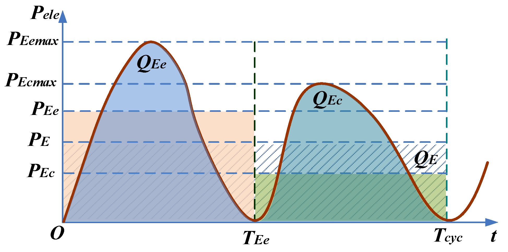
Table 1 and the energy flow diagram shown in
Figure 3, the effective mechanical output power of the ICE can be determined by:
where
PE is the effective electric output power, and η
g is the generating efficiency of LEM.
The equivalent crankshaft speed can be calculated as:
where
Nstrokes is the number of strokes, and
fm is the motion frequency.
The mean velocity of the free-piston is:
where
S is the stroke length.
The discharge capacity of the ICE can be calculated by:
where
Ncylinder is the number of cylinders,
D is the cylinder bore,
S is the stroke length,
pme is the mean effective in-cylinder pressure which can also be expressed as:
The power per liter of the ICE is:
The ICE in this paper is a two-stroke engine with single cylinder, thus
Nstrokes = 2 and
Ncylinder = 1. As shown in
Table 2, the average mechanical power
Pme = 26.6 kW. The motion frequency is expected to be 35 Hz. The mean velocity of the piston is less than 8.5 m/s. The mean effective in-cylinder pressure of a motorcycle gasoline engine lies in the range of 0.78 MPa to 1.2 MPa in general. Considering that the velocity of the free-piston is less than that of the conventional engine, the effective in-cylinder pressure of the free-piston engine is therefore lower. As a result it is designed to be 0.78 MPa. Afterwards, we can determine that the equivalent crankshaft speed
ncrank = 2100 rpm, the stroke length
S = 120 mm, the cylinder bore
D = 102 mm, and the ratio of stroke length to bore ρ
SD = 1.18. The combustion clearance space
Sc is generally about 5 to 10 percent of the stroke length, i.e., 6–12 mm. In this work, it is designed to be 10 mm. The discharge capacity is 980 cc. The power per liter
PL = 27.14 kW/L.
According to
Figure 3, it is easy to know that the combustion heat released in each cycle can be described as:
where
Hu is the calorific value of fuel, χ
B is the mass fraction burned in the combustion process and it can be described with the Weiber function as below [
46,
47]:
where
t0 is the ignition beginning time and
td is the combustion duration,
t is the time variable,
a0 is an experimental constant and
b0 is the combustion quality factor.
Thus, from (3), (16) and (17) the injected fuel mass of each cycle can be determined as:
Another key operational parameter is the initial pressure of the ICE cylinder, which is dependent on the injection mode. In this work, we employ a premixing injection mode without pressure boost. Therefore, the initial pressure of the ICE is almost the same to the standard atmospheric pressure.
Table 4 lists the specifications of the ICE obtained above.
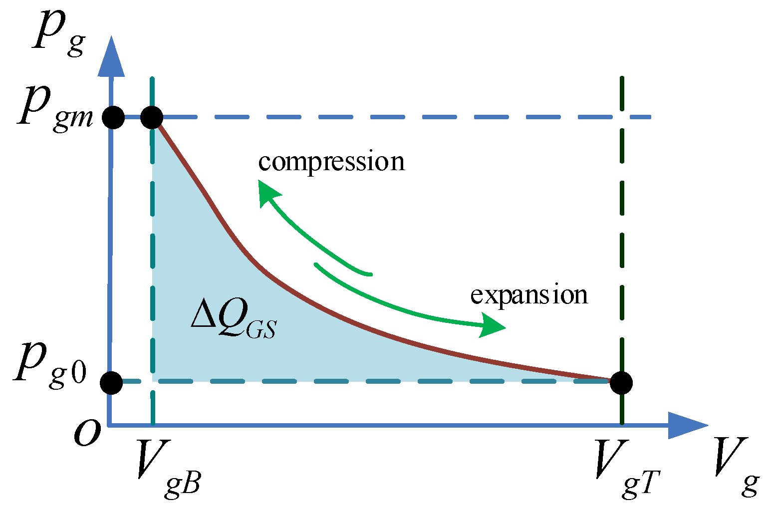
2.3.2. Design of the Gas Spring (GS)
The crucial geometric dimensions of the GS can also be determined based on the energy conversion relationship.
Figure 7 shows the P-V diagram of the GS. At steady operation, during the expansion-generating stroke of the ICE, the GS is compressed and part of the combustion released energy Δ
QGS is stored in GS as shown in
Figure 7.
The energy stored in GS can be calculated as:
where
pmeg,
Dg,
Sg are the mean effective pressure, cylinder bore, stroke length of the GS, respectively,
pg and
pg0 are the instantaneous and initial pressure in the GS cylinder,
VgT and
VgB are the instantaneous volume when the piston is respectively at its TDC and BDC positions, and
Vg is the instantaneous working volume of the GS cylinder.
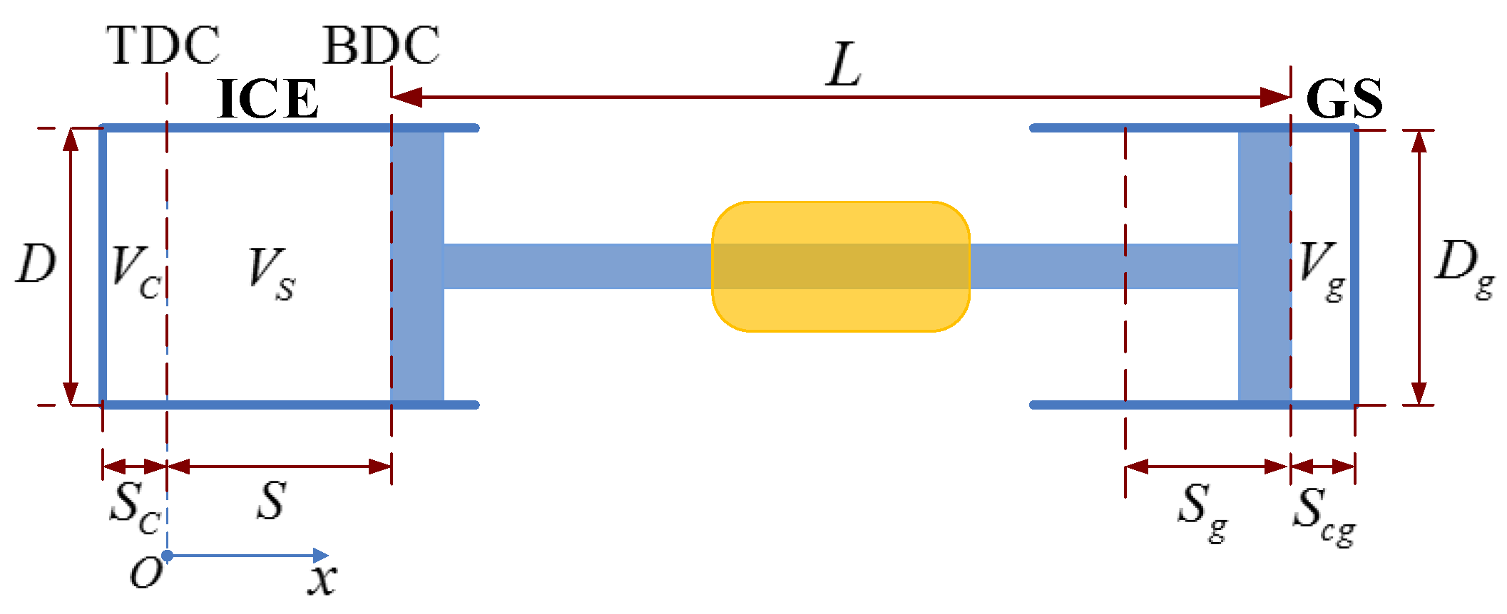
According to
Figure 6, the stroke length of the GS equals to that of ICE, i.e.,
Sg =
S = 120 mm. Considering the convenience of modeling analysis and manufacturing, the cylinder bore of GS is designed the same with that of ICE, i.e.,
Dg =
D = 102 mm. Therefore, the mean effective pressure of GS
pmeg can be calculated to be 0.2 MPa according to (19).
The pressure in the bounce chamber of the GS is significant for the compression-generating efficiency. Neglecting the stiffness regulation process and heat transferring of the GS, during compression-generating stroke, the pressure in the GS chamber can be described as:
where
Rgs is the gas constant,
Cvg is the constant-volume specific heat, γ is the polytrophic exponent.
Finally, the GS pressure can be obtained as:
This states that the pressure profile of the GS is mainly determined by the initial pressure and the instantaneous volume of the GS, which is highly depended on the piston velocity. The initial pressure of the GS can be obtained from (2), (19) and (22) as below:
where
VgT and
VgB are the instantaneous volume of the GS chamber when the piston is respectively at the TDC and BDC positions. Because the geometric dimensions of the GS have been confirmed,
VgT and
VgB are easy to be determined. Therefore, it is easy to know that the initial GS pressure
pg0 = 0.22681 MPa. The GS specifications obtained above are listed in
Table 5.
2.3.3. Design of the Linear Electrical Machine (LEM)
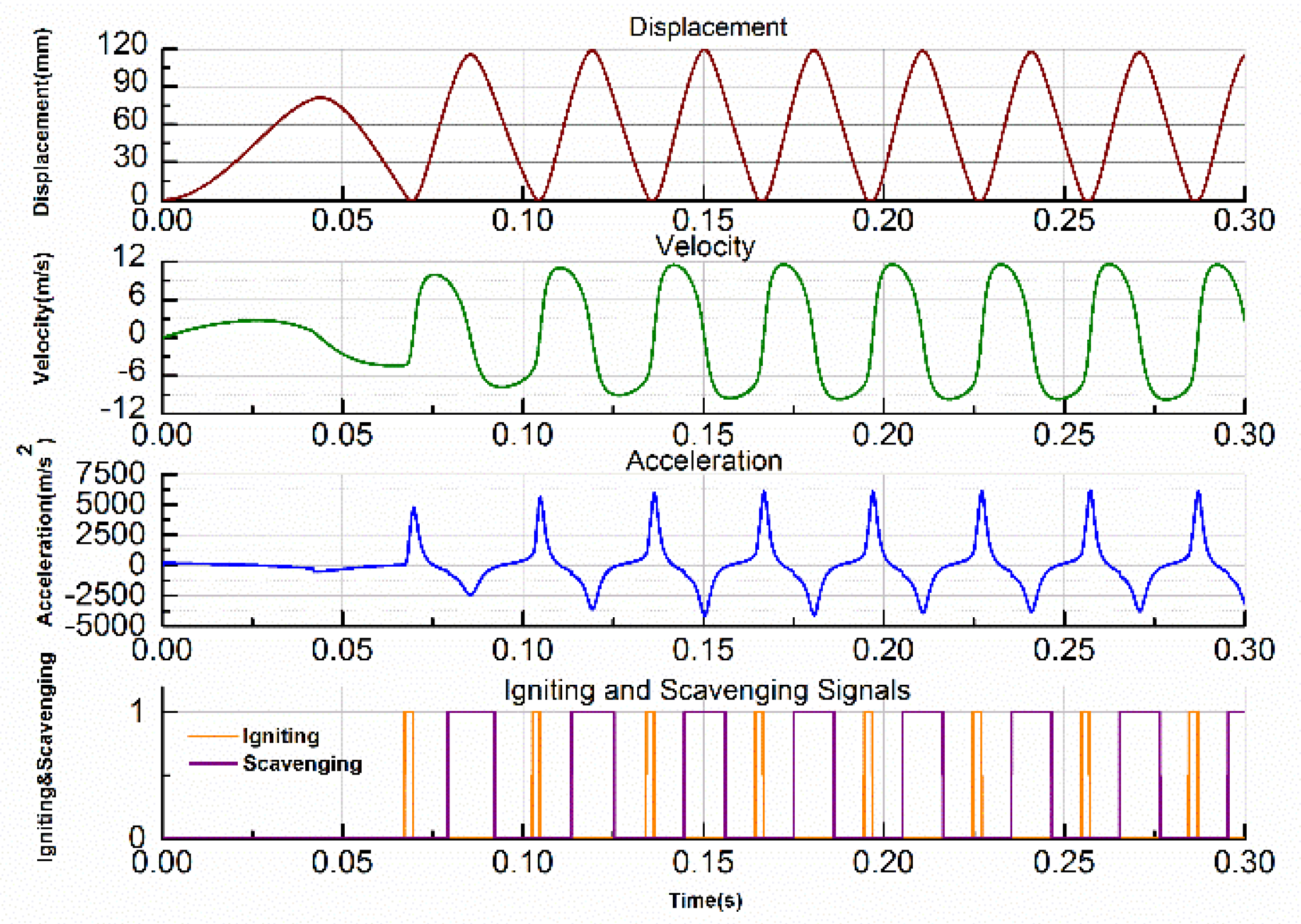
The LEM works as a motor to start the FPLG. Assuming that there is no burned gas in the cylinder and both the intake and exhaust valves are closed at the end of the previous stopping process. As the premixed combustion mode is adopted, the intake valve is opened (IVO) and the premixed flammable gas is sprayed into the ICE cylinder at the beginning of the starting process.
As shown in
Figure 8, in the starting phase, the piston is driven from TDC to BDC by the electric motoring force, meanwhile the GS is compressed. When the piston arrives the critical starting position
xsta, the LEM is switched to generating mode and the piston begins to slow down. When it arrives at the scavenging position
xsca, the intake valve is closed (IVC). The piston is pushed towards TDC mainly by the GS rebounding force. When it reaches the igniting position
xign, the first ignition starts (IGS). After that, the piston is driven by the combustion expansion force and moves towards BDC. When it reaches the scavenging position
xsca and the injecting position
xinj in sequence, the exhaust and intake valves are opened respectively (EVO and IVO).
If the piston can reach the BDC position, it means that it satisfies the necessary conditions of the next ignition. When it continues moving to the positions
xinj and
xsca from BDC to TDC, the exhaust and intake valves are closed (EVC and IVC) in order. If the piston can reach the position
xign and the ICE is ignited, then the system is started successfully and it turns into steady operation. Otherwise, it needs to be started again by repeating the operations described above. According to the descriptions above, the key of successful starting is that the piston can be driven to the specific position
xsta with sufficient motoring force. It means that the motoring force must be larger than a certain value which can be determined from:
where
FEm is the effective motoring force at starting process, Δ
Wp and Δ
Wpg represent the work of the ICE and GS on the piston, respectively, Δ
Wf indicates the friction loss, Δ
Wk is the kinetic energy of the piston when it arrives the specific starting position
xsta.
There exists a minimum motoring-starting force, which can be derived from (24) as follows:
where
xsta is the scavenging position,
VGsta and
Vsta are the volumes of the GS and ICE chambers when the piston is at the
xsta position,
V0 is the initial volume of the ICE cylinder,
vs is the essential starting velocity when the piston arrives the position
xsta,
Bv is the friction coefficient and
M is the total moving mass.
The mass of the LEM mover should be taken into consideration. The FPLG can be simply regarded as a forced vibration system with a natural frequency. Therefore there is also certain constraint among the motion frequency, the moving mass and the equivalent compression ratio, which can be described as:
The system equivalent stiffness
Keq can be calculated by:
where
x0 is the equilibrium position, ε
0 is the objective compression ratio, ε
p and ε
g are the compression ratios of the ICE and GS when the piston is at the equilibrium position, and:
From (26) and (27), it is concluded that the system equivalent stiffness Keq is highly related to the compression ratio, the initial ICE in-cylinder pressure p0 and the initial GS pressure pg0. Under a certain Keq, the total moving mass should be optimized for different motion frequencies.
Figure 9 shows the relationship between the equivalent system stiffness and initial GS pressure, when the geometric dimensions of the ICE are designed as shown above and its initial pressure
p0 = 0.125 MPa. The corresponding compression ratio is 13:1. It is obvious that the equivalent system stiffness is almost proportional to the initial GS pressure
pg0.
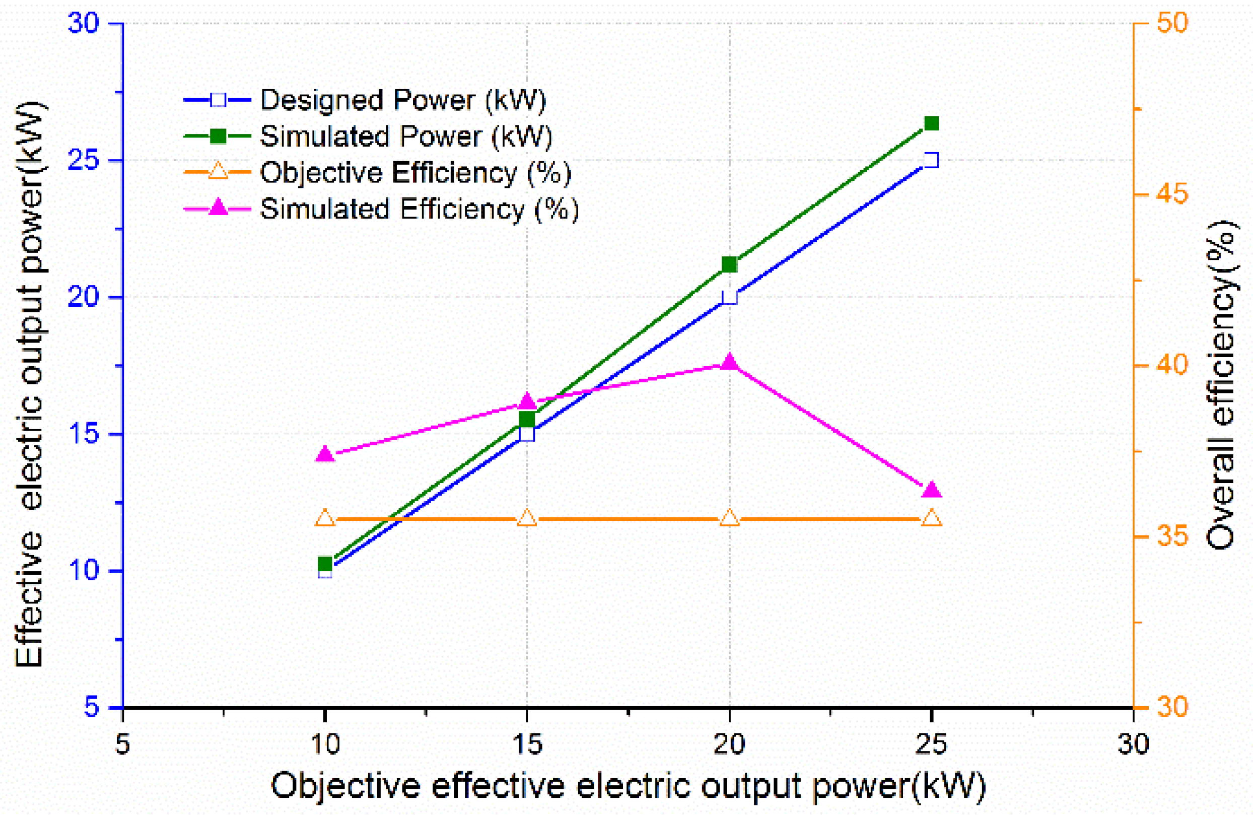
Figure 10 depicts that the key operational parameters, like the initial GS pressure, motion frequency and equivalent system stiffness, increase almost linearly with the increasing of the objective output power. Meanwhile, the moving mass must be reduced accordingly.
As the motion frequency is 35 Hz, from (26)–(31), we can calculate that the moving mass is 12 kg theoretically, which is the total mass including the LEM mover, the ICE piston, the GS piston and the connecting devices. Considering this, the mass of the LEM mover must be designed less than 12 kg and the lighter the better. The equilibrium position is x0 = 44.5 mm. The equivalent system stiffness is 580,240 kg/s2. The critical starting position xsta is defined at 85 mm, and the essential starting force is about 2853 N.
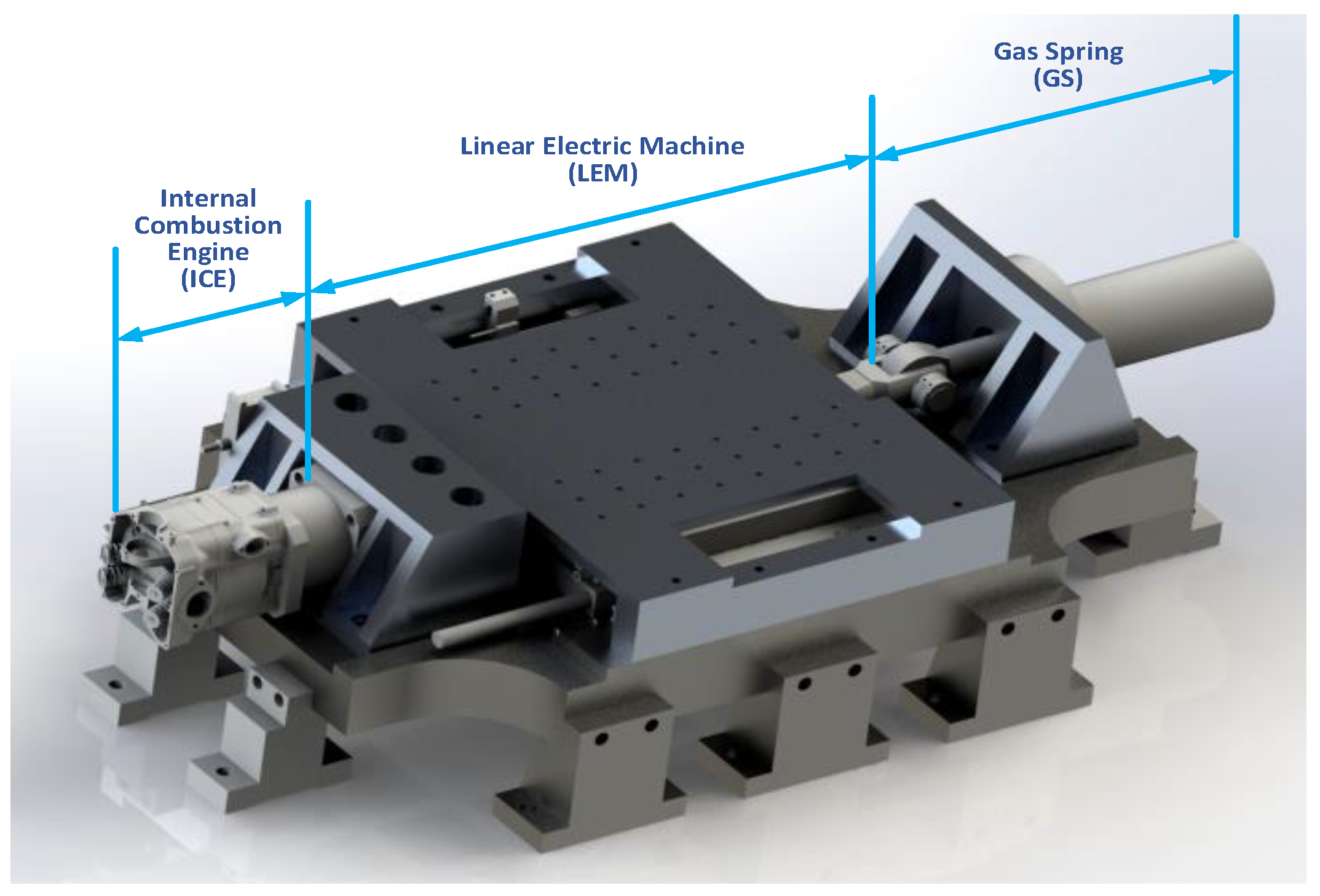
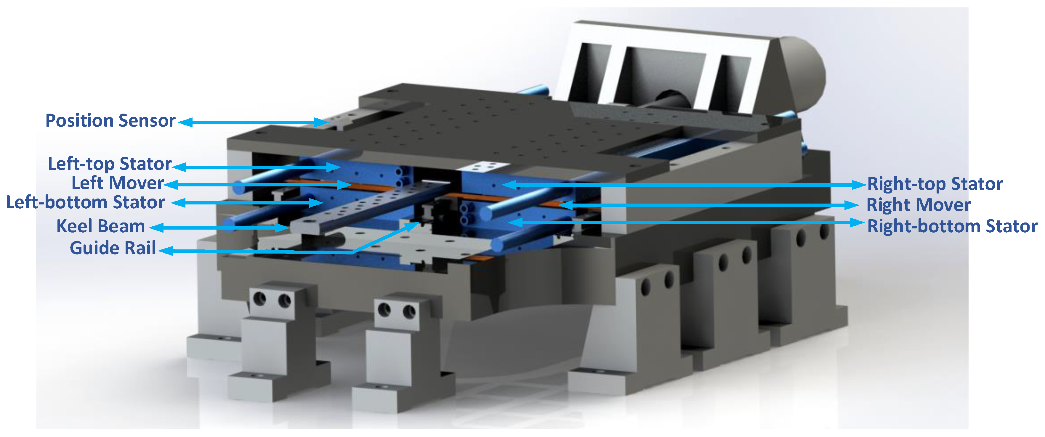
The LEM in this work is specially designed, as shown in
Figure 11. In order to improve the electric power production capability, two linear electric machine units are assembled symmetrically. Each LEM unit is a 3-phase 21-pole/18-slot flat double-sided moving-magnet Permanent Magnet Synchronous Linear Machine (PMSLM) with Halbach magnet arrays, as shown in
Figure 12. The left and right movers are connected with a middle keel beam, which is supported by a slide guide rail. Two guide rails are also assembled symmetrically on both sides of the mover plate. The mass of the LEM mover is less than 8.5 kg, and it can be further reduced by utilizing the special materials like the carbon fiber. The force constant is 150 N/A. And the line-to-line back electromotive force (EMF) coefficient is 87 V/ms
−1.
The LEM is a notable component for the free-piston linear generator (FPLG) system. It is directly integrated between the internal combustion chamber and a rebounding device like a gas spring. In regards of the HEVs applications, the linear electrical generator is a core device that converts the mechanical energy of the piston-rod into electrical energy, and directly outputs to the load. Its performances has significant effects on the overall system performances. Besides, the electromagnetic force of the linear electrical generator determines the piston motion. The dynamic behavior of the piston-rod is highly dependent upon the mechanical-electrical response time of the linear electric generator. In addition, the LEM plays an important role in FPLG system, which requires that the LEM can not only run as a starting motor, but also a generator. Therefore, design an appropriate electrical generator solution specifically for FPLG system makes great sense [
15,
43,
48].
The detailed LEM design process is not the key subject of this paper, therefore we simply provide the major structural parameters and performance specifications, which are listed in
Table 6, where η
g is the generating efficiency,
Ls is the winding inductance,
Rs is the phase winding resistance,
Ld and
Lq are respectively d-axis and q-axis inductance, ψ
f is the PM flux,
N is the number of winding turns per phase, τ
p is the pole pitch,
ge is the effective air gap length, τ and
hm are the width and thickness of PM,
Hc is the coercive force of PM,
Bm is the maximum air gap magnetic density,
H is the stator width.


 ,
, 


