
A Decentralized Control Method for Distributed Generations in an Islanded DC Microgrid Considering Voltage Drop Compensation and Durable State of Charge


Abstract
:1. Introduction
2. Control Scheme of Energy Storage System and Distributed Generation
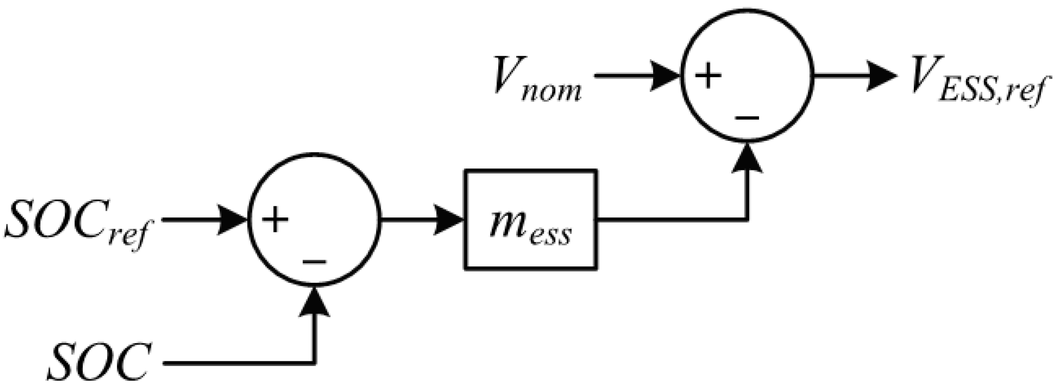
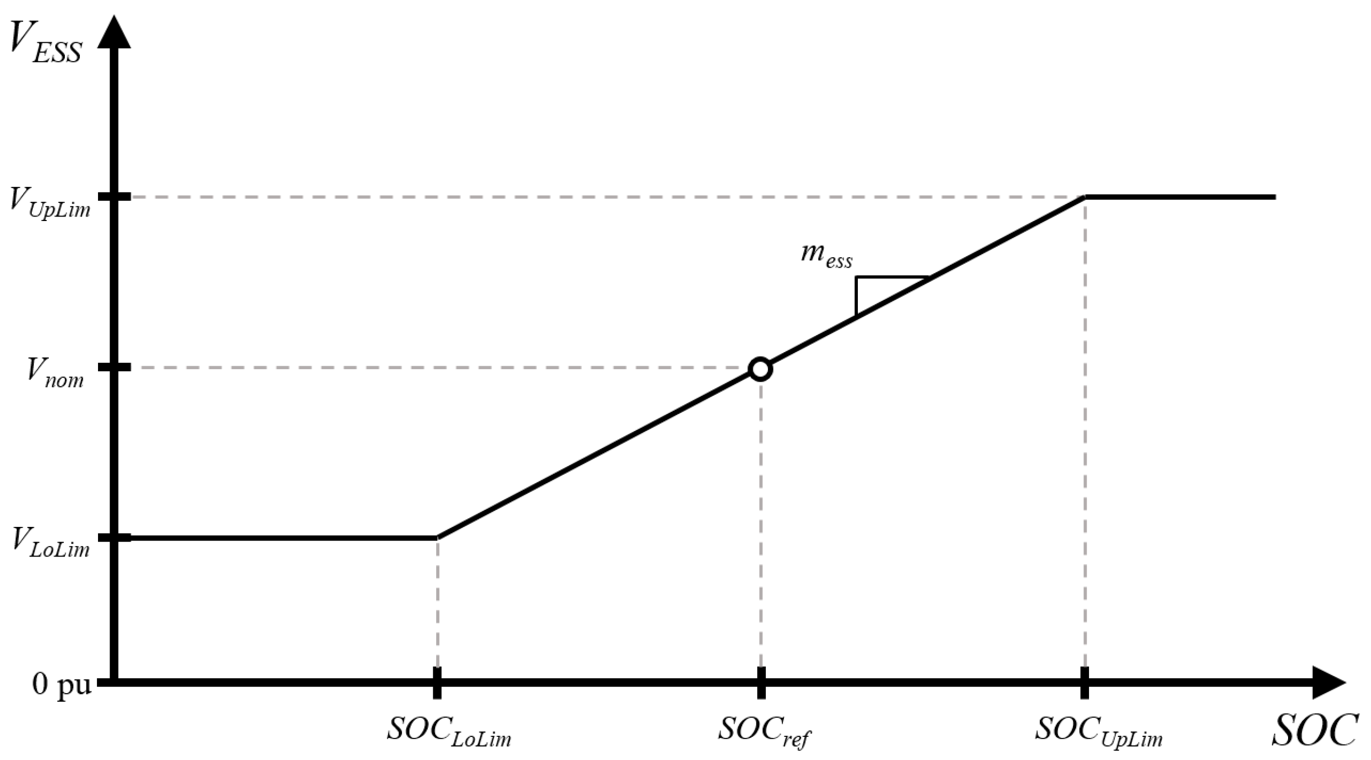
2.1. Control Scheme of Energy Storage System
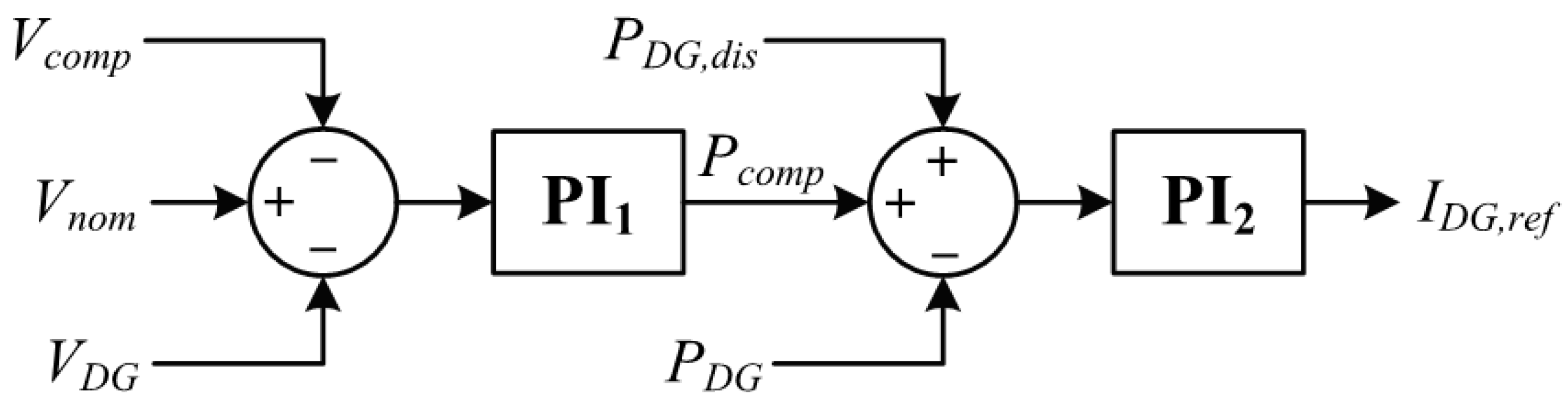
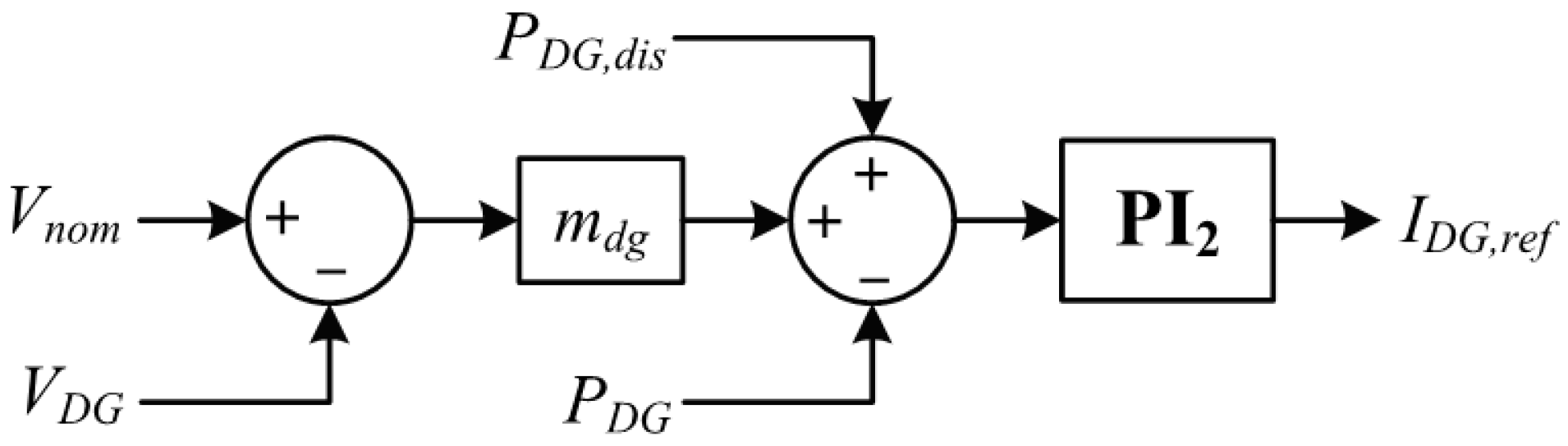
2.2. Control Scheme of Distributed Generation
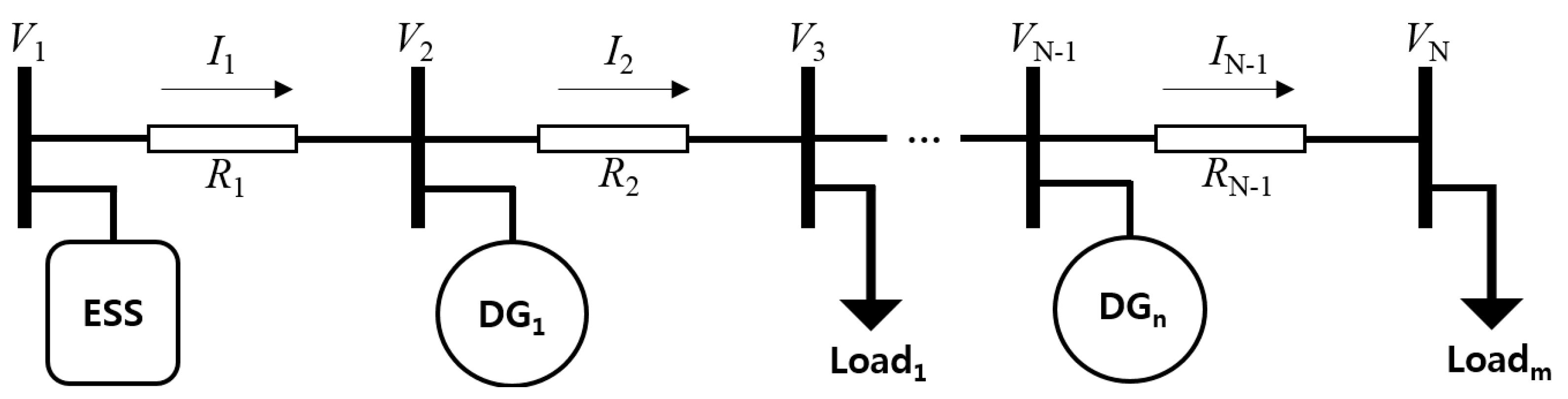
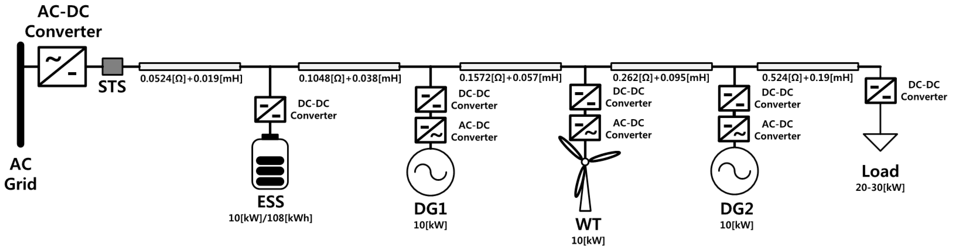
3. System Configuration
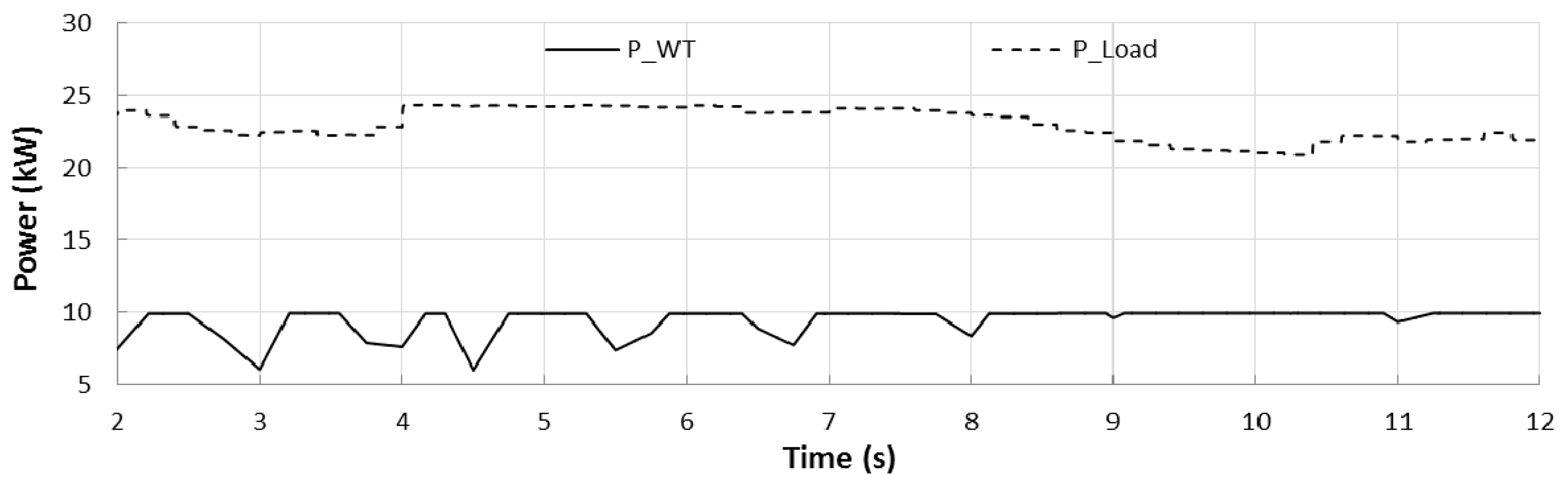
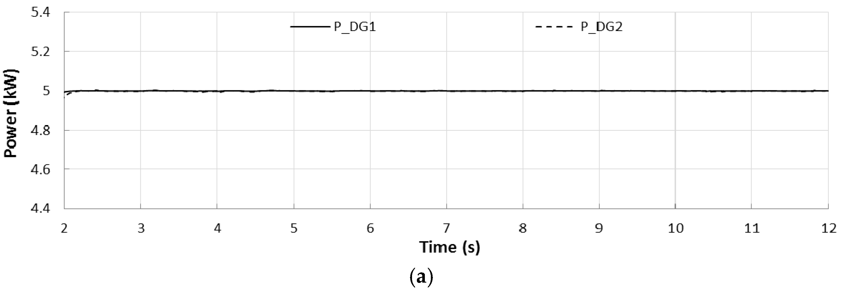
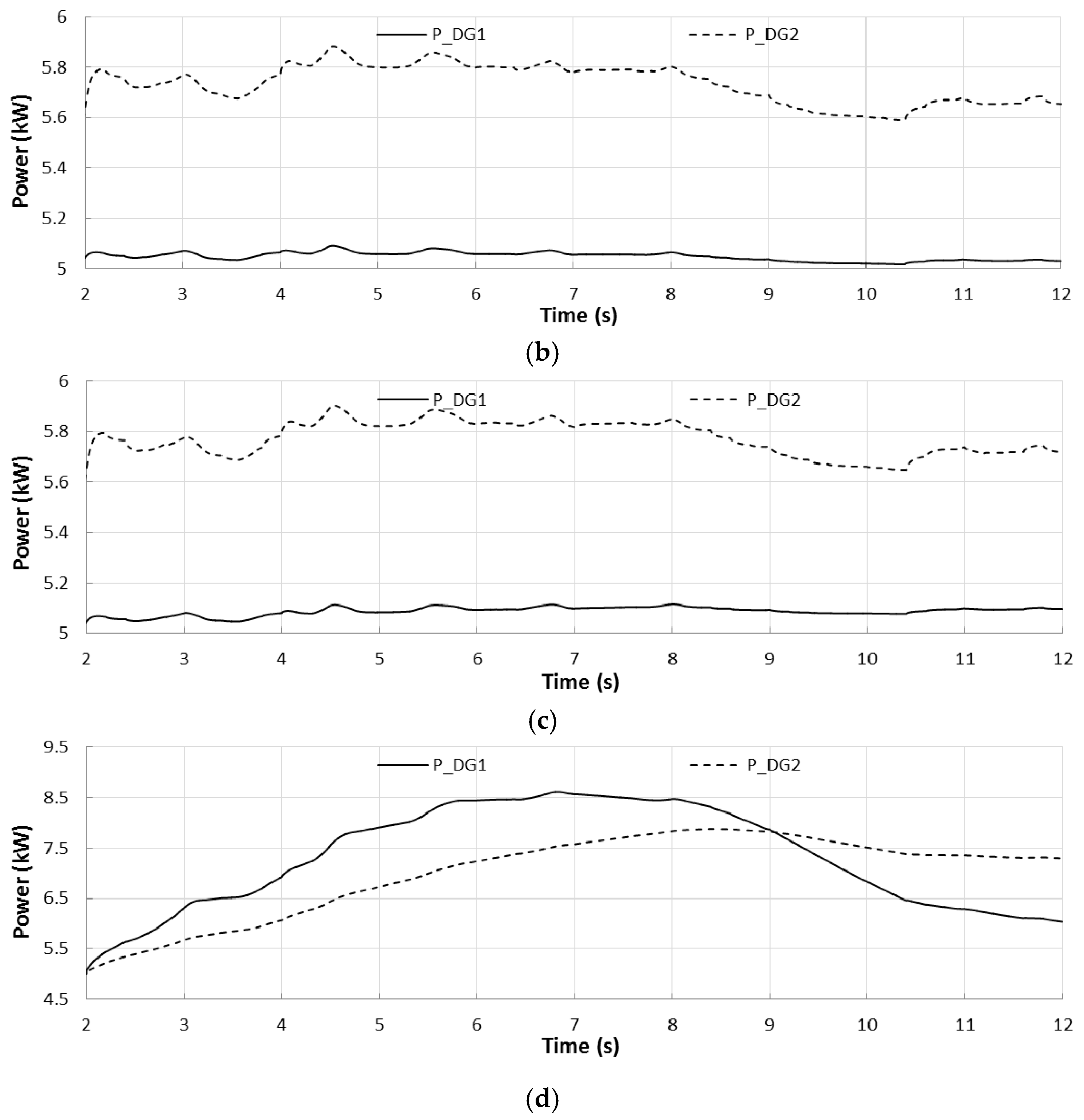
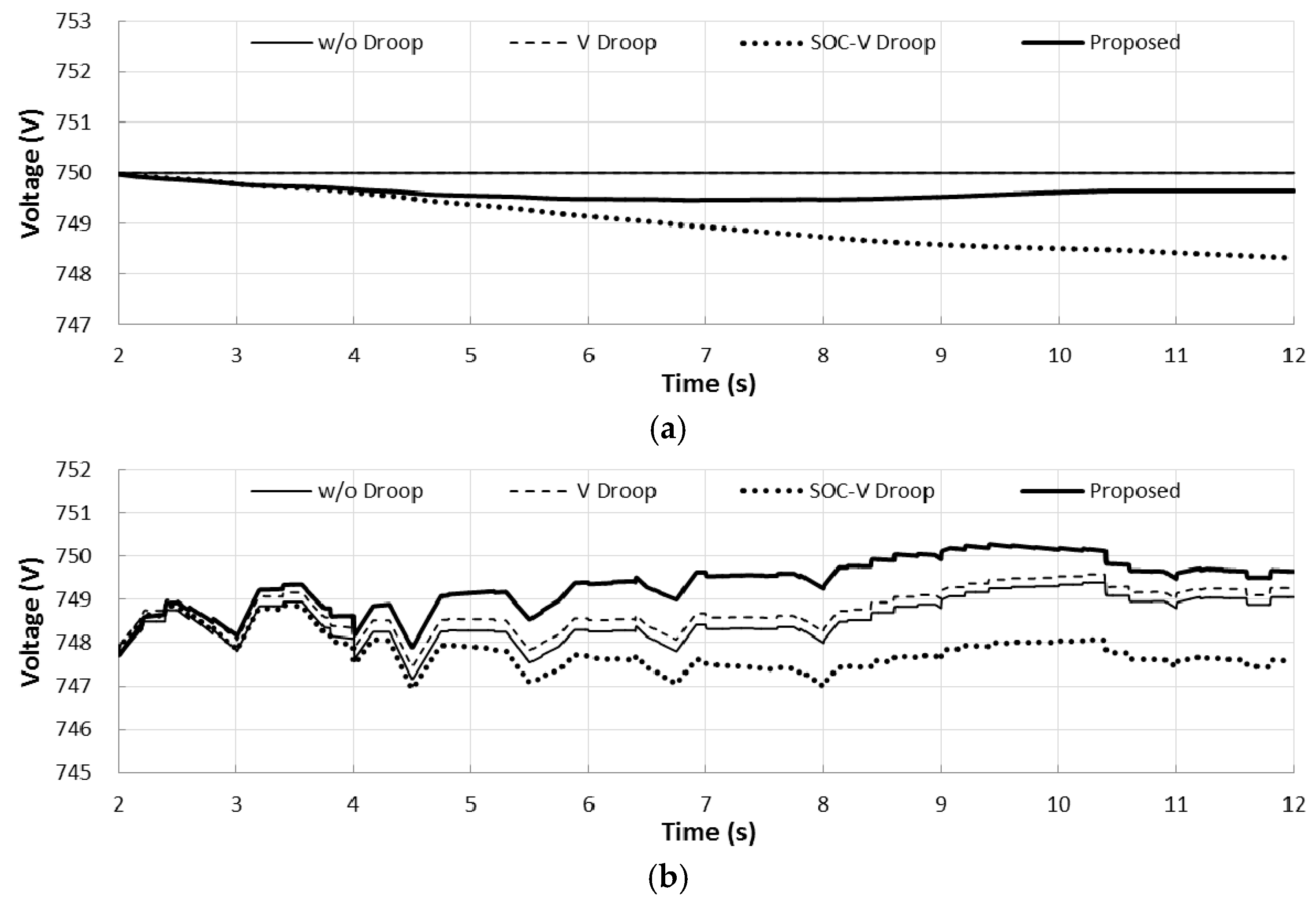
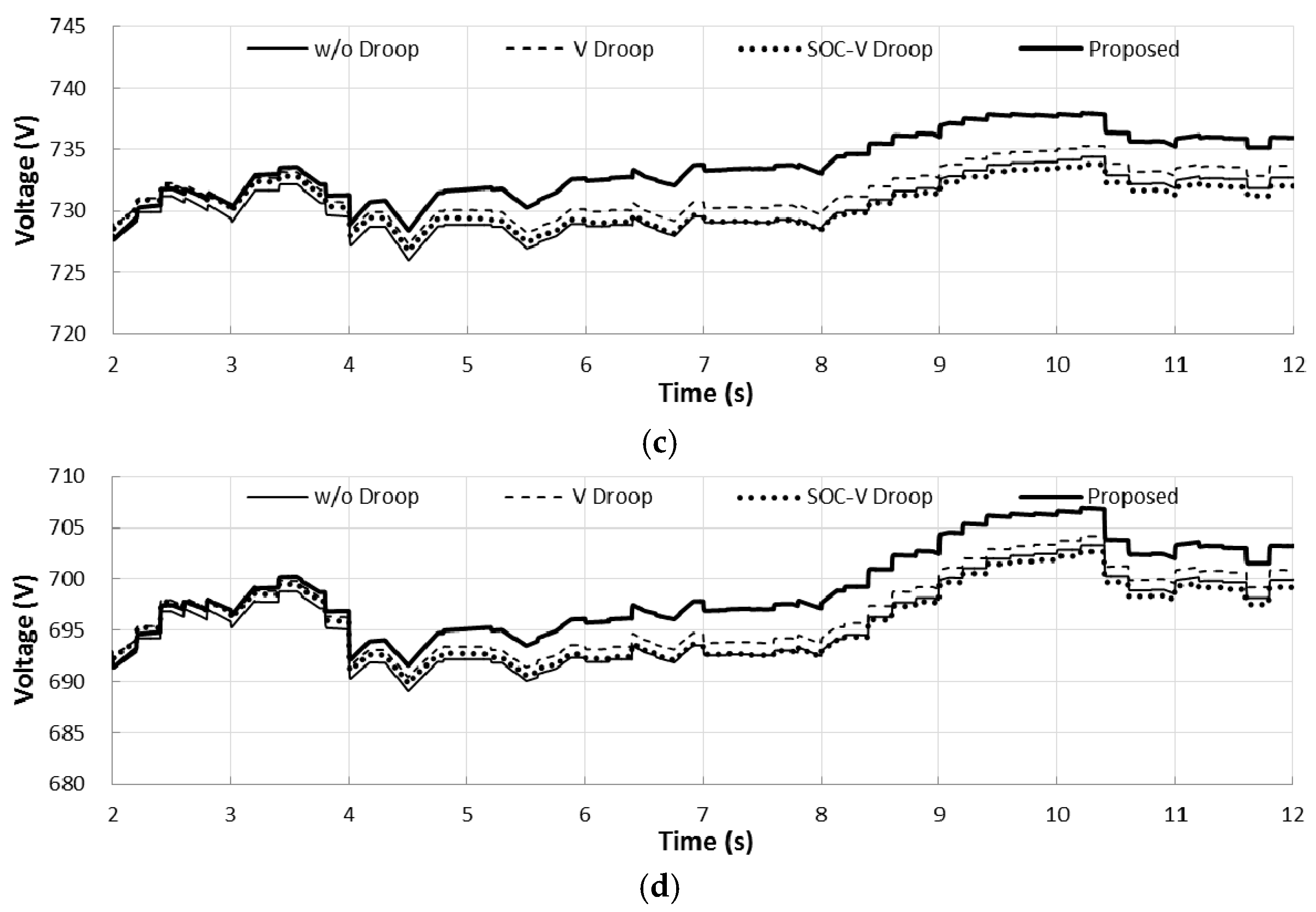
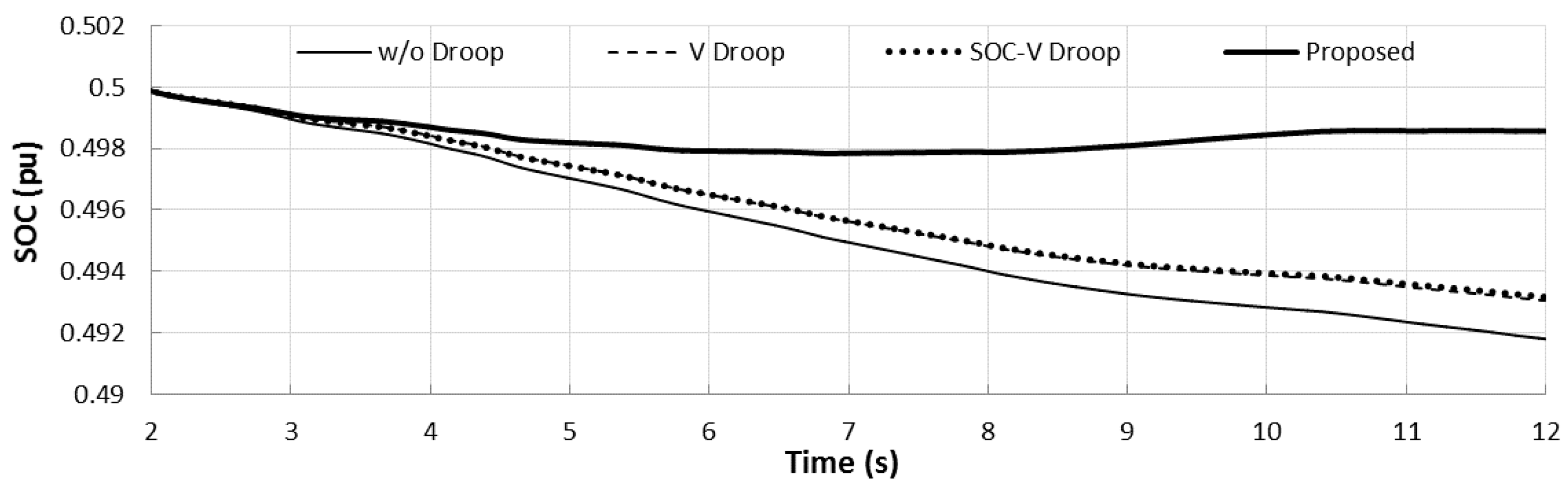
4. Simulation Results and Discussion
- Control method without droop (w/o Droop): The ESS is controlled to output constant voltage (nominal voltage) and the dispatchable DGs (DG1 and DG2) are controlled to output dispatched power only.
- Voltage droop control method (V Droop): The voltage droop control shown in Figure 6 is applied to the DGs. The droop coefficient mdg is set to 3 in this study.
- SOC-voltage droop and voltage droop control method (SOC-V Droop): SOC-voltage droop control shown in Figure 1 is applied to the ESS and the voltage droop control is applied to the DGs.
5. Conclusions
Acknowledgments
Author Contributions
Conflicts of Interest
Nomenclature
| AC | Alternating current |
| BESS | Battery energy storage system |
| DC | Direct current |
| DG | Distributed generation |
| EMS | Energy management system |
| ESS | Energy storage system |
| MPPT | Maximum power point tracking |
| PI | Proportional-integral |
| PV | Photovoltaic |
| RES | Renewable energy source |
| SOC | State of charge |
| SOC-V | State of charge-voltage |
| STS | Static switch |
| WT | Wind turbine |
| PESS | Output power of the energy storage system |
| Prate, Crate, IESS,rate | Rating power, capacity, current of the energy storage system |
| VESS, IESS | Output voltage and current of the energy storage system |
| mess | State of charge-voltage droop coefficient |
| Vnom | Nominal value of the grid voltage |
| VUpLim, LoLim | Upper and lower limits of the grid voltage |
| SOCi, SOCref | Initial and reference values of the state of charge |
| SOCUpLim, SOCLoLim | Upper and lower limits of the grid voltage |
| PDG, PDG,dis | Output and dispatched value of distributed generation active power |
| Pcomp | Active power to compensate the state of charge deviation from the reference value |
| Vcomp | Compensation voltage to compensate line voltage drop across the resistance between the ESS bus and the distributed generation bus |
| IDG,ref | Reference output current of distributed generation |
| VDG | Voltage at distributed generation bus |
| ILoadi,forc | Forecasted current of the load at bus i |
| IDGi,forc | Forecasted current of the distributed generation at bus i |
| VESS,est | Estimated voltage of energy storage system output voltage |
| Vi | Voltage magnitude at bus i |
| Ii | Current flow from bus i to bus i+1 |
| Ii,est | Estimate current flow from bus i to bus i+1 |
| Ri | Resistance of line between bus i and i+1 |
| N | Total number of the buses |
| n | Total number of the distributed generations |
References
- Lu, D.D.C.; Agelidis, V.G. Photovoltaic-battery-powered DC bus system for common portable electronic devices. IEEE Trans. Power Electron. 2012, 24, 849–855. [Google Scholar] [CrossRef]
- Inamori, J.; Hoshi, H.; Tanaka, T.; Babasaki, T. 380-VDC power distribution system for 4-MW-scale cloud facility. In Proceedings of the IEEE 36th International Telecommunications Energy Conference, Vancouver, BC, Canada, 28 September–2 October 2014.
- Hammerstrom, D.J. AC versus DC distribution systems—Did we get it right? In Proceedings of the IEEE Power Engineering Society General Meeting, Tampa, FL, USA, 24–28 June 2007.
- Jeon, J.-Y.; Kim, J.-S.; Choe, G.-Y.; Lee, B.-K.; Hur, J.; Jin, H.-C. Design guideline of DC distribution systems for home appliances: Issues and solution. In Proceedings of the IEEE International Electric Machines and Drive Conference, Niagara Falls, ON, Canada, 15–18 May 2011.
- Shimomachi, K.; Hara, R.; Kita, H. Comparison between DC and AC microgrid systems considering ratio of DC load. In Proceedings of the IEEE PES Asia-Pacific Power and Energy Engineering Conference, Brisbane, Australia, 15–18 November 2015.
- Whaite, S.; Grainger, B.; Kwasinski, A. Power quality in DC power distribution systems and microgrids. Energies 2015, 8, 4378–4399. [Google Scholar] [CrossRef]
- Electric Power Research Institute (EPRI). DC Power Production, Delivery and Utilization; EPRI: Palo Alto, CA, USA, 2006. [Google Scholar]
- Olivares, D.E.; Mehrizi-Sani, A.; Etemadi, A.H.; Canizares, C.A.; Iravani, R.; Kazerani, M.; Hajimiragha, A.H.; Gomis-Bellmunt, O.; Saeedifard, M.; Palma-Behnke, R.; et al. Trends in microgrid control. IEEE Trans. Smart Grid 2014, 5, 1905–1919. [Google Scholar] [CrossRef]
- Xiao, J.; Wang, P.; Setyawan, L. Multilevel energy management system for hybridization of energy storage in DC microgrids. IEEE Trans. Smart Grid 2016, 7, 847–856. [Google Scholar] [CrossRef]
- Chen, Y.-K.; Wu, Y.-C.; Song, C.-C.; Chen, Y.-S. Design and implementation of energy management system with fuzzy control for DC microgrid systems. IEEE Trans. Power Electron. 2013, 28, 1563–1570. [Google Scholar] [CrossRef]
- Karavas, C.S.; Kyriakarakos, G.; Arvanitis, K.G.; Papadakis, G. A multi-agent decentralized energy management system based on distributed intelligence for the design and control of autonomous polygeneration microgrids. Energy Convers. Manag. 2015, 103, 166–179. [Google Scholar] [CrossRef]
- Kyriakarakos, G.; Piromalis, D.D.; Dounis, A.I.; Arvanitis, K.G.; Papadakis, G. Intelligent demand side energy management system for autonomous polygeneration microgrids. Appl. Energy 2013, 103, 39–51. [Google Scholar] [CrossRef]
- Lie, X.; Chen, D. Control and operation of a DC microgrid with variable generation and energy storage. IEEE Trans. Power Deliv. 2011, 26, 2513–2522. [Google Scholar]
- Fu, Y.; Zhang, Z.; Wang, Y.; Yu, M.; Hei, Y.; Meng, J.; Wang, H. Research on power coordinated control of wind turbine-based DC microgrid under various modes. In Proceedings of the 2016 IEEE 8th IPEMC-ECCE Asia, Hefei, China, 22–26 May 2016; pp. 1480–1484.
- Papadimitriou, C.N.; Kleftakis, V.A.; Rigas, A.; Hatziargyriou, N.D. DC-microgrid control strategy using DC-bus signaling. In Proceedings of the MedPower, Athens, Greece, 2–5 November 2014.
- Dragicevic, T.; Guerrero, J.M.; Vasquez, J.C.; Skrlec, D. Supervisory control of an adaptive-droop regulated DC microgrid with battery management capability. IEEE Trans. Power Electron. 2014, 29, 695–706. [Google Scholar] [CrossRef]
- Gao, L.; Liu, S.; Dougal, R.A. Dynamic lithium-ion battery model for system simulation. IEEE Trans. Compon. Packag. Technol. 2002, 25, 495–505. [Google Scholar]
- Kumar, P.; Singh, A.K. Grid Codes: Goals and Challenges. In Renewable Energy Integration, 1st ed.; Hossain, J., Mahmud, A., Eds.; Springer: Singapore, 2014; pp. 17–39. [Google Scholar]
- Saft Inc. Lithium-ion Battery Life Technical Sheet; Saft Inc.: Bagnolet, France, 2014. [Google Scholar]


| DG/Load | Forecasted Power (kW) | Estimated Current (A) |
|---|---|---|
| DG1 | 5 | 6.67 |
| DG2 | 5 | 6.67 |
| WT | 9 | 12 |
| Load | 23 | 30.67 |
© 2016 by the authors; licensee MDPI, Basel, Switzerland. This article is an open access article distributed under the terms and conditions of the Creative Commons Attribution (CC-BY) license (http://creativecommons.org/licenses/by/4.0/).
Share and Cite
Hwang, C.-S.; Kim, E.-S.; Kim, Y.-S. A Decentralized Control Method for Distributed Generations in an Islanded DC Microgrid Considering Voltage Drop Compensation and Durable State of Charge. Energies 2016, 9, 1070. https://doi.org/10.3390/en9121070
Hwang C-S, Kim E-S, Kim Y-S. A Decentralized Control Method for Distributed Generations in an Islanded DC Microgrid Considering Voltage Drop Compensation and Durable State of Charge. Energies. 2016; 9(12):1070. https://doi.org/10.3390/en9121070
Chicago/Turabian StyleHwang, Chul-Sang, Eung-Sang Kim, and Yun-Su Kim. 2016. "A Decentralized Control Method for Distributed Generations in an Islanded DC Microgrid Considering Voltage Drop Compensation and Durable State of Charge" Energies 9, no. 12: 1070. https://doi.org/10.3390/en9121070
APA StyleHwang, C.-S., Kim, E.-S., & Kim, Y.-S. (2016). A Decentralized Control Method for Distributed Generations in an Islanded DC Microgrid Considering Voltage Drop Compensation and Durable State of Charge. Energies, 9(12), 1070. https://doi.org/10.3390/en9121070