Abstract
Increasing traffic loads and changes in code provisions lead to deficits in shear and flexural capacity of many existing highway bridges. Therefore, a large number of structures are expected to require refurbishment and strengthening in the future. This projection is based on the current condition of many older road bridges. Different strengthening methods for bridges exist to extend their service life, all having specific advantages and disadvantages. By applying a thin layer of carbon textile-reinforced mortar (CTRM) to bridge deck slabs and the webs of pre-stressed concrete bridges, the fatigue and ultimate strength of these members can be increased significantly. The CTRM layer is a combination of a corrosion resistant carbon fiber reinforced polymer (CFRP) fabric and an efficient mortar. In this paper, the strengthening method and the experimental results obtained at RWTH Aachen University are presented.
1. Introduction
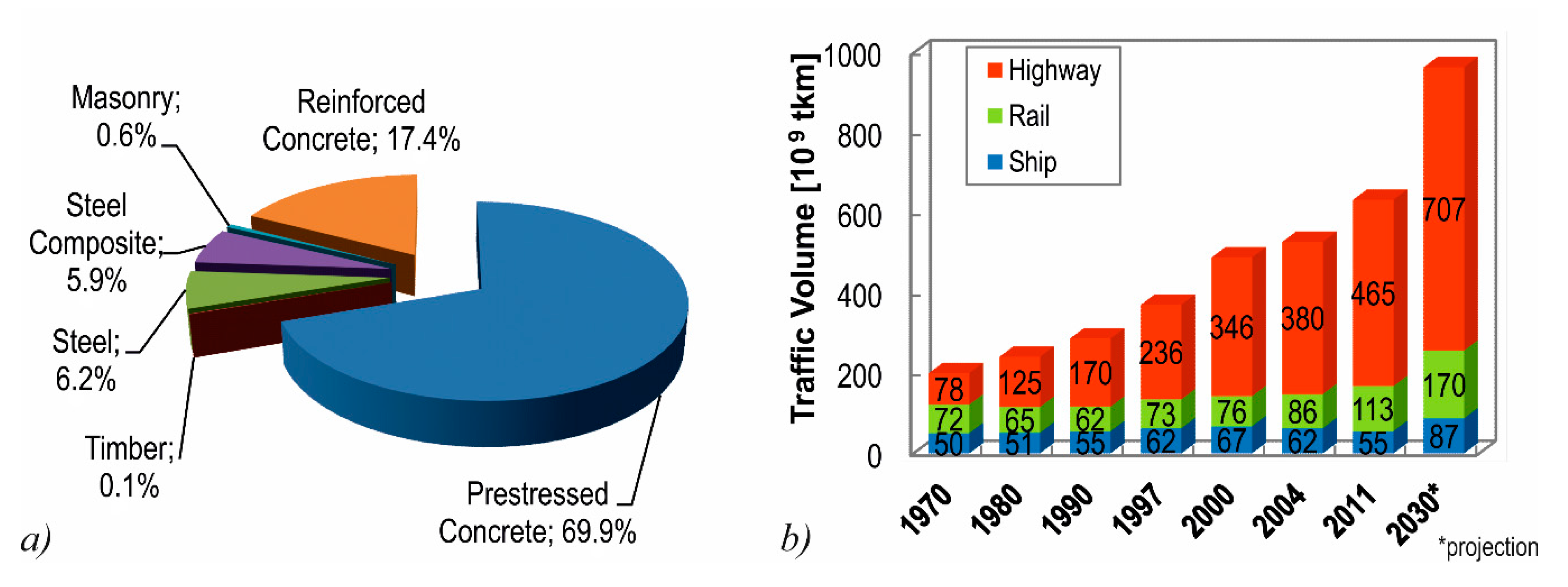
As an essential part for the national infrastructure, the German Federal Highway System comprises about 39,000 bridge structures. In terms of the bridge deck area, almost 90% of these bridges are made of reinforced or pre-stressed concrete [1] (Figure 1a). The traffic volume on these bridges has been increasing over the past decades, particularly concerning heavy goods traffic [2,3], and is expected to further increase in the future [4] (Figure 1b). Especially, abnormal traffic loads and unapproved excessive charges lead to bridges loaded to their design capacity or beyond [5].
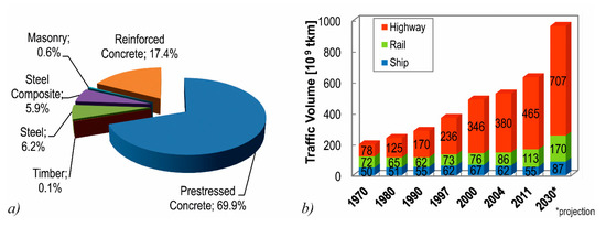
Figure 1.
(a) German Federal Highway Bridges in terms of bridge deck area [1]; and (b) heavy goods traffic volume in Germany [4].
This results in an accelerated deterioration of these structures, as well as to deficits concerning the integrity according to the applicable code provisions. The aforementioned problems are quite common in western countries [6,7,8,9]. In Germany, the shear design check is critical in most cases [10,11,12]. One reason is that many bridges have been designed according to the so-called principle tensile stress criterion (thus requiring no shear reinforcement). The required minimum shear reinforcement then was less than it is today [13,14]. Although guidelines for the recalculation and assessment of existing bridges have been developed [15,16], and further refinements in shear design models can lead to a significantly higher shear capacity [17,18,19], severe damage often leads to instantaneous need for action, since the damage often has already progressed.
Different strengthening and rehabilitation measures with individual advantages and disadvantages are available to extend the service life of bridges [20]. One of the most common strengthening measures to avoid traffic obstructions is the use of additional post-tensioning in the longitudinal direction [21]. Research has revealed, however, that additional post-tensioning only slightly increases the ultimate shear capacity [14,22]. To provide innovative solutions to the given problems, the use of an additional mortar layer with non-corrosive reinforcement made from carbon fibers is investigated at RWTH Aachen University. This material is called carbon-textile-reinforced mortar (CTRM) and could serve as a conservation method and as a retroactive supplement to the overused mild reinforcement. In the past, the general load-bearing behavior of textile-reinforced concrete (TRC) has been investigated in numerous research projects [23,24,25,26,27]. In the long-term, TRC has the potential of replacing regularly-reinforced concrete in many applications [11,28], e.g., for use in new and filigree structures [29,30,31,32,33,34,35]. The strengthening of existing structures with CTRM or TRC is also currently investigated and has already been successfully applied [36,37,38,39].
The effect of an additional CTRM layer for the webs of pre-stressed concrete beams under cyclic and static loading [40] and for bridge deck slabs [41] is presented within this paper. Previous investigations on RC beams under cyclic loading are described in [42]. The CTRM layer is composed of a carbon fiber reinforced polymer (CFRP) fabric and an efficient mortar. CFRP is corrosion resistant and has a significantly higher tensile strength than rebar steel. Therefore, thin structural components with high strengths can be realized. Reinforced concrete slab segments (h = 0.28 m) were strengthened to investigate the effect of an additional CTRM layer on the shear and flexural strength of bridge deck slabs. In addition, the webs of two pre-stressed concrete beams (l = 6.5 m, h = 0.7 m) were strengthened with CTRM and tested under cyclic and static loading to investigate the effect on the shear strength of the longitudinal system. In this paper, the impact of strengthening layers on the members’ strength is presented.
2. CTRM Layer for Bridge Deck Slabs
2.1. Concept
With respect to bridge deck slabs, the CTRM layer is called Smart-Deck, as it combines the following three features: all-over real-time humidity monitoring, a preventive cathodic corrosion protection (CCP), and a strengthening effect in the transverse direction of the bridge. Smart-Deck is applied between the surface of the reinforced concrete bridge deck slab and the road surface (Figure 2a). It is installed in segments to obtain defined sectors in the longitudinal direction, which allows for locating possible leaks in the road surface. The monitoring function provides the detection of leaks at an early stage long before severe damage occurs. Due to the possibility of engaging the CCP, the replacement of the damaged road surface can be postponed and realized in convenient periods of low traffic. This allows for an adequate planning horizon and, thus, lower expenses. The bending and strengthening effect of Smart-Deck counteracts the increase in traffic volume and, therefore, extends the remaining service life of the bridge.

Figure 2.
(a) Application of Smart-Deck; and (b) the position of sawn segments in a demonstrator slab.
The additional CTRM layer consists of two layers of an epoxy-resin impregnated carbon grid and a high-performance mortar. The carbon reinforcement is equipped with electrical connections for the monitoring and the CCP. The mortar cover is 10 mm thick on both sides, the two reinforcement layers are installed at a distance of 15 mm which makes a total of 35 mm thickness of the additional CTRM layer. Different combinations of mortar and CFRP were tested in an iterative process to meet all requirements of the project. The test specimens presented in this paper were strengthened with a carbon grid with a mesh opening of e = 38 mm, a cross-section area of atex = 140 mm²/m and a special epoxy-resin that was complemented with carbon nanotubes (CNT) in order to increase the electrical conductivity (ft,tex ≈ 2200 MPa; Etex ≈ 215,000 MPa) [43]. In addition, a mortar with a maximum aggregate size of 4 mm that is both flowable and stable enough to gaplessly surround the textile reinforcement was used. The mortar was also required to make for a high conveyor capability, on one hand, and to allow the implementation of an inclination of the surface of at least 2.5%, on the other. The mechanical properties of the mortar were determined on prisms with a length of 160 mm and a width and height of 40 mm. The flexural tensile strength fct,flex amounted to 10.4 MPa and the compressive strength fcm,prism to 65.9 MPa, respectively.
2.2. Preparation of the Test Specimens
A demonstrator slab was prepared to investigate the implementability under realistic conditions of a construction site on a bridge, the functionality of the monitoring and CCP and the additional strength by Smart-Deck. For this purpose, an approximately 80 m² large RC slab with a height of 0.28 m was built (fc,cyl = 58 MPa (hcyl = 300 mm; Dcyl = 150 mm) at time of tests). After four months of curing, the surface was pre-treated with shot peening to increase its roughness for a better bond in the interface between the existing RC structure and the additional CTRM layer. Afterwards, Smart-Deck was applied. In the first step, the carbon grid was secured in place by plastic dowels that were fixed to the RC slab. The mortar was then cast employing a feed hose that was connected to an automatic mixing unit where water was added to dry mortar stored in a silo. The RC slab was reinforced using different longitudinal reinforcement ratios in each third. The respective segments contained 5.24 cm²/m (using bars of Ø = 10 mm every 15 cm), 10.3 cm²/m (Ø14/15), and 25.13 cm²/m (Ø16/8) steel reinforcement (characteristic yield strength fyk ≈ 500 MPa). No stirrups or other shear reinforcement elements were used. In order to investigate the strengthening effect of Smart-Deck, two segments were sawn out from the slab in the area of the lowest and highest reinforcement ratio, respectively (Figure 2b). Since no CTRM layer was applied on the edge areas, where two segments were located, each test on a strengthened slab segment had a non-strengthened reference test.
By investigating members with two different steel reinforcement ratios, the varying conditions in existing bridges were represented. Additionally, different failure modes can be expected since the test specimens with low reinforcement ratios fail in flexure while shear failure governs in specimens with higher reinforcement ratios. Along the cut surfaces of the sawn segments, the position of the CFRP grid was examined (Figure 3a). No significant deviation of the intended position was observed.

Figure 3.
(a) Detail of a cut surface; and (b) a bridge loaded by a truck and the idealized load setup.
2.3. Investigation of the Strengthening Effect
Within the scope of the load bearing tests, a truck located on a bridge’s cantilever was simulated, as shown in Figure 3b. For this purpose, the specimens were simply supported with a distance of 1.70 m between the axles of the supports. The resulting cantilevers of 2.25 m were separately loaded in two partial tests. The support that was more distant from the load was arranged at the topside of the specimen in order to counteract the lifting forces that occurred due to the test setup. The load was induced employing a hydraulic cylinder and a load distribution plate with an area of 40 × 40 cm. These measurements represent the contact surface of a wheel load according to Eurocode 1 [44]. The distance a between the center line of the load and the axis of the support according to Figure 4 was 0.7 m, 1.0 m and 1.3 m to investigate the influence of different a/d-ratios (corresponding to the shear-slenderness) within the shear tests and to vary the level of the bending moment within the flexural tests, respectively. Table 1 gives an overview over the parameters of the test program.

Figure 4.
Test setup.

Table 1.
Amount of CTRM and steel, effective depth ds of the RC slab and the load distance a.
All specimens were loaded until failure. Within the shear tests, a characteristic diagonal shear crack occurred (Figure 5). At failure, the cracks opened widely. Regarding the tests on strengthened specimens, a significantly larger number of bending cracks appeared, featuring smaller crack widths compared to the non-strengthened reference tests, like the crack patterns at failure of SD-K3-1 and SD-K4-1, exemplarily shown in Figure 5.

Figure 5.
Crack pattern of (a) SD-K3-1; and (b) SD-K4-1.
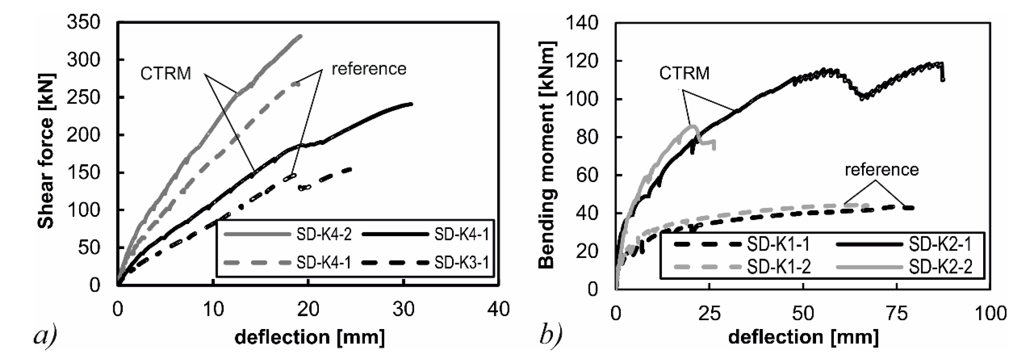
Figure 6 shows the load-deformation-curves of the tests. The deflections were measured below the center of the load application. All tests on the strengthened slab segments feature lower deformations compared to their reference tests at the same load level. Within the bending tests on the strengthened specimens, local delamination between the carbon grid and the surrounding mortar occurred. Subsequent modifications of the materials by the project partners aim to prevent this phenomenon. In the shear tests (SD-K3 and SD-K4), the increases in shear capacity were ηV,1 = 56% and ηV,2 = 23% (η = (Vu,TRC − Vu,RC)/Vu,RC), respectively. The increase in flexural capacity within the bending tests was significantly higher. The flexural strengthening rates were ηM,1 = 174% and ηM,2 = 91% (η = (Mu,CTRM − Mu,RC)/Mu,RC), respectively. Table 2 gives an overview of the test results.
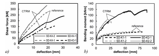
Figure 6.
(a) Load-deflection-curve of shear tests; and (b) the load deflection curve of the bending tests.

Table 2.
Maximum bending/shear capacity Mmax/Vmax, maximum deflection wmax, and strengthening degree η.
These tests show that Smart-Deck, in principle, provides an increased flexural and shear strength of concrete bridge deck slabs. The findings of these experimental investigations and the other experiences made within the scope of the implementation of the entire slab provide important information regarding further development of the materials. Further investigations are in preparation. Other shear tests will be carried out, as well as flexural tests on slab segments with lower reinforcement ratios. Additionally, one shear and one bending test under cyclic loading are currently planned in order to investigate the load-bearing behavior of the strengthened member under fatigue loading.
3. Strengthening of Webs with a CTRM layer
3.1. Concept and Preliminary Investigations
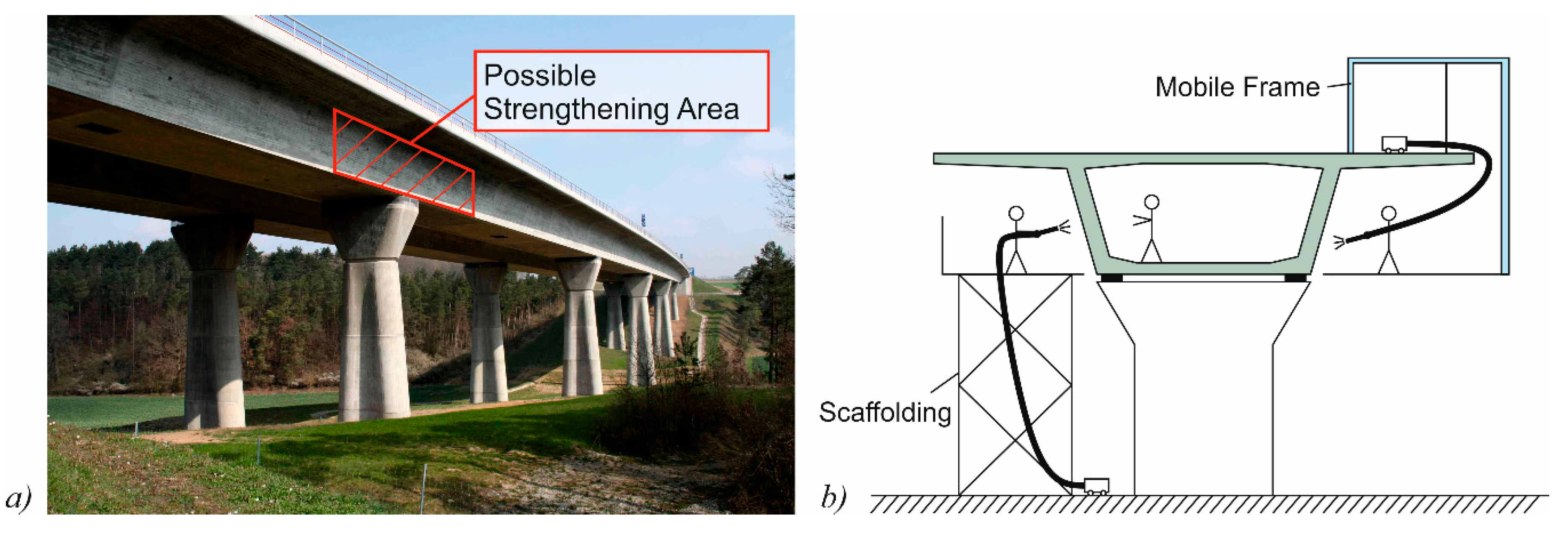
The possibility of strengthening the webs of pre-stressed concrete bridges was investigated in cyclic and static shear tests on pre-stressed concrete beams [40,41]. This method allows for a local strengthening of critical areas, mostly in the vicinity of bridge columns instead of the whole structure (Figure 7a). The main advantage of local strengthening is the reduced effort, and especially the reduced dead load that is added to the structure. For experimental validation, pre-stressed concrete beams with an I-shaped cross-section were strengthened on the webs using a CTRM layer. The CTRM layer consists of a carbon fiber grid in combination with a sprayed mortar. In its load-bearing behavior, an I-shaped cross-section resembles common pre-stressed box girder bridges (Figure 7b), for which this strengthening method could be utilized. In the test specimens, an elaborate anchoring of the strengthening layer in the top and bottom chord was omitted. According to the truss analogy, a strengthening-layer without anchorage in the chords should have little to no effect on the ultimate shear strength. Nevertheless, a strengthening effect of a grid reinforced layer can be expected according to yield line theory [45], especially due to the rovings in the horizontal direction.
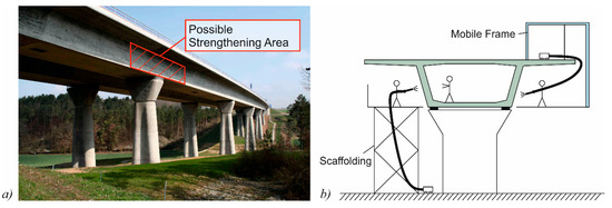
Figure 7.
(a) Possible are of CTRM strengthening (image edited by the authors, “A71-Thalwassertalbruecke”, author: Störfix, licensed under CC BY-SA 3.0); and (b) the application method.
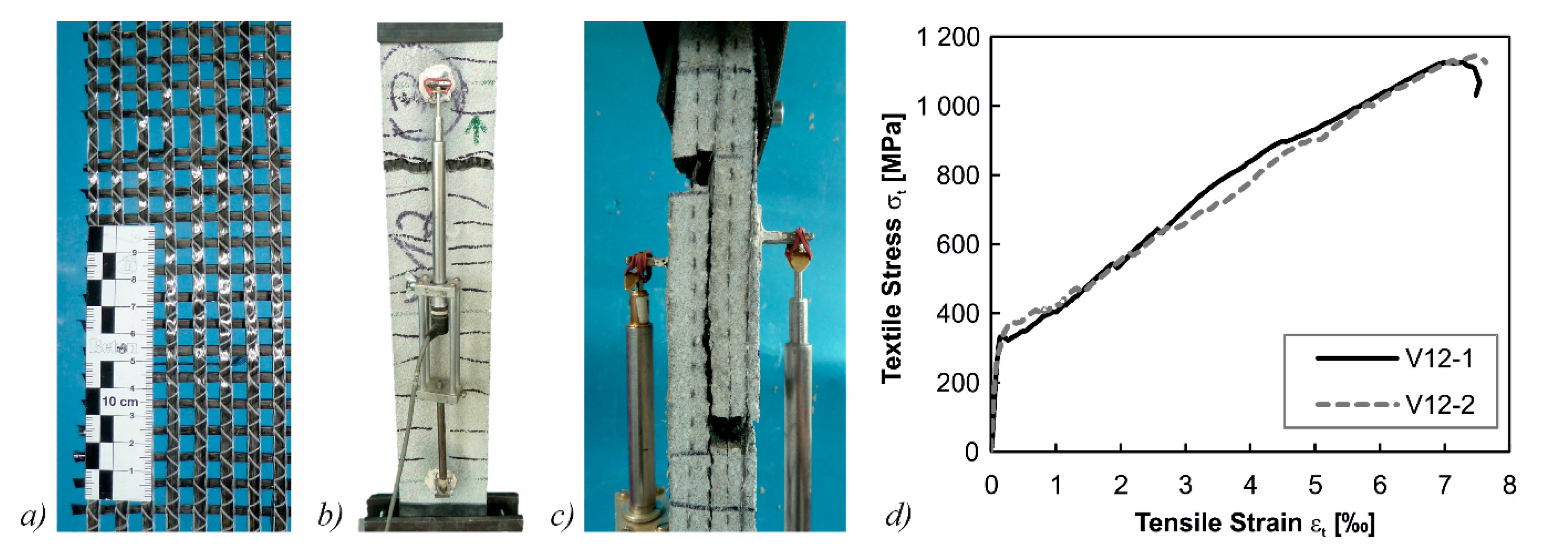
In a first step, an adequate combination of sprayed mortar and textile material for the strengthening of the beams had to be found. For this, tensile tests similar to [46] were conducted on specimens with dimensions of 100 mm width, 880 mm length, and a thickness of 25 to 30 mm (Figure 8b,c). Combinations of two different matrices and one to four layers of textile grid (alkali-resistant glass/carbon impregnated with epoxy resin/styrene-butadiene/un-impregnated carbon grid) were investigated. In Table 3, the different mean values of the maximum tensile stresses in the textile for different combinations of parameters are summarized. In the end, polymer-modified dry-spray mortar (SPCC) with a maximum aggregate size of dag = 2 mm and an unimpregnated carbon grid with an area of atex = 55 mm²/m was used as the textile reinforcement material (Figure 8a). The mean tensile strength of the carbon grid in these tests was σt = 1136 MPa (Figure 8d).
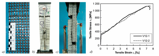
Figure 8.
(a) Unimpregnated carbon textile; (b) tensile test setup; (c) pull-out of rovings after failure; and (d) stress-strain relationships of tensile tests with an un-impregnated carbon grid.

Table 3.
Mean values of maximum textile stresses in the tensile tests for different textile materials and sprayed mortars.
3.2. Test Specimens and Test Setup
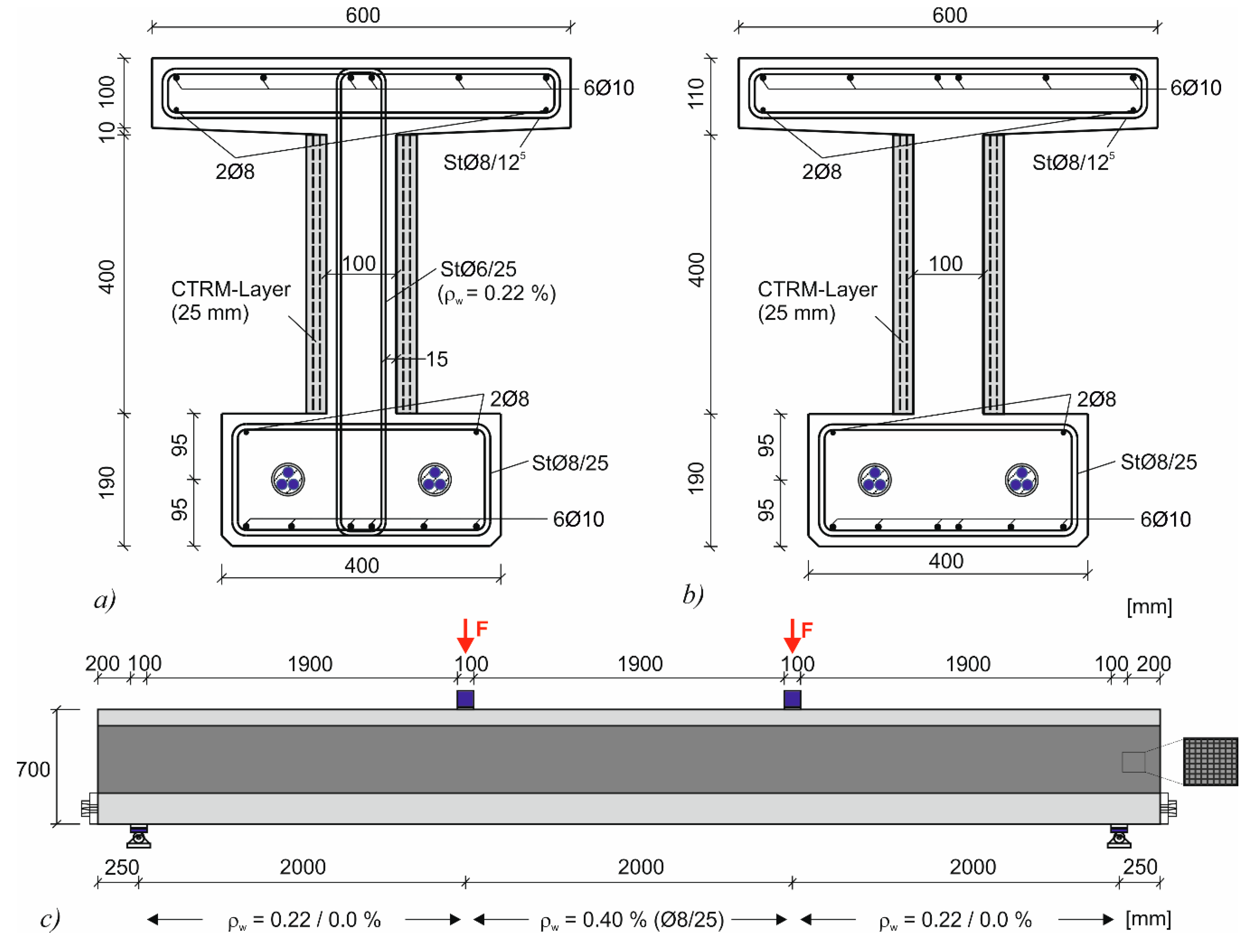
The experimental results of the strengthened test beams were compared to similar test beams from previous research projects without a CTRM layer which served as a reference [47,48]. The cross-section of the test beams had a total width of 0.6 m and a web width of 0.1 m (Figure 9a,b). The beams had a total length of 6.5 m and cross-section height of 0.7 m (Figure 9c). The point loads were located in the third points of the beam with a resulting shear slenderness of a/d = 3.3. The tests were performed on a member with a low amount of shear reinforcement (ρw = 0.22%) which was strengthened with CTRM (CTRM-M-22-7). This member was compared to identical members without strengthening (M-22-7 and M-22-3) from a previous project [48]. Another member without shear reinforcement with CTRM-strengthening was produced (CTRM-I-O-5) which was also previously tested without strengthening (I-O-5) [47]. The test beams were subjected to 1.2 to 3.1 million load cycles using different peak and valley loads. In difference to tests by other authors [42], the strengthening layer was not anchored the compression or tension chord.
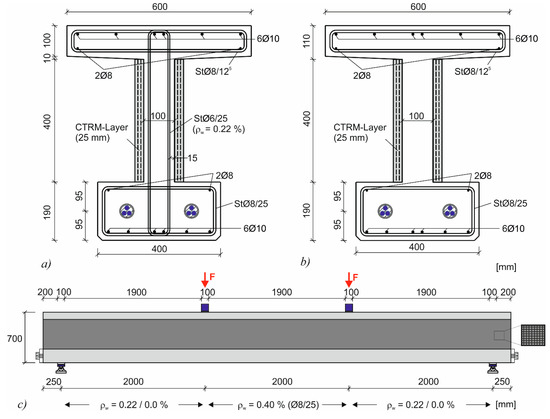
Figure 9.
(a) Strengthened cross-section with shear reinforcement (CTRM-M-22-7); (b) the strengthened cross-section without shear reinforcement (CTRM-I-O-5); and (c) the longitudinal system.
3.3. Material Properties
Normal strength concrete with a maximum aggregate size of 8 mm was used. In Table 4 the mechanical concrete and shotcrete properties at the time of testing of the specimens are given. The number of test specimens is given in brackets. The cylinder strength fcm,cyl and the splitting tensile strength fct,split were determined on cylinders with h = 300 mm and a diameter of d = 150 mm. The cube strength fcm,cube was determined on cubes with an edge length of 150 mm. The axial tensile strength fct,ax was determined on drilled cores with h = 90 mm and d = 45 mm that were either drilled from the web of the beams or a flexural tensile test specimen. The mechanical properties of the shotcrete were determined on prisms with a length of 160 mm and a width and height of 40 mm. After testing the flexural tensile strength fct,flex, the compressive strength fcm,prism was determined from the remaining prismatic samples.

Table 4.
Mechanical properties of the concrete used in beams and the spray mortar.
The mild steel reinforcement in each beam consisted of normal strength steel bars (fyk = 500 MPa). The mechanical properties of the shear reinforcement are given in Table 5. The beams were pre-stressed using two tendons, each consisting of three 0.6” (15.2 mm) strands of pre-stressing steel St1570/1770 with a cross-sectional area of 3 × 140 mm. The pre-stressing forces at the time of testing and the mechanical properties of the tendons are given in Table 6.

Table 5.
Mechanical properties of the shear reinforcement.

Table 6.
Pre-stressing values and properties of tendons.
3.4. Test Specimens and Test Setup
The test specimens were strengthened about three weeks after pre-stressing. In the first step, the surface of the webs was roughened by sandblasting. Since the sand patch method cannot be applied to vertical interfaces to determine the roughness, an equivalent procedure with gypsum based on the cement paste method was used [49]. Accordingly, the surface roughness Rt ranged from 1.1 to 2.4 mm. Prior to the application of the strengthening layer, the surface of the webs was cleaned and moistened (Figure 10a). The CTRM was applied layer by layer with three layers of shotcrete and two layers of carbon grid on each web (Figure 10b). The total thickness of the strengthening layer amounted to 25 mm. After strengthening, the shotcrete was moistened for another three days to ensure a sufficient hydration.

Figure 10.
(a) Test specimen after shot blasting; (b) the application of the textile reinforcement; and (c) the application of shotcrete layers.
3.5. Test Results
3.5.1. Load Regime
The amplitudes of the loads and the number of load cycles are summarized in Table 7. For the beams without shear reinforcement, a peak load of about 75% of the shear crack load was applied. The beams with shear reinforcement were loaded until shear cracking occurred so that the stirrups were activated. The highest load Vmax (HL) was then chosen at 110% of the shear crack load to activate the stirrups and was increased if no significant damage occurred after 106 load cycles. The deflection of the test specimens was measured beneath the loading points by displacement transducers. A digital image correlation system was used to measure the shear crack growth dependent of the load cycles.

Table 7.
Number of load cycles and amplitudes.
3.5.2. Specimen CTRM-I-O-5
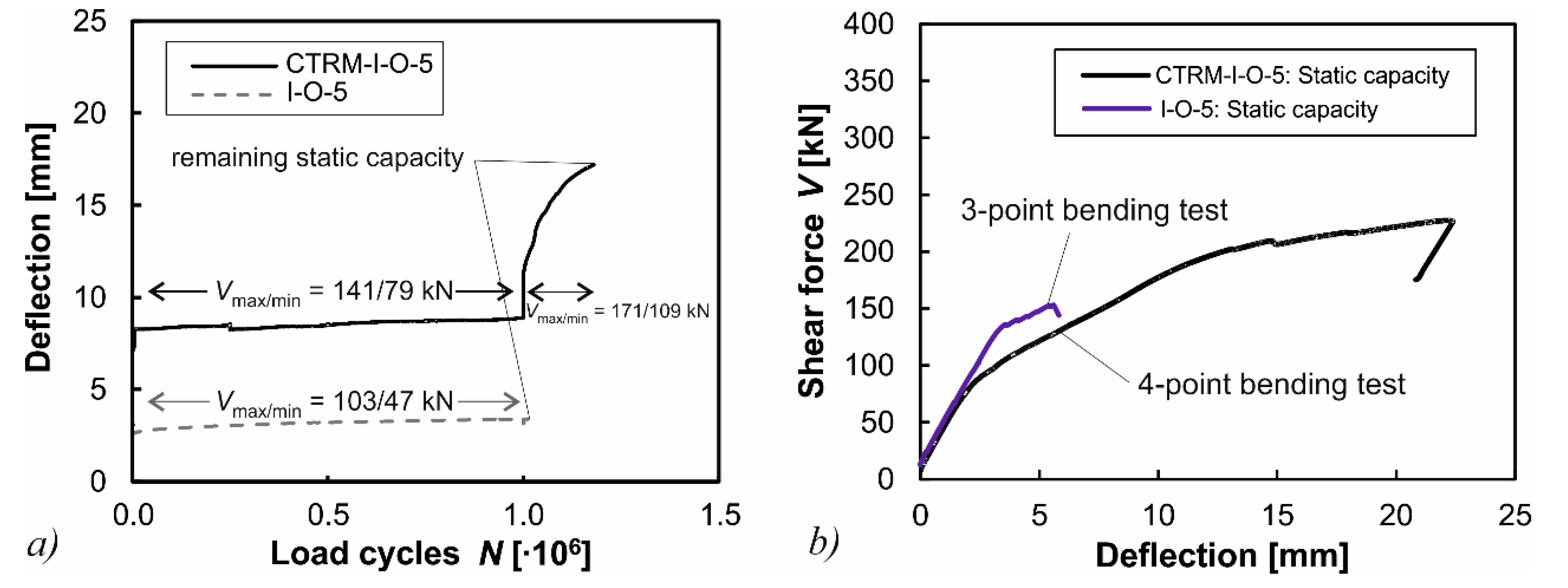
For the test beams without shear reinforcement (I-O-5 and CTRM-I-O-5) the highest load of the strengthened beam CTRM-I-O-5 was increased by 40% in comparison to the non-strengthened beam I-O-5. Nevertheless, the beam strengthened with CTRM did not show any signs of fatigue failure. In the following step, the loading was increased further so that the maximum load was almost equal to the initial shear crack load of the non-strengthened specimen I-O-5. At this level, the non-strengthened beam would have failed immediately, whereas the beam with CTRM sustained another 180,000 load cycles despite the formation of a large shear crack (Figure 11a). Although additional load cycles would have been possible, the testing was aborted at this point due to large deflections. The remaining static capacity of the specimen CTRM-I-O-5 was Vult = 233 kN, whereas the original specimen without CTRM had a remaining capacity of only Vult = 158 kN (Figure 11b).
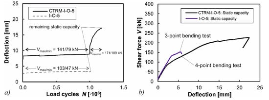
Figure 11.
(a) Comparison of vertical deflections under cyclic loading for tests without shear reinforcement; and (b) the comparison of the remaining shear capacities of non-strengthened and strengthened specimens.
3.5.3. Specimen CTRM-M-22-7
The stirrup strains of the specimens with shear reinforcement, which were measured by strain gauges, are shown in Figure 12 for specimens M-22-7 (without CTRM-strengthening) and CTRM-M-22-7. The peak load of the specimen CTRM-M-22-7 was increased by about 30% compared to the previous specimen M-22-7. In the previous experiment without CTRM-strengthening, various stirrups failed during the first 106 load cycles which can be seen from the progression of the curve in Figure 12a. In contrast, the beam strengthened with CTRM did not exhibit any damage on the stirrups after 2 × 10⁶ load cycles, after which the amplitude was increased further (Figure 12b). After the increase of the amplitude, some stirrups failed and the deflection grew moderately. Even then, the beam was able to sustain another 1.1 × 10⁶ load cycles after which the test was aborted. This behavior indicates a considerable load transfer over the CTRM strengthening, relieving the existing stirrups.

Figure 12.
Stirrup strains in the vicinity of the supports for (a) M-22-7; and (b) CTRM-M-22-7.
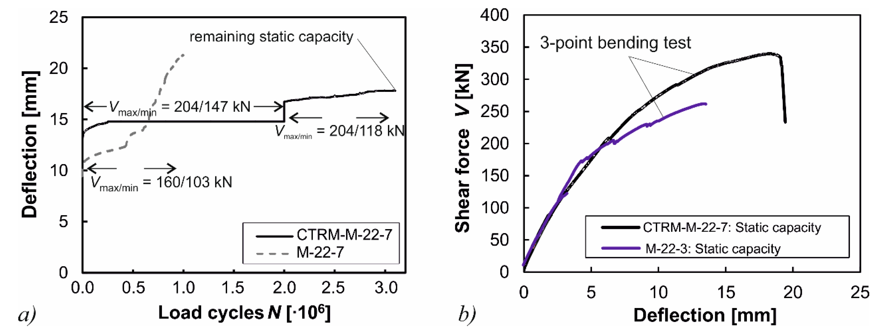
The deflections in dependence of the load cycles and the load-deflection curves under static loading are illustrated in Figure 13. The strong increase of the deflection of the non-strengthened beam M-22-7 indicates a progressive failure of stirrups during the first 106 load cycles (Figure 13a). On the other side, the strengthened specimen CTRM-M-22-7 did not show any signs of a progressive fatigue failure even after increasing the amplitude after 2.0 × 10⁶ load cycles. The remaining capacity of the beam CTRM-M-22-7 amounted to Vult = 350 kN (Figure 13b). The remaining capacity of the original beam M-22-7 was not determined due to its considerable damage in the stirrups. However, another previous test beam M-22-3 with the same pre-stressing, but subjected to smaller highest loads, had a remaining capacity of Vult = 264 kN. It can, therefore, be seen that the CTRM strengthening had a considerable effect on the remaining shear capacity for the beams with shear reinforcement as well.
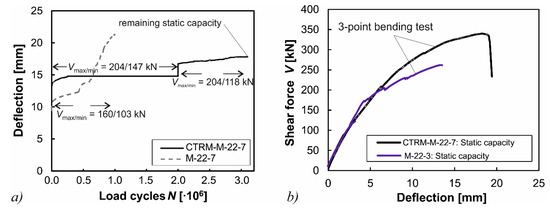
Figure 13.
(a) Comparison of vertical deflections under cyclic loading for tests with shear reinforcement; and (b) the comparison of the remaining shear capacities of the non-strengthened and strengthened specimens.
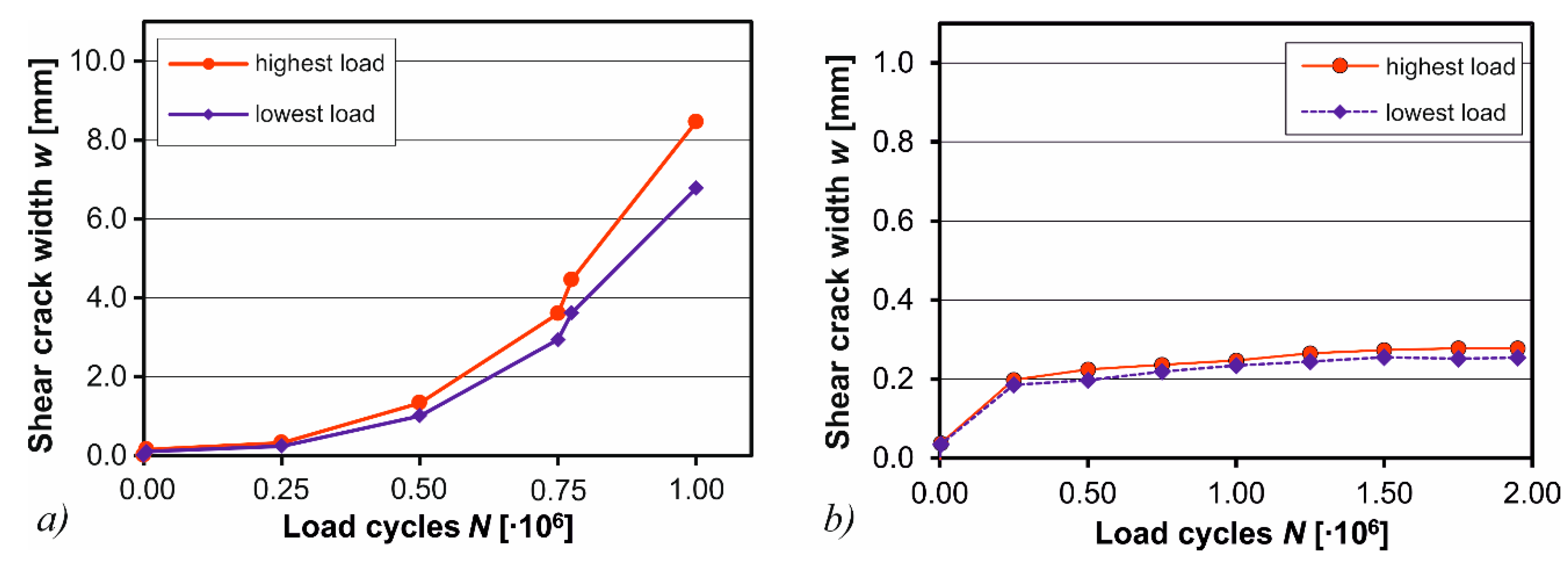
This is also indicated by the crack width measurements in the shear span made by digital image correlation (DIC). The DIC technique is frequently used in shear tests to accurately analyze the crack growth [50,51]. Here, the Aramis system (v5.4, GOM GmbH, Braunschweig, Germany) was used [52]. The shear crack widths for specimen M-22-7 dependent of the load cycles are illustrated in Figure 14a for highest and lowest loads. As can be seen, the shear crack widths increase rapidly to over 8 mm during the first 106 load cycles in correspondence with the failure of stirrups according to Figure 12a and the increase of deflections according to Figure 13a. For the strengthened specimen CTRM-M-22-7, the crack widths were measured during the first 2 × 10⁶ load cycles (Figure 14b). The diagram, which is scaled down by one order of magnitude compared to Figure 14a, shows that the shear crack widths are considerably smaller ranging from 0.2 to 0.3 mm. Additionally, the crack widths do not increase exponentially as for the non-strengthened specimen, which illustrates the stabilizing effect of the CTRM-strengthening.
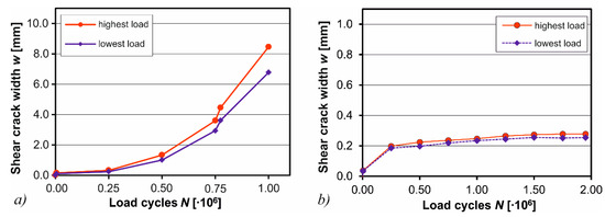
Figure 14.
Shear crack widths w according to digital image correlation for (a) M-22-7 and (b) CTRM-M-22-7.
3.5.4. Summary
The strengthening effect of textile-reinforced sprayed mortar on the webs of pre-stressed concrete beams was tested on two specimens under cyclic and fatigue loading. The test results were compared to similar beam tests without CTRM strengthening. In summary, the following conclusions can be drawn from the tests:
- Although the strengthening layer was not anchored in the compression or tension chord, a significant strengthening effect was observed. This effect can be explained by the contribution of the horizontal rovings which are activated at crack opening.
- For the specimen without shear reinforcement, additional 180,000 load cycles could be sustained after shear crack formation which results in a much more ductile behavior in comparison to non-strengthened specimens.
- For the specimen with shear reinforcement a significant reduction of stirrup strains was observed, as well as significantly smaller shear crack widths. By this, a progressive fatigue failure was prevented by the CTRM-strengthening.
- A bond failure between old concrete and strengthening layer could not be observed in any of the tests as the surface was sufficiently roughened and cleaned prior to strengthening. However, if the surface is not prepared according to the applicable standards [49], bond failure might occur, neutralizing a potential strengthening effect.
These tests have therefore shown, that there was a considerable increase of the fatigue and ultimate capacity of the strengthened beams, although the CTRM layer was not anchored in the compression or tension chord. Although, a general design method to predict the strength of members with a retroactive CTRM-strengthening cannot be derived based on these tests, the investigations indicate that a further investigation of this strengthening method might be quite promising for practical applications.
4. Conclusions
The use of carbon textile-reinforced mortar (CTRM) offers an innovative alternative for strengthening measures by combining the advantages of light, glued CFRP strips and the better bond characteristics of an additional concrete layer. Different fields of application were investigated and described in the paper: a considerable increase of the flexural strength and shear strength due to the CTRM-strengthening in the tension zone of bridge deck slabs was observed. Apart from the strengthening function, the CTRM layer can be used for real-time humidity monitoring and a preventive cathodic corrosion protection. These features potentially enable a significantly longer service life of the infrastructure due to the extended corrosion protection which is necessary, especially for the bridge deck surface.
A significant increase of the shear strength under static and cyclic loads was also obtained by strengthening the web of I-shaped profiles with a CTRM layer. Although the strengthening layer was not anchored in the chords of the test beams, the shear crack widths were reduced by a factor of 30 relieving the stirrups and, thus, enabling a very ductile behavior of the member. Within the scope of further experimental investigations, the strengthening method is to be optimized for use in practical applications. In addition to experimental investigations, theoretical investigations are required regarding practicable design models to realistically predict the strength of beams and slabs strengthened with CTRM.
Acknowledgments
Concerning the investigation of the CTRM strengthening of bridge webs the authors give thanks to the Federal Ministry for Economic Affairs and Energy for funding the project within the Central Innovation Programme for SMEs and to the company GQ Quadflieg Bau GmbH. The authors also give their thanks to the Federal Ministry of Education and Research (BMBF) for supporting the project Smart-Deck (support code: 13N12108) and to the VDI Technologiezentrum GmbH, which was consigned to the consulting and the implementation of the support guidelines by the BMBF, for the valuable assistance. Moreover, the authors gratefully acknowledge the project partners, the Federal Highway Research Institute (BASt), Eurovia Beton GmbH NL Bauwerksinstandsetzung, FTA Forschungsgesellschaft fuer Textiltechnik Albstadt mbH, in cooperation with Solidian GmbH, Massenberg GmbH, Sto Cretec GmbH, a subsidiary of Sto SE and Co. KGaA, and the Institute of Building Research, Building Materials, and Polymer Composites of RWTH Aachen University for the successful collaboration.
Author Contributions
Josef Hegger, Viviane Adam, and Martin Herbrand conceived and designed the experiments; Viviane Adam and Dominik Kueres performed the experiments on bridge deck slabs; Martin Herbrand and Martin Classen performed the experiments on pre-stressed concrete beams; and Viviane Adam, Martin Herbrand, Martin Classen, and Dominik Kueres analyzed the data and wrote the paper.
Conflicts of Interest
The authors declare no conflict of interest.
References
- BMVI. Strategie zur Ertuechtigung der Strassenbruecken im Bestand der Bundesfernstrassen; German Federal Ministry of Transport and Digital Infrastructure: Berlin, Germany, 22 May 2013.
- Naumann, J. Bridges and heavy goods traffic—An inventory. Bauingenieur 2010, 85, 1–9. [Google Scholar]
- Freundt, U.; Böning, S.; Kaschner, R. Road bridges between actual and future heavy load traffic-Road traffic loads according to DIN EN 1991-2/NA. Beton Stahlbetonbau 2011, 106, 736–746. [Google Scholar] [CrossRef]
- Ickert, L.; Matthes, U.; Rommerskirchen, S.; Weyand, E.; Schlesinger, M.; Limbers, J. Abschaetzung der langfristigen Entwicklung des Gueterverkehrs in Deutschland bis 2050; Project for the BMVI, Report: 26.0185/2006; BMVI: Basel, Switzerland, 31 May 2007. [Google Scholar]
- Naumann, J. Bridges and heavy goods vehicle traffic—A strategy for strengthening existing bridges on federal trunk roads. Bauingenieur 2010, 85, 210–216. [Google Scholar]
- Curbach, M.; Garibaldi, M.P.; Steinbock, O. Dealing with the bridge inventory—A comparison between Germany and the USA. Bauingenieur 2016, 91, 215–226. [Google Scholar]
- Chen, W.; Xie, Z.; Yan, B. Research on the general method for extrapolating traffic load effects for highway bridges. Stahlbau 2014, 83, 186–198. [Google Scholar] [CrossRef]
- Lantsoght, E.O.L.; van der Veen, C.; Walraven, J.C.; de Boer, A. Recommendations for the shear assessment of reinforced concrete slab bridges from experiments. Struct. Eng. Int. 2013, 23, 418–426. [Google Scholar] [CrossRef]
- Schellenberg, K.; Vogel, T.; Chèvre, M.; Alvarez, M. Assessment of bridges on the Swiss national roads. Struct. Eng. Int. 2013, 4, 402–410. [Google Scholar] [CrossRef]
- Fischer, O.; Müller, A.; Lechner, T.; Wild, M.; Kessner, K. Findings and insights concerning the results of re-analyzed concrete bridges in Germany. Beton Stahlbetonbau 2014, 109, 107–127. [Google Scholar] [CrossRef]
- Hegger, J.; Herbrand, M.; Stark, A.; Classen, M. The future of structural concrete: Light, filigree and sustainable. Bauingenieur 2015, 90, 337–344. [Google Scholar]
- Teworte, F.; Herbrand, M. Structural shear assessment of an existing concrete bridge under static and fatigue loading. Bauingenieur 2014, 89, 531–536. [Google Scholar]
- Hegger, J.; Marzahn, G.; Teworte, F.; Herbrand, M. Principal tensile stress criterion for the shear assessment of existing concrete bridges. Beton Stahlbetonbau 2015, 110, 82–95. [Google Scholar] [CrossRef]
- Herbrand, M.; Classen, M. Shear tests on continuous pre-stressed concrete beams with external prestressing. Struct. Concr. 2015, 16, 428–437. [Google Scholar] [CrossRef]
- Teworte, F.; Herbrand, M.; Hegger, J. Structural assessment of concrete bridges in Germany-Shear resistance under static and fatigue loading. Struct. Eng. Int. 2015, 25, 266–274. [Google Scholar] [CrossRef]
- Hegger, J.; Maurer, R.; Zilch, K.; Herbrand, M.; Kolodzieiczyk, A.; Dunkelberg, D. Assessment of the shear capacity of existing prestressed concrete bridge girders. Bauingenieur 2014, 89, 500–509. [Google Scholar]
- Herbrand, M. Shear Strength Models for Reinforced and Prestressed Concrete Members. Ph.D. Thesis, RWTH Aachen University, Aachen, Germany, 9 June 2017. [Google Scholar]
- Herbrand, M.; Kueres, D.; Classen, M.; Hegger, J. Uniform shear design method for existing reinforced and prestressed concrete bridges. Beton Stahlbetonbau 2016, 111, 58–67. [Google Scholar] [CrossRef]
- Herbrand, M.; Classen, M.; Stark, A.; Kueres, D. Uniform shear design method for existing reinforced and pre-stressed concrete bridges–extended background. Bauingenieur 2016, 91, 487–495. [Google Scholar]
- Welsch, T.; Reissen, K.; Schnellenbach-Held, M.; Hegger, J.; von Weschpfennig, D.; Haardt, P. Experiences on the strengthening of concrete bridges. Beton Stahlbetonbau 2016, 111, 241–252. [Google Scholar] [CrossRef]
- Haveresch, K.H. Checking and strengthening older pre-stressed concrete bridges. Beton Stahlbetonbau 2011, 106, 89–102. [Google Scholar] [CrossRef]
- Herbrand, M.; Hegger, J. Experimental investigations on the influence of an external prestressing on the shear capacity of pre-stressed continuous beams. Bauingenieur 2013, 88, 509–517. [Google Scholar]
- Hegger, J.; Voss, S. Investigation of the load-bearing behavior and potential of textile-reinforced concrete. Eng. Struct. 2008, 30, 2050–2056. [Google Scholar] [CrossRef]
- Hegger, J.; Horstmann, M.; Voss, S.; Will, N. Textile-reinforced concrete load-bearing behaviour, design and application. Beton Stahlbetonbau 2007, 102, 362–370. [Google Scholar] [CrossRef]
- Hegger, J.; Will, N.; Bruckermann, O.; Voss, S. Load-bearing behaviour and simulation of textile-reinforced concrete. Mater. Struct. 2006, 39, 765–776. [Google Scholar] [CrossRef]
- Shams, A.; Hegger, J.; Horstmann, M. An analytical model for sandwich panels made of textile-reinforced concrete. Constr. Build. Mater. 2014, 64, 451–459. [Google Scholar] [CrossRef]
- Kulas, C.; Rempel, S. Bending bearing behavior of impregnated textile reinforcement for concrete elements. Bauingenieur 2015, 90, 248–251. [Google Scholar]
- Tietze, M.; Kahnt, A.; Schladitz, F.; Scheerer, S.; Curbach, M. C3—Carbon reinforced concrete construction of the future. In Proceedings of the fib Symposium, Copenhagen, Denmark, 18 May 2015. [Google Scholar]
- Hegger, J.; Kulas, C.; Raupach, M.; Büttner, T. Load-Bearing behavior and durability of a slender textile-reinforced concrete bridge. Beton Stahlbetonbau 2011, 106, 72–80. [Google Scholar] [CrossRef]
- Scholzen, A.; Chudoba, R.; Hegger, J. Thin-walled shell structure made of textile-reinforced concrete: Design, dimensioning and realization. Beton Stahlbetonbau 2012, 107, 767–775. [Google Scholar] [CrossRef]
- Kromoser, B.; Ritt, M. Optimized shapes for textile-reinforced concrete structures. Bauingenieur 2016, 91, 425–433. [Google Scholar]
- Horstmann, M.; Hegger, J. Sandwich facades made of textile-reinforced concrete-experimental investigations. Bautechnik 2011, 88, 281–291. [Google Scholar] [CrossRef]
- Scholzen, A.; Chudoba, R.; Hegger, J. Thin-walled shell structures made of textile-reinforced concrete, Part I: Structural design and construction. Struct. Concr. 2015, 16, 106–114. [Google Scholar] [CrossRef]
- Scholzen, A.; Chudoba, R.; Hegger, J. Thin-walled shell structures made of textile-reinforced concrete, Part II: Experimental characterization, ultimate limit state assessment and numerical simulation. Struct. Concr. 2015, 16, 115–124. [Google Scholar] [CrossRef]
- Rempel, S.; Will, N.; Hegger, J.; Beul, P. Filigree textile-reinforced concrete constructions performance and potential application of innovative composite material. Beton Stahlbetonbau 2015, 110, 83–93. [Google Scholar] [CrossRef]
- Brückner, A.; Ortlepp, R.; Curbach, M. Textile-reinforced concrete for strengthening in bending and shear. Mater. Struct. 2006, 39, 741–748. [Google Scholar] [CrossRef]
- Brückner, A.; Ortlepp, R.; Curbach, M. Anchoring of shear strengthening for T-beams made of TRC. Mater. Struct. 2008, 41, 407–418. [Google Scholar] [CrossRef]
- Barhum, R.; Büllesbach, J.; Müller, A. Textile-reinforced concrete for repair of a balcony panels made of reinforced concrete. Bauingenieur 2015, 90, 241–247. [Google Scholar]
- Erhard, E.; Weiland, S.; Lorenz, E.; Schladitz, F.; Beckmann, B.; Curbach, M. Applications of textile-reinforced concrete strengthening. Beton Stahlbetonbau 2015, 110, 74–82. [Google Scholar] [CrossRef]
- Herbrand, M.; Classen, M.; Hegger, J. Shear tests on pre-stressed concrete beams strengthened with carbon textile-reinforced spray mortar under cyclic loading. Beton Stahlbetonbau 2016, 109, 576–587. [Google Scholar] [CrossRef]
- Herbrand, M.; Adam, V.; Hegger, J. Investigations on the strengthening of existing highway bridges under shear and flexural loading with textile-reinforced Mortar. In Proceedings of the fib Symposium, Maastricht, The Netherlands, 14 June 2017. [Google Scholar]
- Brückner, A.; Wellner, S.; Ortlepp, R.; Scheerer, S.; Curbach, M. T-beams strengthened with TRC under non predominantly static loading. Beton Stahlbetonbau 2013, 108, 169–178. [Google Scholar] [CrossRef]
- Solidian GmbH. Available online: https://www.solidian.com/en/ (accessed on 11 September 2017).
- Eurocode 1: Actions on Structures–Part 2: Traffic Loads on Bridges; EN 1991-2; CEN European Committee for Standardisation: Brussels, Belgium, 2010.
- Fisker, J.; Hagsten, L.G. Mechanical model for the shear capacity of R/C beams without stirrups: A proposal based on limit analysis. Eng. Struct. 2016, 115, 220–231. [Google Scholar] [CrossRef]
- Lorenz, E.; Schütze, E.; Schladitz, F.; Curbach, M. Textile-reinforced concrete–Overview of standard test methods. Beton Stahlbetonbau 2013, 108, 711–722. [Google Scholar] [CrossRef]
- Teworte, F.; Hegger, J. Fatigue of prestressed beams without web reinforcement under cyclic shear. Beton Stahlbetonbau 2013, 108, 34–46. [Google Scholar] [CrossRef]
- Teworte, F.; Hegger, J. Fatigue of prestressed beams with web reinforcement under cyclic shear. Beton Stahlbetonbau 2013, 108, 475–486. [Google Scholar] [CrossRef]
- Momber, A.W.; Schulz, R.R. Handbuch der Oberflächenbearbeitung Beton; Birkhäuser Verlag: Basel, Switzerland, 2006; ISBN 978-3-7643-6218-8. [Google Scholar]
- Hegger, J.; Sherif, A.; Görtz, S. Investigation of pre- and postcracking shear behavior of pre-stressed concrete beams using innovative measuring techniques. ACI Struct. J. 2004, 101, 183–192. [Google Scholar]
- Herbrand, M.; Classen, M.; Adam, V. Shear tests on pre-stressed concrete continuous beams with rectangular and I-shaped cross-sections. Bauingenieur 2017, 92. [Google Scholar] [CrossRef]
- Aramis, version 5.4; User Information Manual; GOM GmbH: Braunschweig, Germany, 2005.
© 2017 by the authors. Licensee MDPI, Basel, Switzerland. This article is an open access article distributed under the terms and conditions of the Creative Commons Attribution (CC BY) license (http://creativecommons.org/licenses/by/4.0/).

