1. Introduction
Contact between surfaces plays a very important role in the industry field [
1]. Coatings have been widely applied on the contact surfaces [
2,
3,
4], since it is an effective means to improve the mechanical performance such as the wear resistance, corrosion resistance and so on, where tribological performance should be specially considered among them. To select optimal coatings efficiently and achieve best tribology performance for different substrate materials is very meaningful but full of challenges. Until now, the trial and error method is still the usual approach since there seems to be little effective and perfect theories to guide to achieve the coating optimization, as the authors know. Therefore, to develop the related theory should be the direction which guides the efforts going forward.
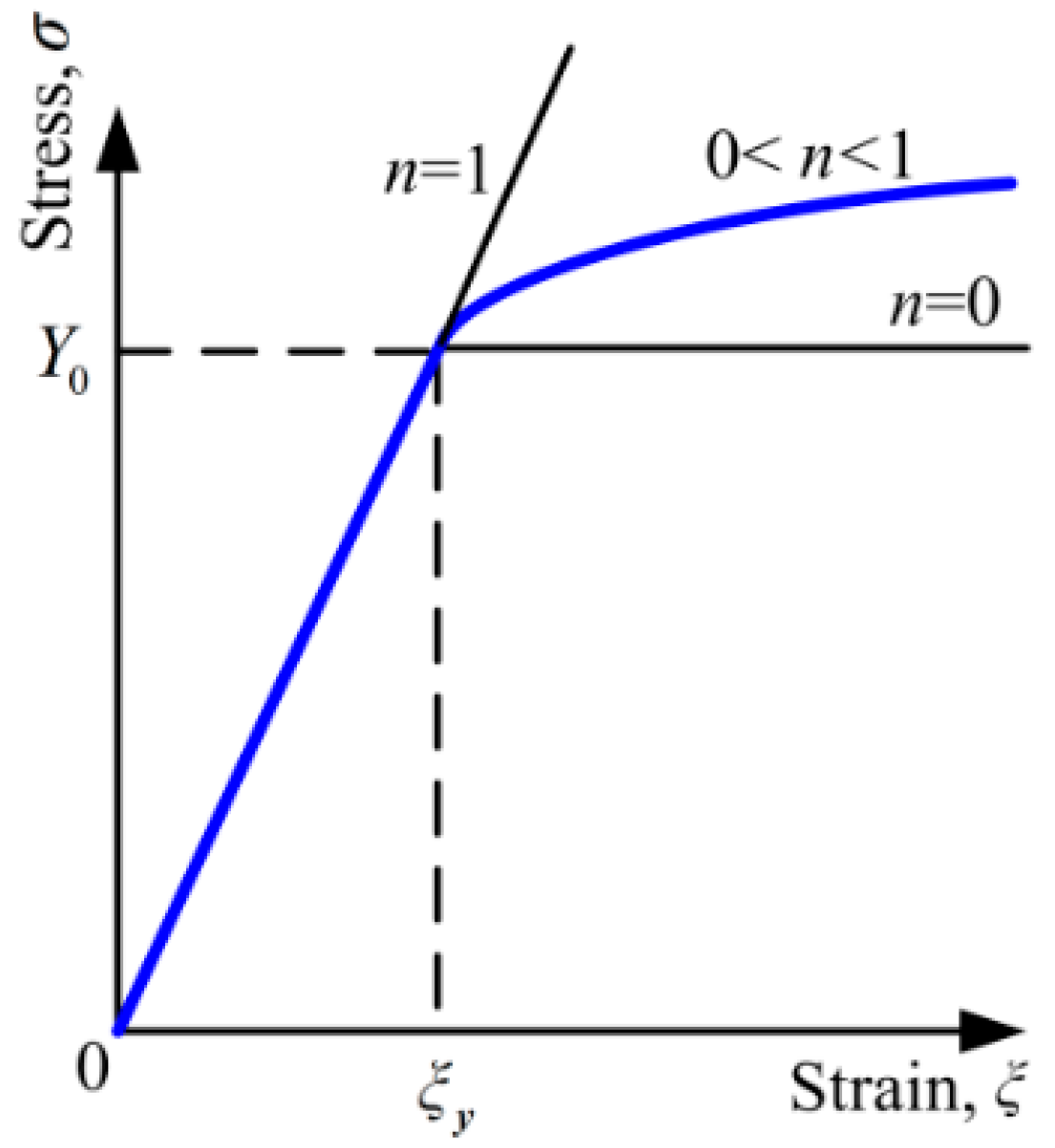
All contact surfaces are rough on the microscale and contain many asperities. When two coating surfaces are in contact with each other, the contact happens at the top of the coated asperity in fact. Therefore, the contact between coated asperities should be the first problem to be considered, which is always simplified as the contact between a sphere and a flat [
5]. Generally, when an asperity and a flat contact with each other, the asperity could be flattened by the flat or indent it [
6]. Most studies about the coating contact so far considered the indentation, i.e., a rigid spherical indenter contact with a coated deformable flat, since they focused on the mechanical properties of the coating. Pogrebnjak [
7] studied the structural and mechanical properties of NbN and Nb–Si–N films with the experimental method and the molecular dynamics simulation. Coy et al. [
8] considered the topographic reconstruction and mechanical properties of atomic layer deposited Al
2O
3/TiO
2 nanolaminates by nanoindentation. However, when the tribological performance is the focus of attention, the flattening that is associated with mild adhesive friction and wear should be considered. In this work, the flattening process of the coated asperity by a rigid flat is explored.
Chang [
9] developed a modified elastic–plastic asperity contact model on basis of Greenwood–Williamson (GW) model [
10] to study the contact between surfaces with soft coatings. The effect of the coating thickness and plasticity index on the contact area and normal load was investigated. McCool [
11] described a micro-contact model by extending the GW model [
10] to investigate the coating contact, and explored the effect of the coating thickness and compliance on the contact load, area and mean real pressure. Liu et al. [
12] presented extended Hertzian formulae to predict contact behaviors for circular and elliptical point contact problems with the presence of coating. They expressed the extended equivalent modulus of the coated asperity as the function of the coating thickness along with Young’s modulus and Poisson’s ratio of the coating and the substrate. Garjonis et al. [
13] presented the analytical and finite element (FE) models by means of Hertz theory and FE methods respectively, to study the normal contact between two layered spheres in the elastic phase. They obtained the force-displacement relation in the process of contact between the layered asperities, and validated these relations by FE results. Yeo et al. [
14] used an improved elastic contact model to investigate the contact between a coated asperity and a rigid flat, and to study the asperity contact stiffness. The results were also verified by the FE results. Goltsberg and Etsion [
15] used the FE method to explore the elastic contact between a coated asperity and a rigid flat. They studied the effect of the geometrical and mechanical properties of the coating and substrate on contact behaviors, and got universal dimensionless formulae about the relation of load and displacement based on many simulation results. Subsequently, Goltsberg and Etsion [
16] continued to study the contact area and maximum equivalent stress using the FE method and obtained the corresponding dimensionless expressions, constituting a complete universal contact model for the elastic coated asperity contact along with their previous work presented in [
15].
All these models about the coated asperity contact introduced above considered the elastic case, i.e., both the substrate and the coating were assumed as the purely elastic materials. However, for many metallic materials, their stress-strain relations actually show elastic–plastic characteristics. Therefore, it should be necessary to consider the behavior of the elastic–plastic asperity contact. Eid et al. [
17] proposed a coated asperity contact model considering the effect of adhesion. The material properties of the asperity including the substrate and coating are both assumed to be elastic–plastic with 2% linear hardening of the elastic modulus. The effect of the coating thickness on the pull-off force and contact radius in the loading and unloading processes was studied. Goltsberg et al. [
18] investigated the onset of the plastic yielding in a coated sphere when it contacted with a rigid flat by means of the FE software. The asperity materials were also assumed as elastic–plastic with 2% linear hardening of the elastic modulus. The influence of the asperity material properties and the coating thickness on the critical contact parameters was investigated, such as critical normal load, area and interference when the plastic yielding first appears. Chen et al. [
19] continued to study the plasticity evolution in the coated asperity which is 2% linear hardening elastic–plastic material during the process of contact with a rigid flat, and obtained empirical expressions about the critical interferences at the onset of plastic yielding. In addition, they found that as the interference increased, the elastic core (low-stress zone) appeared under the contact area, leading to the decrease of the mean pressure.
Most of the FE models mentioned above about the coated asperity contact focused on the elastic or 2% linear hardening elastic–plastic asperity materials. However, for many materials, the power law is more precise to describe their strain hardening behavior [
20]. The influence of the power-law hardening material properties on the coated asperity contact has not been studied in detail, which will be considered in this work where the substrate is set as the power law hardening elastic–plastic materials. Then, the effect of the substrate-hardening exponent on the contact parameters such as contact load, area and stress is focused on in this work. On basis of the numerical analysis in this work, the effect of the material property and geometrical characteristics of coating/substrate system on its tribological performance could be predicted preliminarily and accurately in the future, and then it would be meaningful to help choose the optimal coating and obtain the best tribological performance. It should be noted that this work focuses on the very hard coating such as diamond-like carbon (DLC) film, which could be simplified and assumed as the purely elastic materials as revealed in Refs. [
15,
16].
3. Results and Discussion
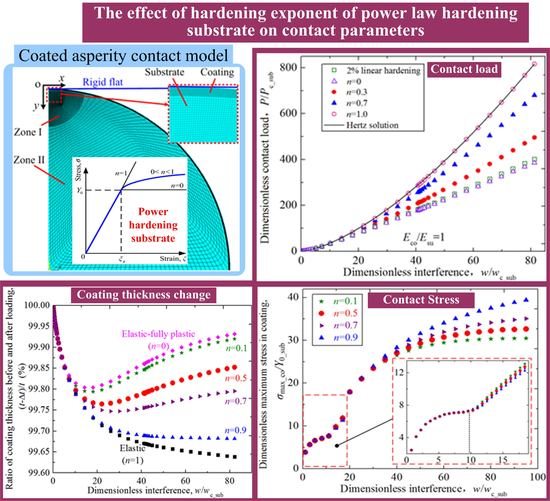
The results about the contact behaviors obtained with the developed FE model are shown in this section. The geometrical and material parameters for the coated asperity are set as follows: The asperity radius R changes from 5 mm to 20 mm; the dimensionless coating thickness t/R varies in the range of 0.001 ≤ t/R ≤ 0.02 with the interval of 0.001; the Poisson’s ratios of the coating νco and the substrate νsu are both set as 0.32, a common value for metallic materials; the Young’s modulus of the coating Eco and the substrate Esu changes in a wide range of 1 ≤ Eco/Esu ≤ 10; the yield strength of the substrate Y0_sub is assumed as a constant 210 MPa; the hardening exponent of the substrate n ranges from 0 to 1. The geometrical and material parameters could be chosen arbitrarily from the range mentioned above, covering a large number of realistic materials to consider the effect of the substrate hardening exponent on the contact behaviors. Some typical cases are selected and shown as follows based on the condition that asperity radius R is 10 mm.
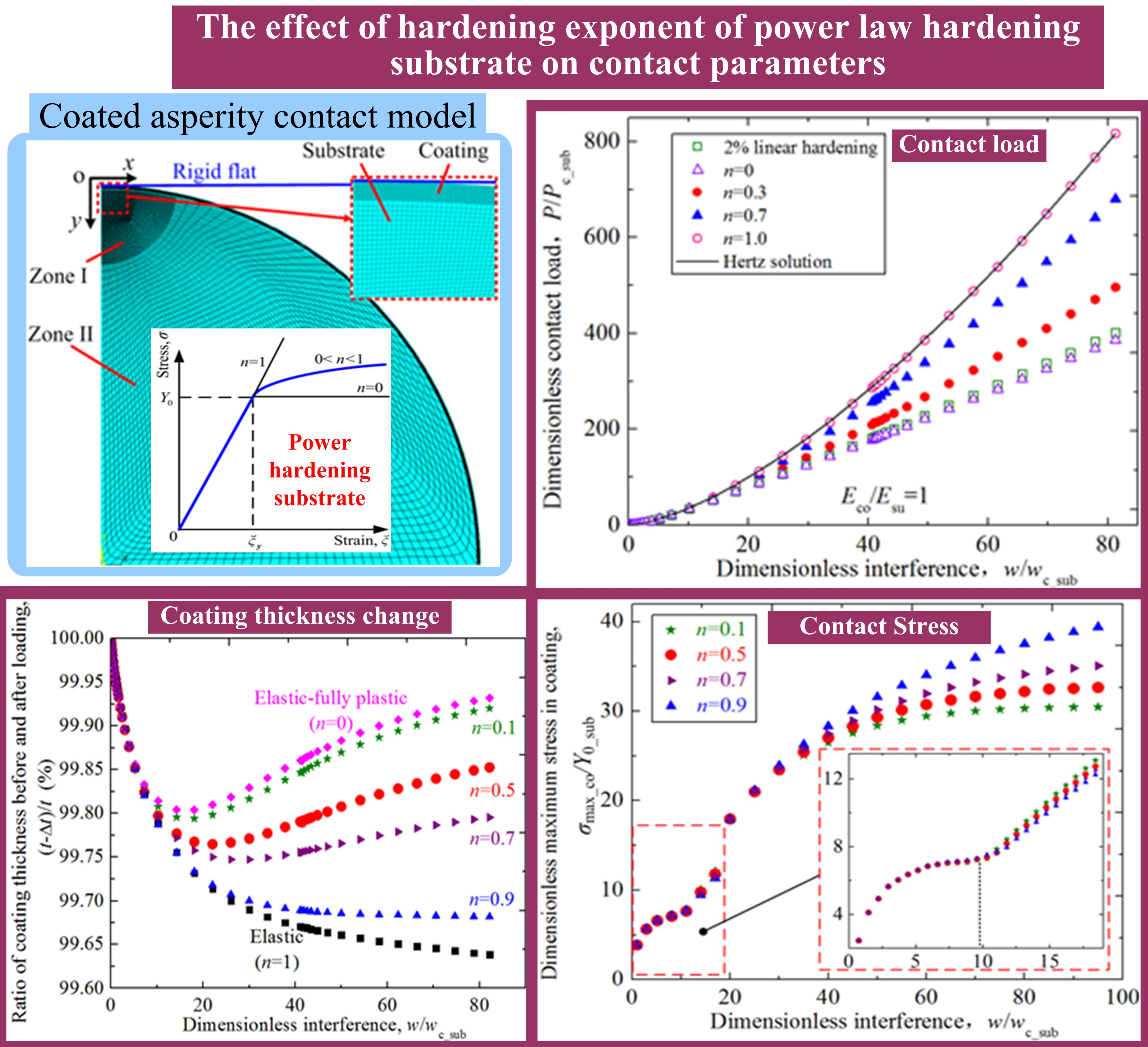
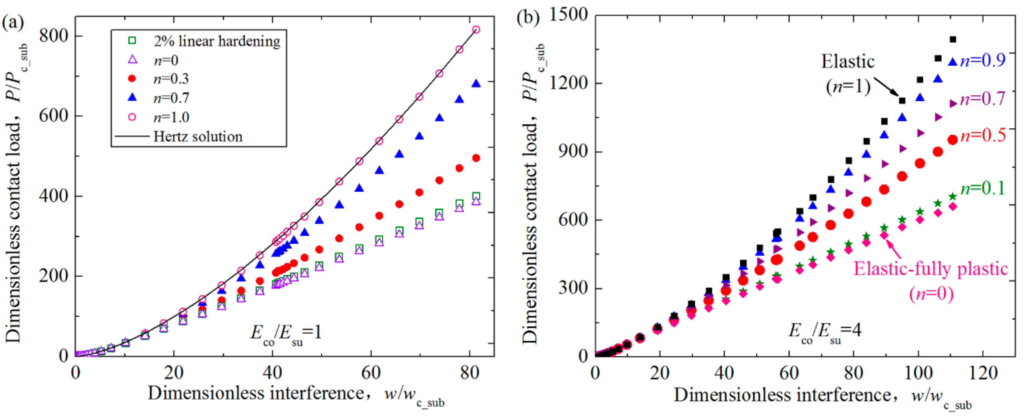
Figure 3 presents the influence of hardening exponents of the substrate
n on the relation between the dimensionless contact load
P/
Pc_sub and interference
w/
wc_sub for the contact between a rigid flat and a coated asperity having the power law hardening elastic–plastic substrate. Some typical results are selected to be shown for the cases where the hardening exponent of the substrate
n ranges from 0 to 1 at two selected Young’s modulus ratios
Eco/
Esu = 1, 4. The dimensionless coating thickness
t/
R is set as 0.01. The critical contact area, load and interference of the substrate,
Ac_sub,
Pc_sub and
wc_sub, at the yielding inception under the normal load were given by Jackson and Green [
21]:
where
Esu and
Y0_sub is the Young’s modulus and yield strength of the substrate,
Cν is a parameter related to the Poisson’s ratio as
.
Figure 3a shows the results of the contact load for
Eco/
Esu = 1. Two extreme cases are also given as a comparison. One is the case of the substrate hardening exponent
n = 1.0, which means the asperity transforms into the homogenous and purely elastic material. In this case, the contact load is calculated and compared with the Hertz solution. The differences are less than 2.8% as stated in
Section 2. The other extreme case is that
n = 0, which means the substrate changes to be the elastic perfectly-plastic material. The numerical results for 2% linear hardening substrate case are also shown in
Figure 3a, to simulate the elastic perfectly-plastic material under the small interference considering its stress-strain relation as revealed in Ref. [
22]. The results show a good coincidence besides a small difference. The difference gets larger as the interference increases. This is due to the reason that the difference of material properties between the real 2% linear hardening elastic–plastic material and the ideal elastic perfectly–plastic material gets larger. The comparison for these two extreme cases proves that the FE model is accurate and can be used to consider the contact behavior under other conditions.
Figure 3b shows the results for
Eco/
Esu = 4. The elastic (
n = 1) and elastic fully-plastic (
n = 0) substrate of the asperity are also considered, which appears at two sides of the different exponent cases (0 <
n < 1). This also can prove the accuracy of this model to some extent. The curves in
Figure 3 reveal that the load increases with the increase of interferences. In addition, for the same Young’s modulus ratio case, the load becomes larger as the hardening exponent increases from 0 to 1 at a given interference. This is because as the hardening exponent increases, the substrate becomes more elastic, which means the reaction force of the asperity is larger under the same interference.
The contact area plays a very important role in the tribological behaviors such as wear, friction and so on, and thus the effect of the hardening exponent of the substrate on the contact area of the coated asperity are also studied in this work.
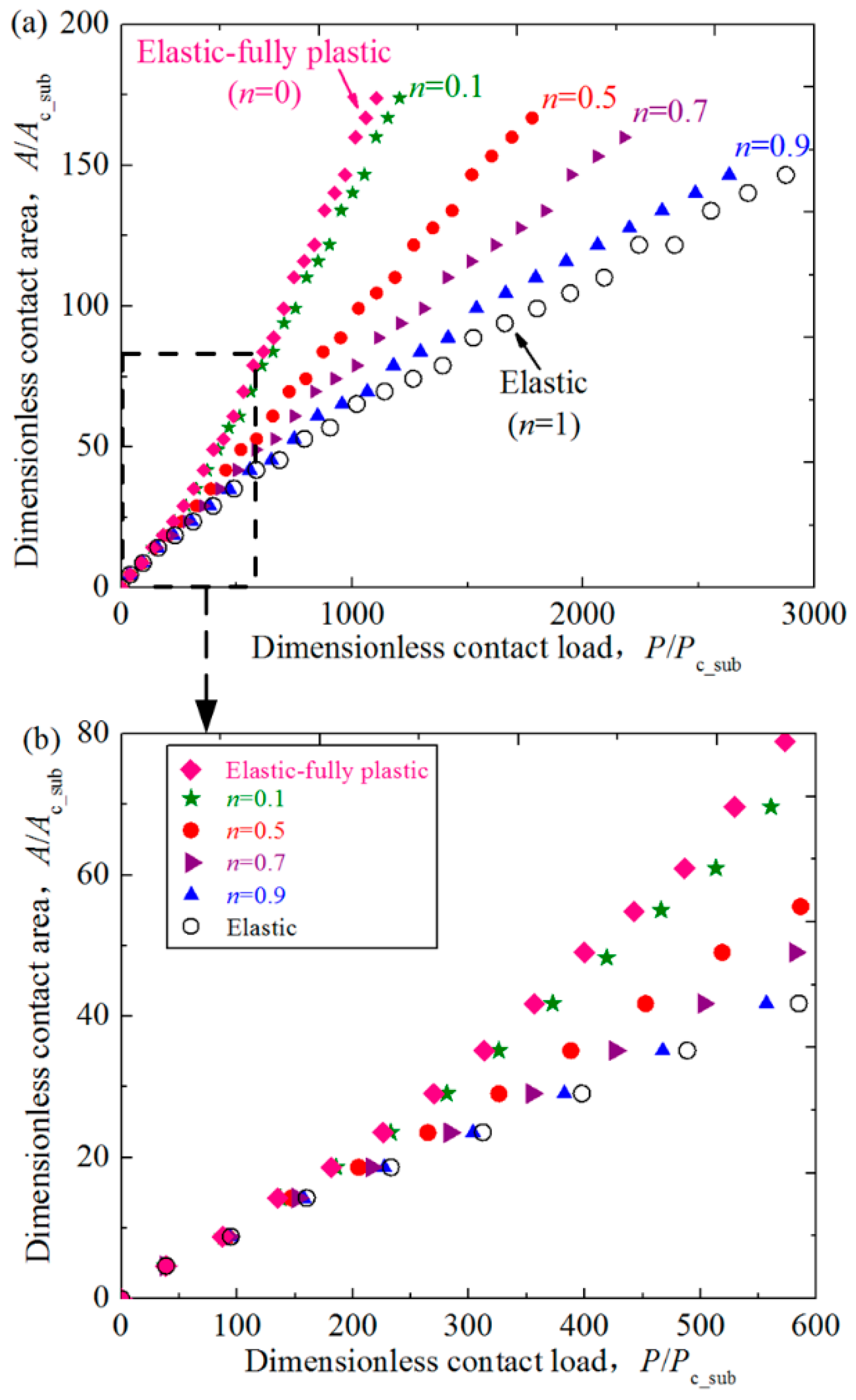
Figure 4 shows the relation between the dimensionless contact area
A/
Ac_sub and load
P/
Pc_sub for some typical cases where dimensionless coating thickness
t/
R = 0.01, Young’s modulus ratios
Eco/
Esu = 4 at some selected hardening exponents of the substrate
n = 0.1, 0.5, 0.7 and 0.9. In addition, the cases for the purely elastic (
n = 1) and elastic fully-plastic (
n = 0) substrate are also considered and shown in
Figure 4. It could be seen that the contact area increases as the value of
n decreases at a specific contact load. It is because the substrate with smaller
n is more plastic, and the same contact load will lead to larger interferences. Thus the contact area increases accordingly. This tendency can also be seen from
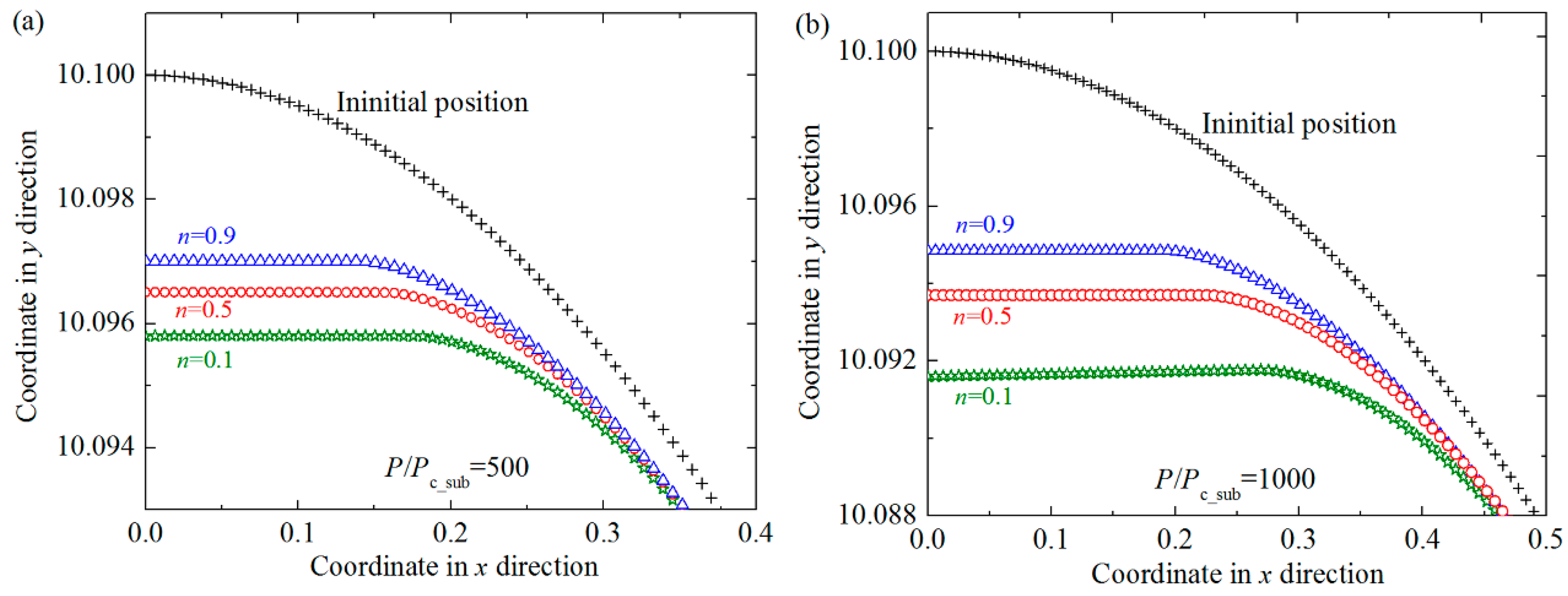
Figure 5, where the change of the profiles of the asperities with different substrate materials before and after the normal loading is given. The contact radii are shown as the flat parts in the center of the profiles, which also represents the size of the contact area. It could also be found that as the hardening exponent of the substrate
n decreases, the contact radii become larger, which accords with the conclusions given in
Figure 4.
The effect of the Young’s modulus ratios and coating thicknesses on the dimensionless contact behaviors was already considered in detail for the purely elastic or 2% linear hardening elastic–plastic asperity materials in the existing studies [
15,
16,
19], and the corresponding variation trend has been gotten for these materials. While for the power-law hardening substrate considered in this work, the trend should be verified. Therefore, the effect of the Young’s modulus ratios and dimensionless coating thicknesses on the dimensionless contact load
P/Pc_sub and area
A/Ac_sub are investigated, and the results for some typical cases where the typical hardening exponents
n = 0.1 and 0.9 are revealed in
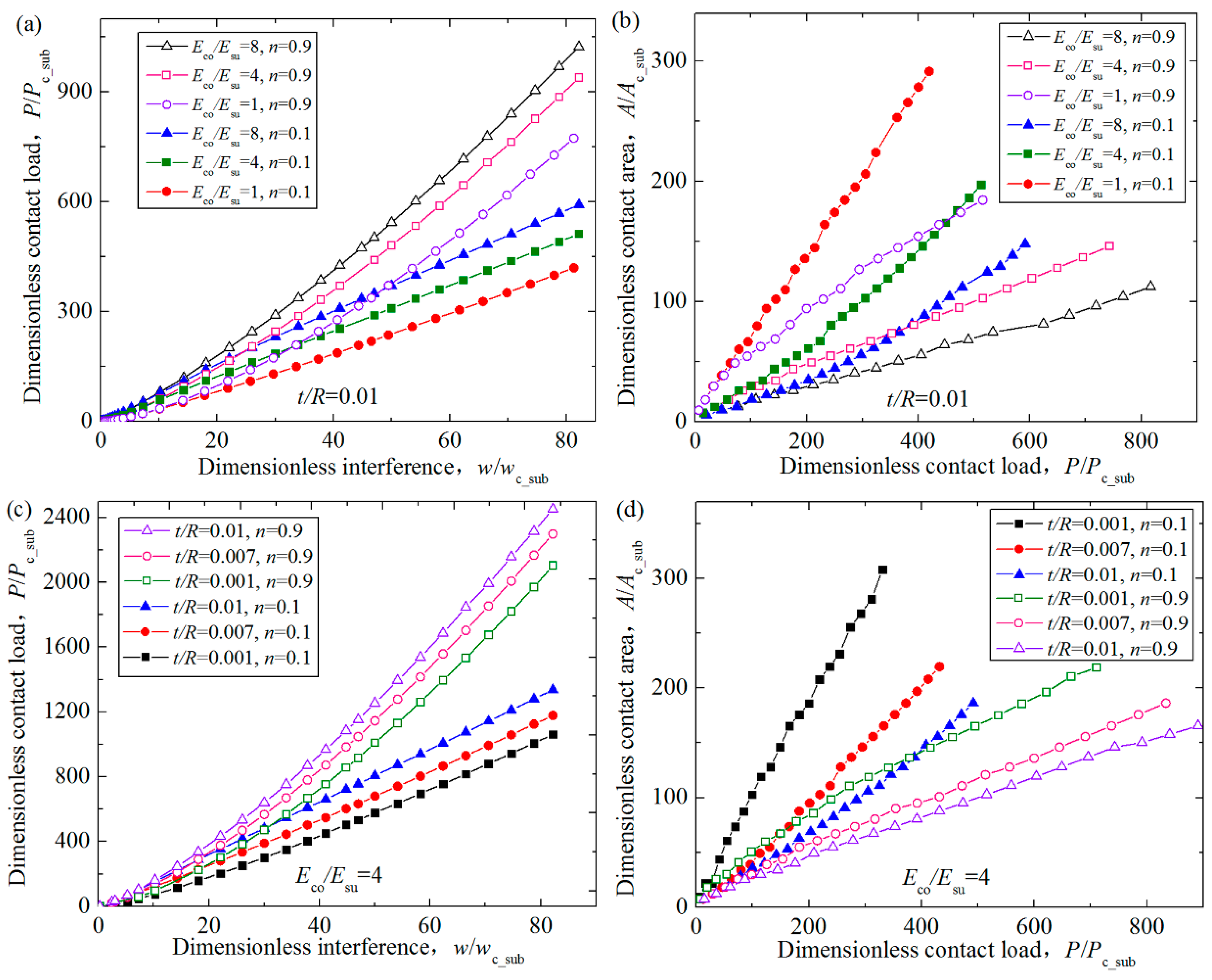
Figure 6.
Figure 6a,b shows that the variation of contact parameters for the cases where the Young’s modulus ratios
Eco/Esu = 1, 4, 8 when the dimensionless coating thickness
t/R = 0.01. It could be seen that for the coated asperity having a given
n value, the contact load increases as the
Eco/Esu value increases at a given interference. In other words, the interferences were larger for the coating system with smaller
Eco/
Esu values to get the same contact load. It means this kind of coating system has higher load bearing capacity to resist plowing, which will lead to smaller friction coefficient. This could help explain the experimental results shown in
Figure 2 in Ref. [
23], where the TiN(coating)/WC-Co(substrate) system presented a lower friction coefficient in the running-in stage since it had the lower elastic modulus ratio
Eco/
Esu than the TiN(coating)/Cu(substrate) system [
23]. While at a given contact load, the contact area decreases with the increase of the
Eco/Esu values. This trend is in accord with the conclusions given in Ref. [
16].
Figure 6c,d show the effect of the dimensionless coating thickness
t/R on the contact parameters. Some typical dimensionless coating thicknesses
t/R = 0.001, 0.007, 0.01, spanning an order of magnitude, are considered for the Young’s modulus ratios
Eco/Esu = 4. As shown in
Figure 6c,d, the contact load increases as the coating thickness becomes larger when the substrates are the same material. It is expected because the coating is harder and more elastic than the substrate, and the same interference will lead to larger contact load for the asperity with larger coating thickness. The contact area decreases with the increase of the coating thickness. It is probably because the same contact load will leads to less yielding for the asperities with the thicker coating. These results above accord with the conclusions given in Ref. [
15].
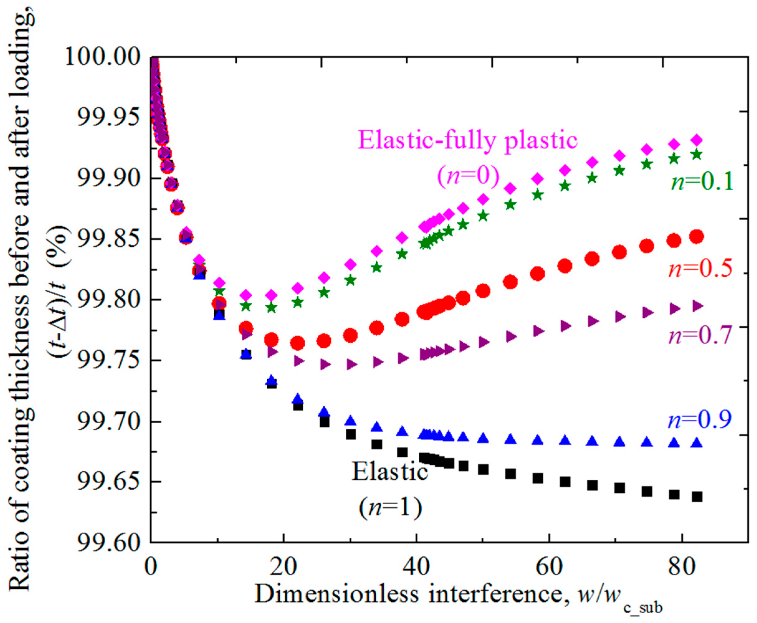
The effect of the hardening exponent of substrate on the change of the coating thickness during the normal loading process is studied.
Figure 7 shows the ratio of coating thickness before and after loading, (
t − Δ
t)/
t, changes with the dimensionless interference
w/wc_sub for different hardening exponent
n = 0.1, 0.5, 0.7, 0.9 cases. The decrease of the coating thickness on the axis of symmetry Δ
t could be calculated as the difference value between the interference of rigid flat
w and the axial displacement of the interface point on the axis of symmetry
wsub, i.e., Δ
t =
w − wsub. The elastic (
n = 1) and elastic fully-plastic (
n = 0) cases are also considered. The dimensionless coating thickness
t/R are set as 0.01 and Young’s modulus ratios
Eco/Esu = 4. It could be seen from
Figure 7 that for the asperity with the elastic substrate (
n = 1) or with the substrate whose hardening exponents are large and close to 1 (such as
n = 0.9), the coating thickness becomes smaller monotonically as the interference increases in the loading process. For these cases, the rate of the variation of coating thickness (absolute value) is very large at the very beginning of the contact, and then decreases gradually as the interference increases until it approaches zero (see the case
n = 0.9 in
Figure 7). While for the asperity with the substrate whose hardening exponents are smaller (such as
n ≤ 0.7), the coating thickness also reduces considerably in the early contact stage until reaches a minimum value, then it recovers gradually. For smaller hardening exponent cases, the transition point appears earlier and the recovery of the thickness is more obvious and rapid. Especially for the small
n cases such as
n = 0 and 0.1, the coating thickness can recover to 99.9% of the initial value.
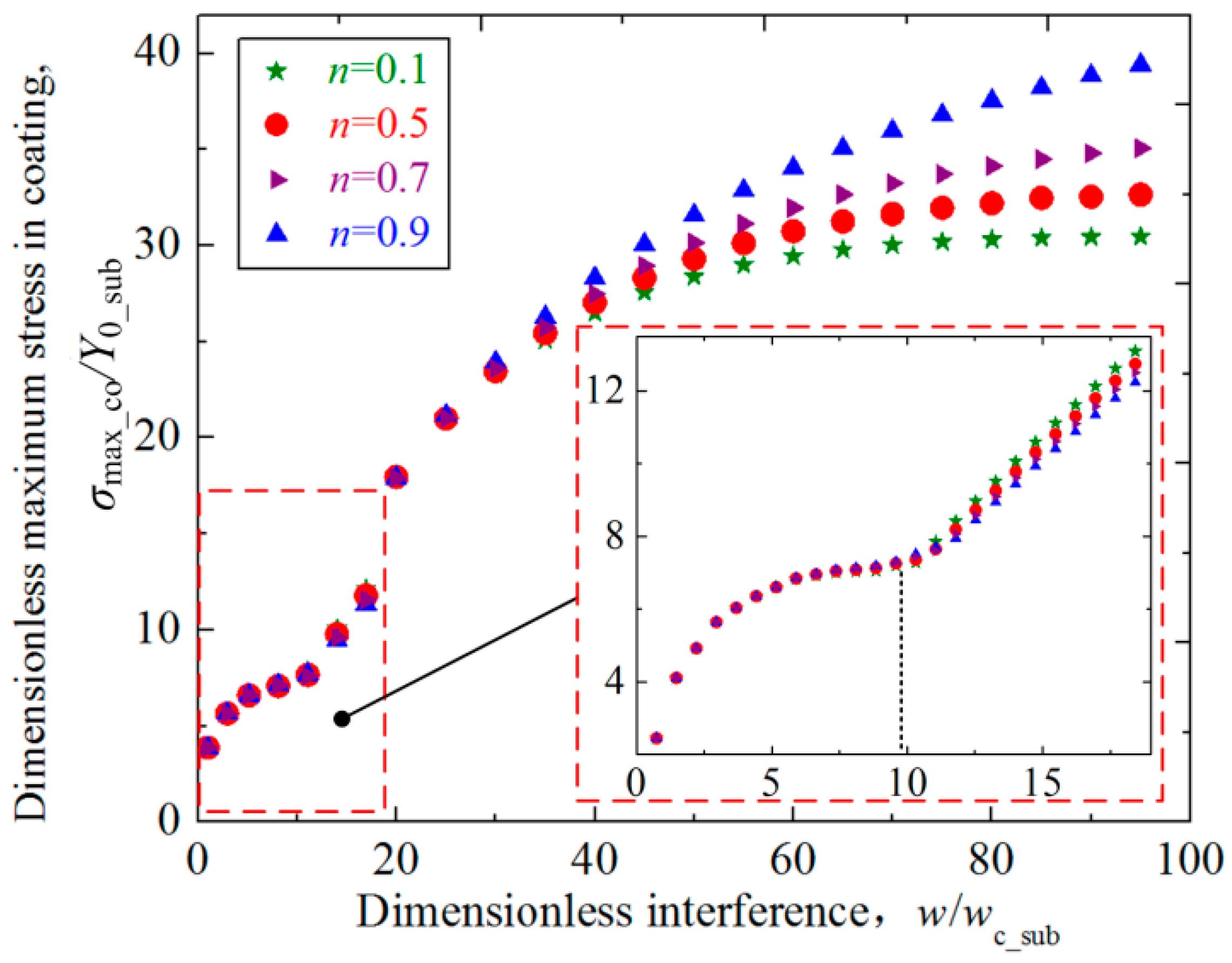
The distribution and intensity of the contact stress is closely related to the possible failure modes in the coated asperity contact, and the effect of the substrate hardening exponent on the stress should be investigated.
Figure 8 shows the relation between the dimensionless maximum von Mises stress in the coating
σmax_co/
Y0_sub and the dimensionless interference
w/
wc_sub for some selected hardening exponents of the substrate
n = 0.1, 0.5, 0.7, 0.9. The dimensionless coating thickness
t/
R = 0.01, and Young’s modulus ratios
Eco/
Esu = 4. It could be seen from
Figure 8 that the maximum stress increases as the interference
w/
wc_sub becomes larger. Under the small interference, the effect of the substrate with different
n values on the maximum stress in the coating is negligible. Then the dimensionless interference
w/
wc_sub gets larger ranging from 12 to 40, the maximum stress still shows to be slightly influenced by the
n values. While the interference
w/
wc_sub is above 40, the effect of the
n value on the maximum stress could not be omitted, and larger
n values of the substrate result in larger maximum stresses in the coating. This is expected since the larger
n values means more elastic substrate, and the same interference will lead to larger maximum stress for the asperities with these kind of substrates.
An inflection point, where the slope of the increase of maximum stresses changes, appears when the value of
w/
wc_sub approximately equals to 9 for all
n cases as revealed in
Figure 8. All curves for different
n cases consolidate to a single curve when the interferences are less than the inflection point. After the inflection point, the curves separate from each other, and the maximum stress in the coating for larger
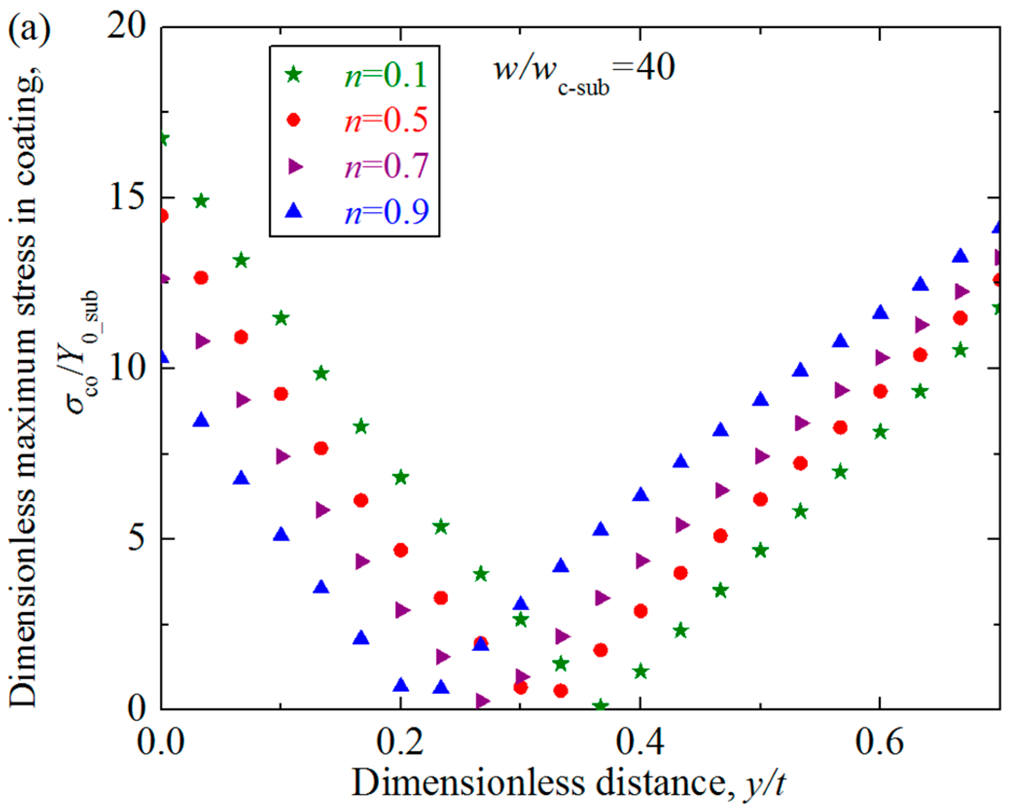
n cases increases more quickly. To study the reason of the appearance of the inflection point, the distribution of the equivalent von Mises stresses
σco/Y0_sub in the coating along the axis of symmetry (
y axis) was considered at different interferences near the inflection point in
Figure 9. It shows that the inflection point appears approximately at dimensionless interference
w/
wc_sub = 9 in
Figure 8, thus the stress distributions are studied for the cases where interferences range from
w = 6
wc_sub to
w = 25
wc_sub. The geometrical and material parameters were set as those in
Figure 8. The dimensionless vertical distance
y/
t changes from 0 to 1, meaning the position from the contact surface to the interface between the substrate and the coating. It could be seen from
Figure 9 that for the case
w/
wc_sub = 6 which is below the inflection point, the maximum stress appears approximately at the dimensionless vertical distance
y/
t = 0.28, a position close to the contact surface. For the case
w/
wc_sub = 12 and 25 which is above the inflection point, the maximum stress appears at the interface between the substrate and the coating (
y/
t = 1). While for the case
w/
wc_sub = 9 which is almost the inflection point, the maximum stress appears at two positions: one is at the position
y/
t = 0.28 close to the contact area; the other is at the interface. As revealed in Ref. [
16], the equivalent von Mises stress in the coating is influenced by two factors: One is the applied contact load and the other is mismatch of elastic modulus. At the position close to the contact surface, the factor of contact load is crucial, while at the interface between the substrate and coating, the factor of the elastic modulus mismatch is dominant. The inflection point appears at the interference where the two factors have the same contributions, leading to two equal maximum stress at different positions.
It could be seen from
Figure 9 that the distribution and maximum value of the stresses along the axis of symmetry is little affected by the hardening exponent when the interference is small, such as
w/
wc_sub less than 9. While as the dimensionless interference
w/
wc_sub increases from 12, the distribution of the stress shows to be affected by the values of the substrate hardening exponents to some extent. A notable phenomenon is that as the interference increases, the stress at the position close to the contact surface decreases to zero, which means a low stress zone appears. This phenomenon accords with the conclusion given in Ref. [
19]. To show this phenomenon more clearly,
Figure 10 presents the stress distribution along the axis of symmetry in the coating for the cases
w/
wc_sub = 40 and 70. From
Figure 9 and
Figure 10, it could also be found that as the interference increases, the low stress zone moves from the position very close to the contact surface (e.g.,
w/
wc_sub = 12) to the deeper position. Under the same interference, the low stress zone is closer to the contact surface for the larger
n cases.


