Development of a Multi-Pass Drawing Process Design System for Steel Profiles


Abstract
:1. Introduction
2. Theories for Process Design
2.1. Design of an Intermediate Die Shape
2.2. Calculation of the Profile Drawing Load
2.3. Determination of the Number of Passes
3. Process Design System
3.1. Procedure of Process Design
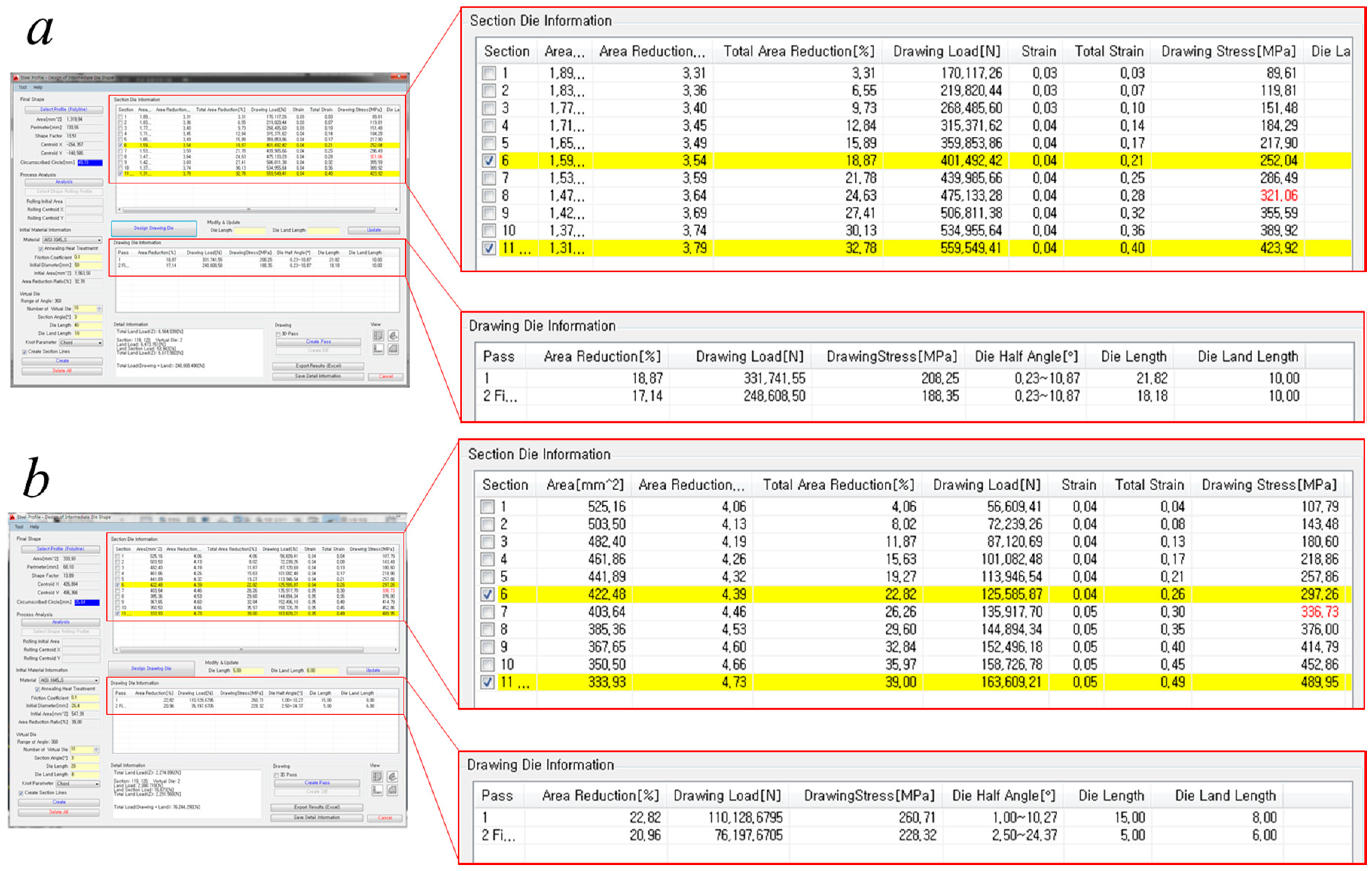
3.2. Design Assist Program
4. Application of the Process Design System
5. Numerical and Experimental Validation
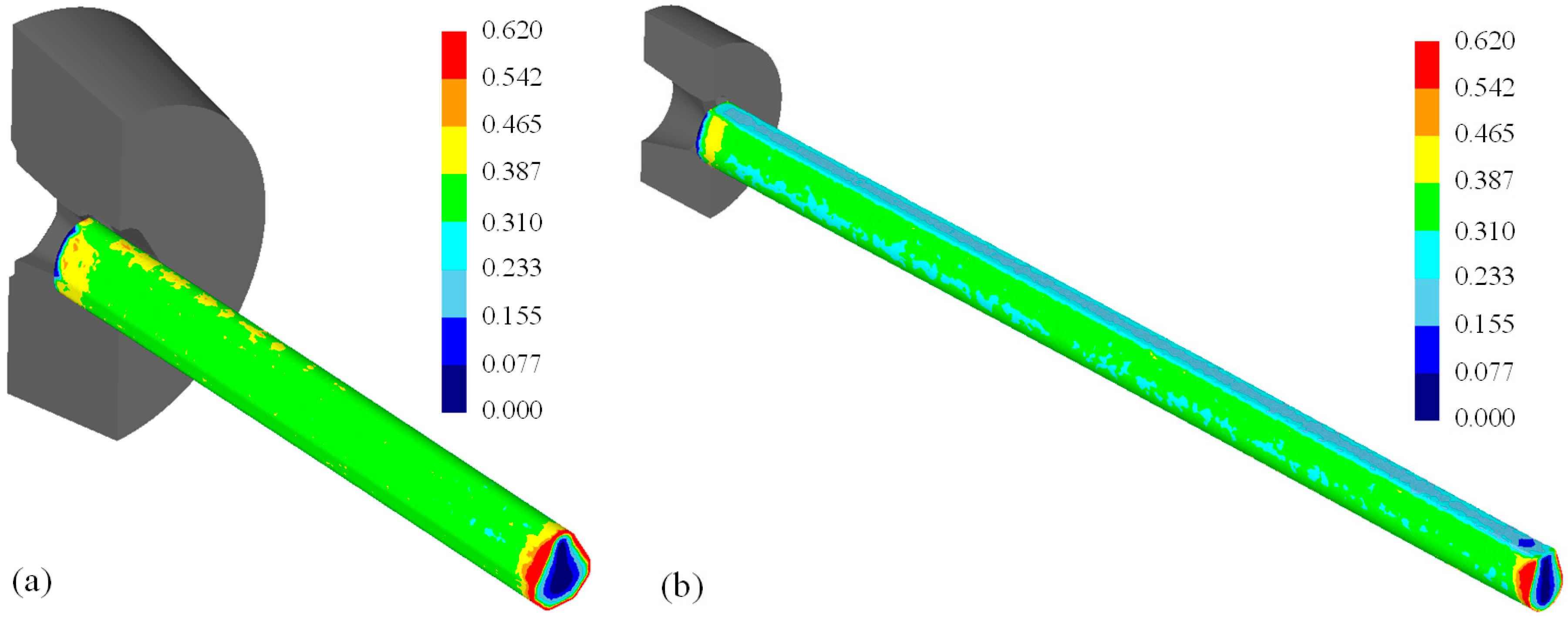
5.1. Numerical Validation of the Designed Process
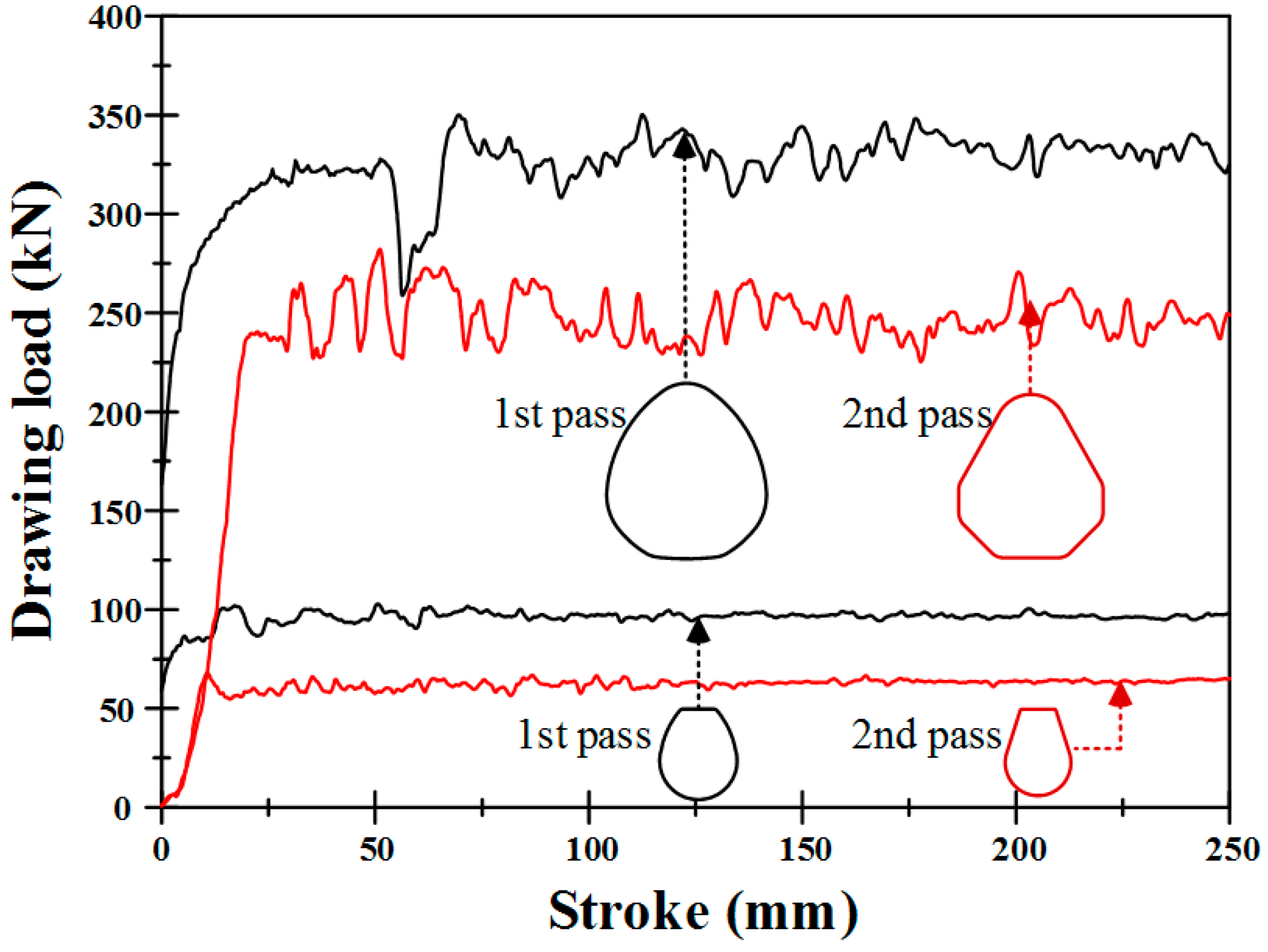
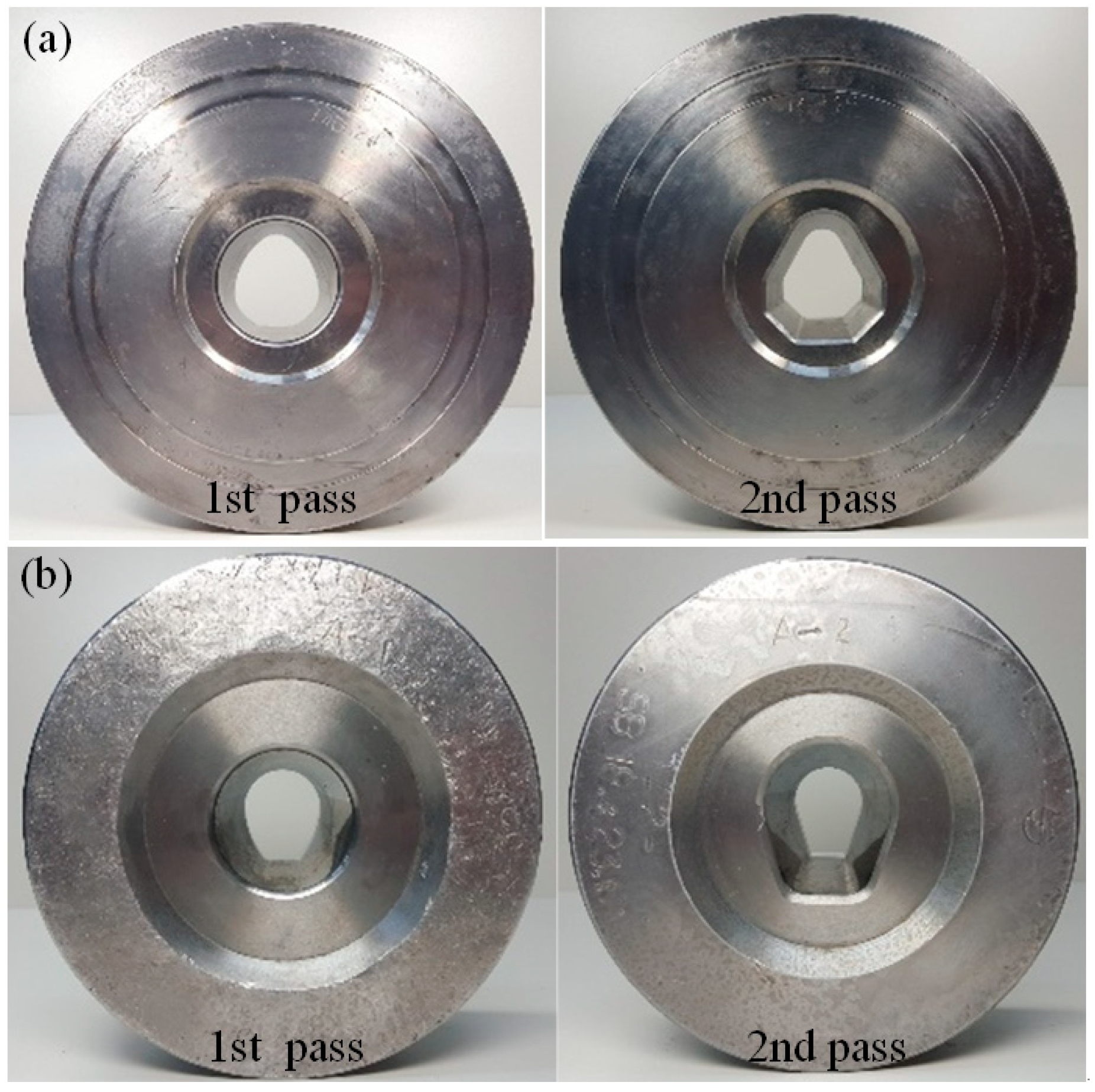
5.2. Profile Drawing Experiment
6. Conclusions
- (1)
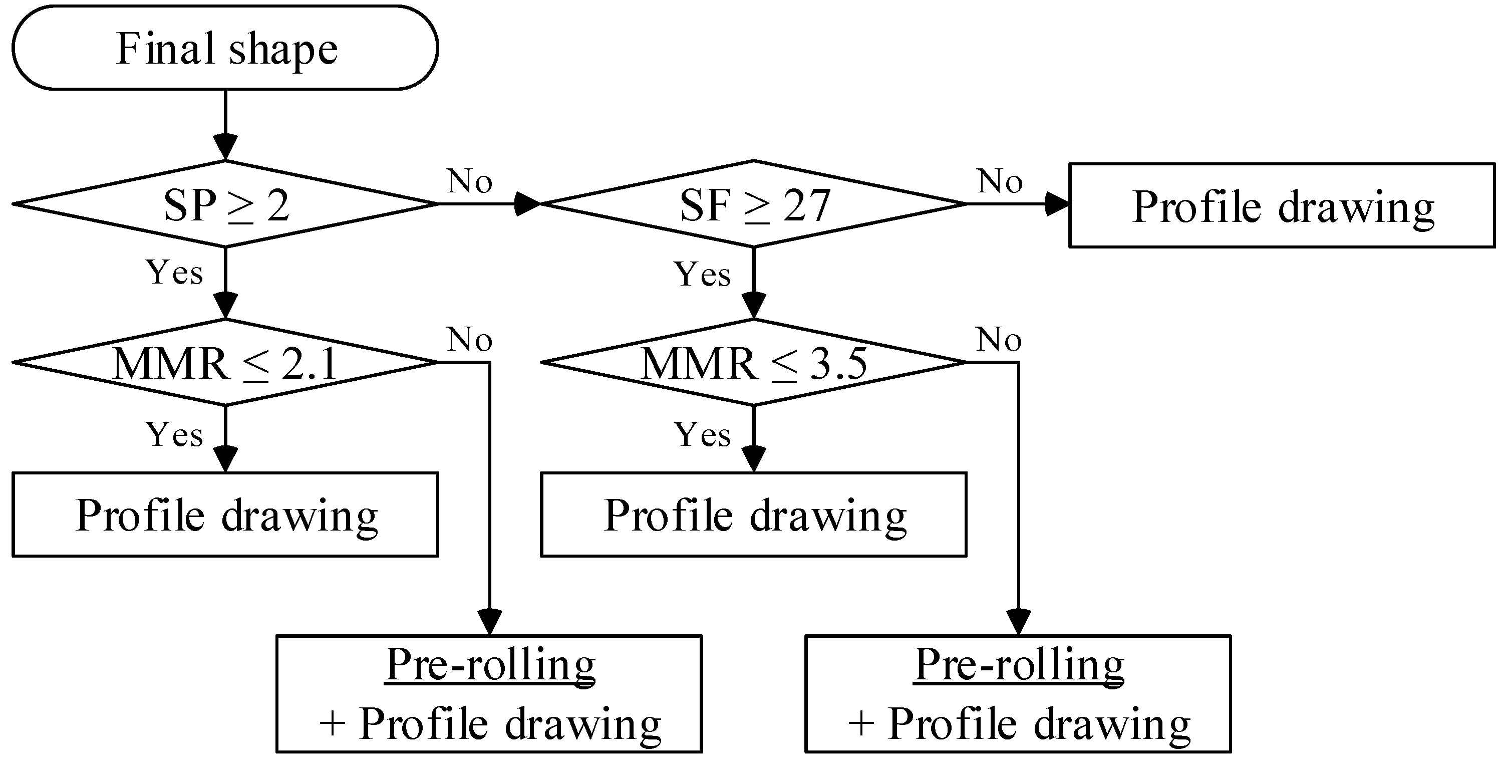
- In this study, the criteria of process classification were established. It can be determined whether the pre-rolling process is necessary or not based on the criteria.
- (2)
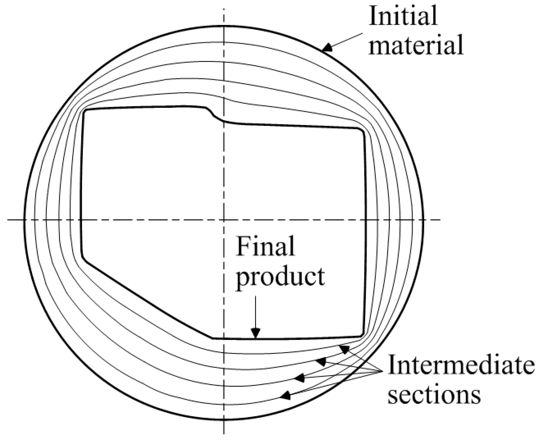
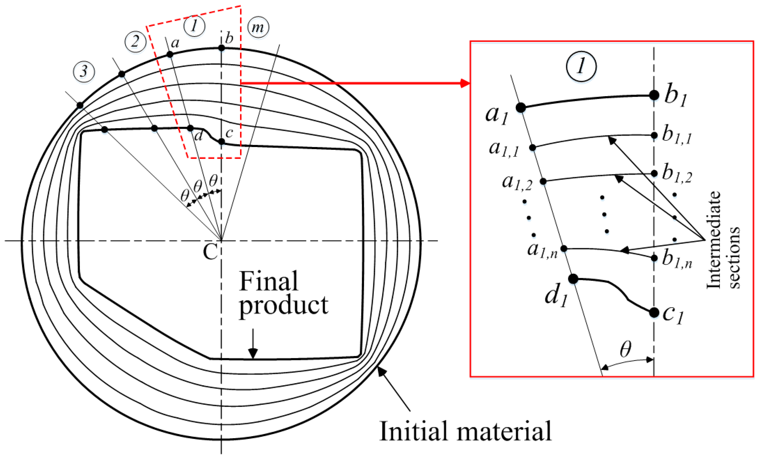
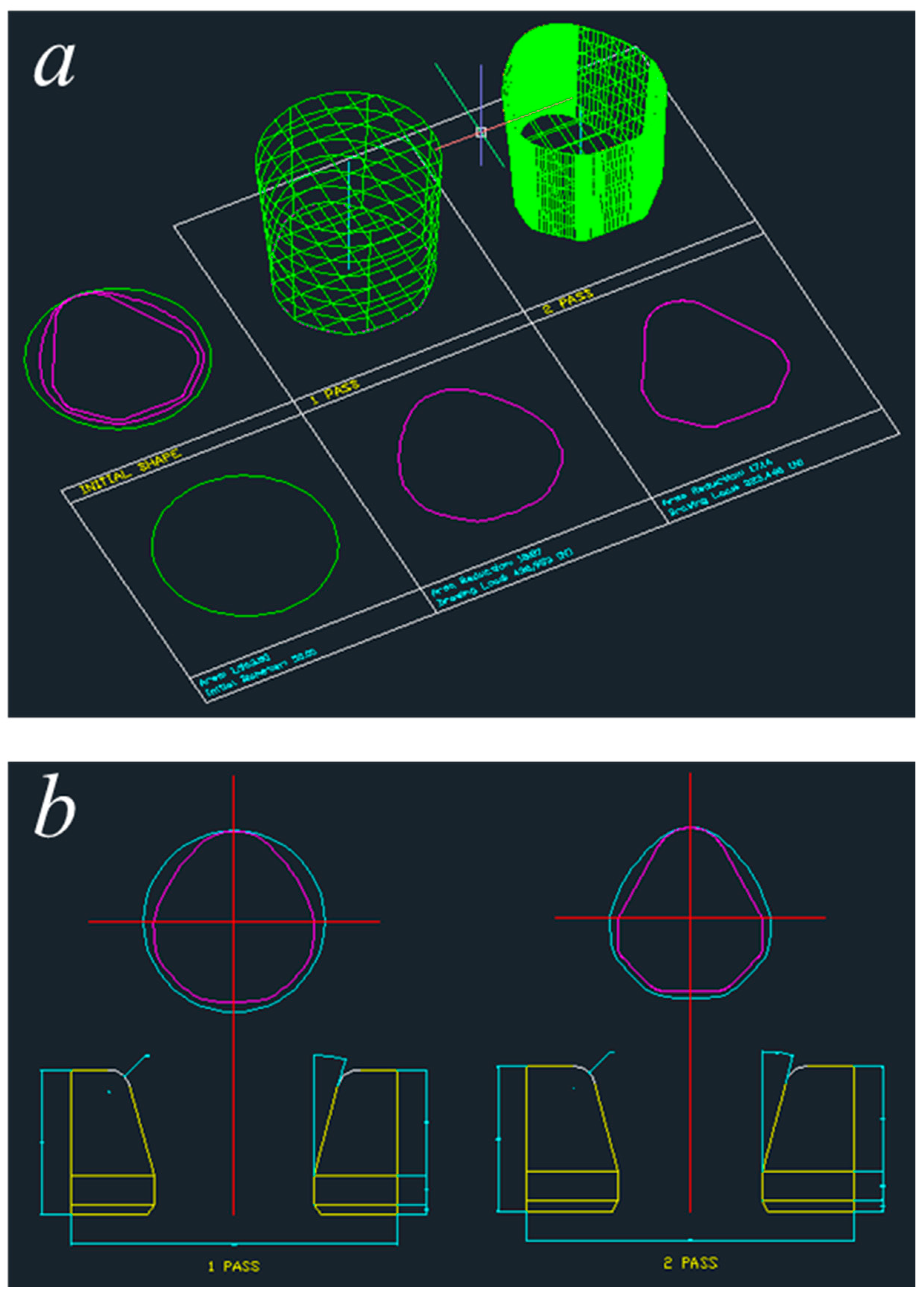
- The intermediate die shapes for multi-pass profile drawing were determined by using the intermediate sections between the initial and final cross-sectional shapes, the reduction area, the yield strength of the material, and the designer’s experience.
- (3)
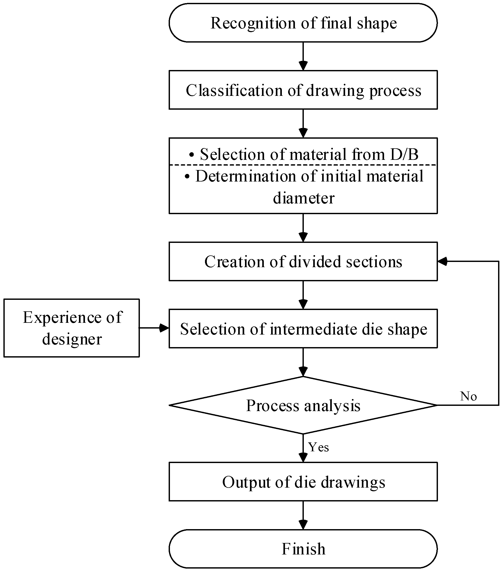
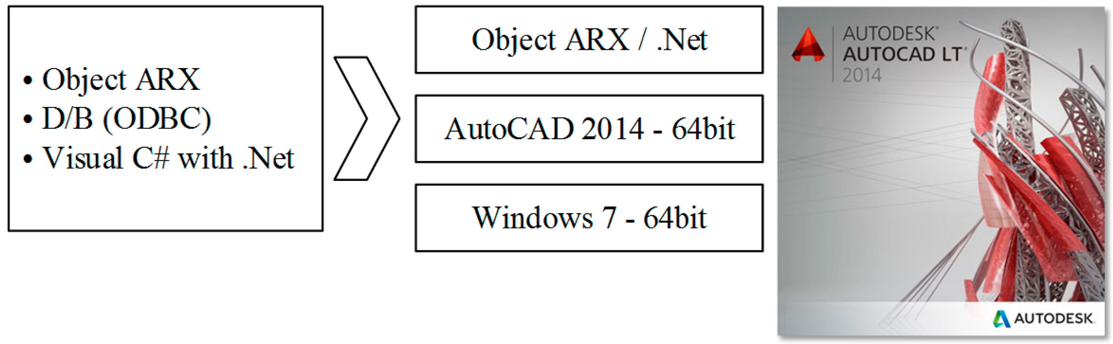
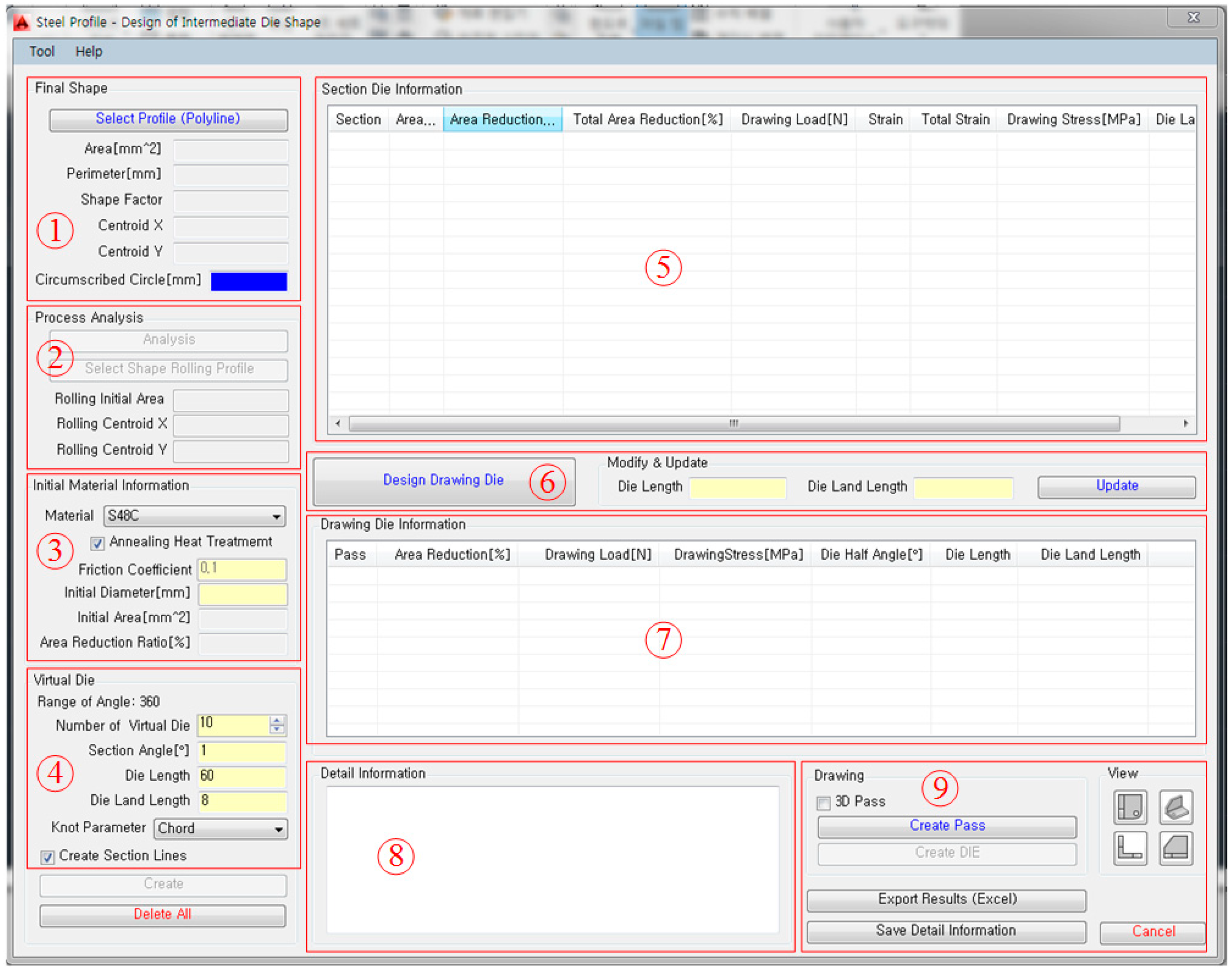
- The developed process design system is operated through a user-friendly GUI window. This window provides the user with diverse information including the final shape, the reduction area, the drawing load, the drawing stress, and the strain. Based on this information, as well as the designer’s experience, the process design can be carried out.
- (4)
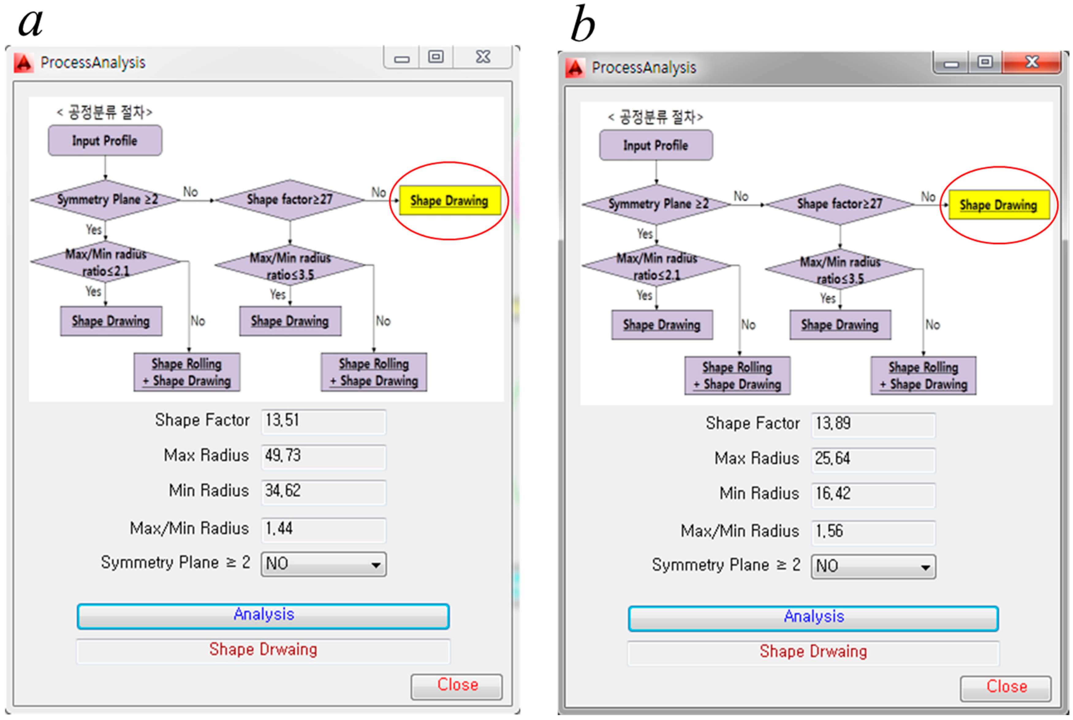
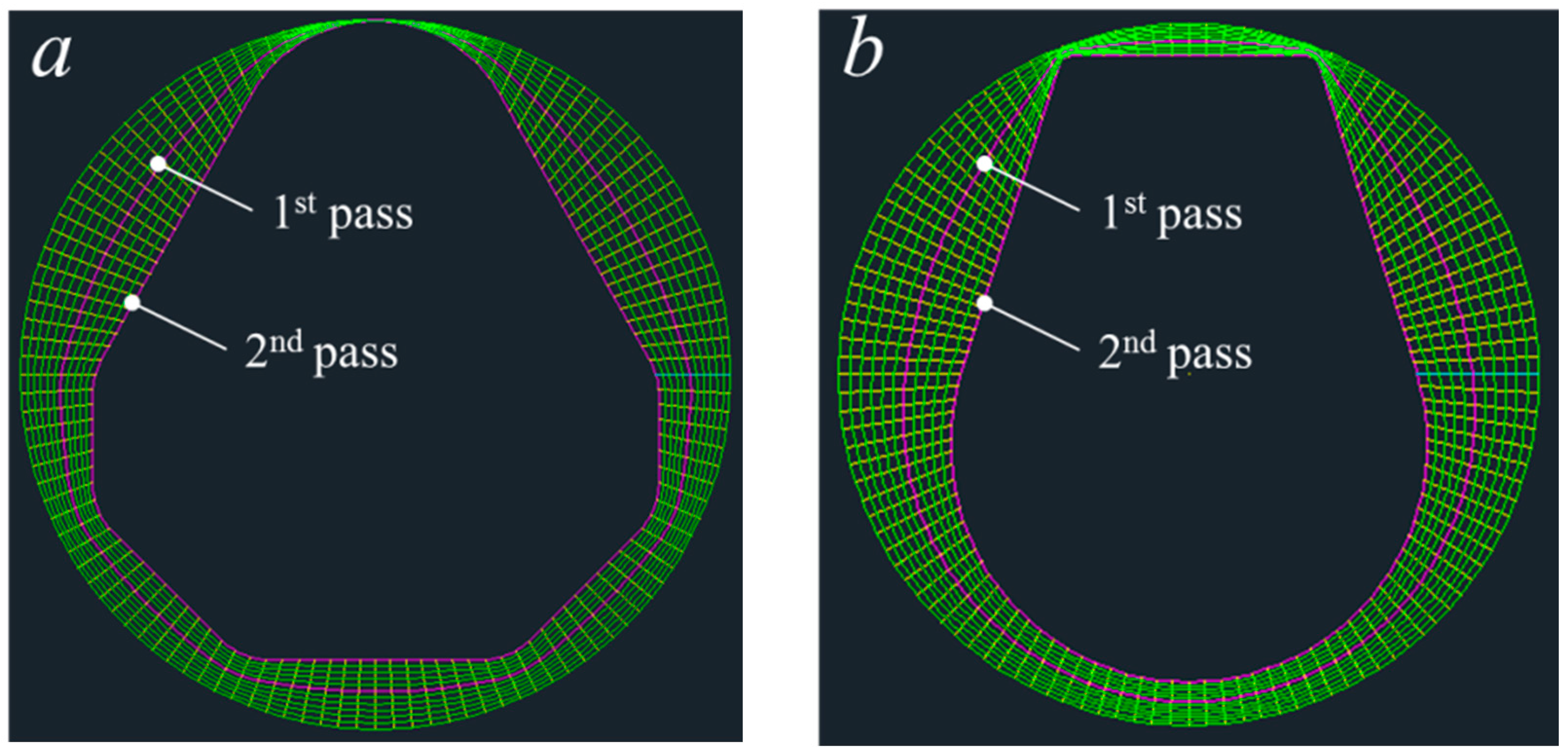
- To verify the effectiveness of the design system, multi-pass profile drawing processes for two profiles (one with a diamond cross-sectional shape the other with a teardrop cross-sectional shape) were designed. The results of the design system, FE analysis, and experiment showed that the drawing loads obtained were consistent with a maximum difference between drawing loads of approximately 11%. Moreover, the final profile obtained by experiment had a dimensional accuracy within the specified tolerance.
- (5)
- The results of this study show that the developed design system is a useful method for designing the multi-pass profile drawing process. Future studies need to build on this study by providing an additional capability of designing the pre-rolling process. This will allow the design system to be used more effectively.
Author Contributions
Funding
Conflicts of Interest
References
- Kim, Y.C.; Kim, D.J.; Kim, B.M. Intermediate die design system for the multi-stage drawing process. Trans. NAMRI/SME 2000, 28, 69–74. [Google Scholar]
- Yoshida, K.; Tuihiji, S. Multiple drawing of rails for linear motion guide. In Proceedings of the 7th ICTP, Yokohama, Japan, 27 October–1 November 2002; pp. 367–372. [Google Scholar]
- Brücker, M.; Keller, D.; Reissner, J. Computer-aided drawing of profile from round and square bar. CIRP Ann. 1998, 37, 247–250. [Google Scholar] [CrossRef]
- Steff, W.; Kopp, R. Estimation of designing methods for the drawing of section rods and wire. Wire J. Int. 1995, 28, 104–109. [Google Scholar]
- Sawamiphakdi, K.; Lahoti, G.D.; Gunasekera, J.S.; Kartik, R. Development of utility programs for a cold drawing process. J. Mater. Process. Technol. 1998, 80–81, 392–397. [Google Scholar] [CrossRef]
- Kampuš, Z. Analysis of factors influencing accuracy in the drawing of round rods. J. Mater. Process. Technol. 1999, 87, 90–96. [Google Scholar] [CrossRef]
- Renz, J.R.; Kopp, R. A new calibration method for complex shape sections with reflex angles. Wire J. Int. 1998, 31, 104–109. [Google Scholar]
- Norasethasopon, S.; Yoshida, K. Influences of inclusion shape and size in drawing of copper shaped-wire. J. Mater. Process. Technol. 2006, 172, 400–406. [Google Scholar] [CrossRef]
- Lee, S.K.; Lee, J.E.; Kim, S.M.; Kim, B.M. Design of intermediate die shape of multistage profile drawing for linear motion guide. J. Mech. Sci. Technol. 2010, 24, 2539–2544. [Google Scholar] [CrossRef]
- Lee, S.H.; Lee, S.K.; Kim, B.M. Study on the manufacturing process of precision linear guide rail through shape rolling and profile drawing. J. Mech. Sci. Technol. 2010, 24, 1647–1653. [Google Scholar] [CrossRef]
- Lin, Z.; She, B.; Sun, F.; Zhang, Z. Numerical and experimental investigation of trapezoidal wire cold drawing through a series of shaped dies. Int. J. Adv. Manuf. Technol. 2015, 76, 1383–1391. [Google Scholar] [CrossRef]
- Fiorentino, A.; Feriti, G.C.; Giardini, C.; Ceretti, E. Part precision improvement in increamental sheet forming of not axisymmetric parts using an artificial cognitive system. J. Manuf. Syst. 2015, 35, 215–222. [Google Scholar] [CrossRef]
- Gupta, S.K.; Rajagopal, D. Sheet metal bending: Forming part families for generation sheet shared press-brake setups. J. Manuf. Syst. 2002, 21, 329–349. [Google Scholar] [CrossRef]
- Basily, B.B.; Sansome, D.H. Some theoretical considerations for the direct drawing of section rod from round bar. Int. J. Mech. Sci. 1976, 18, 201–208. [Google Scholar] [CrossRef]
- Kim, S.M.; Lee, S.K.; Lee, C.J.; Kim, B.M.; Lee, S.B.; Jeong, M.S. Innovative process design of multistage profile drawing for precision guide rail. Steel Res. Int. Spec. Ed. Met. Form. 2012, 2012, 483–486. [Google Scholar]
- Lee, I.K.; Lee, S.K.; Lee, C.J.; Jeong, M.S.; Lee, J.W. A new method for predicting drawing load of shape drawing process. Int. J. Adv. Manuf. Technol. 2016, 84, 1747–1755. [Google Scholar] [CrossRef]
- Trofimov, V.N.; Kuznetsova, T.V. Stress of drawing solid rectangular profiles. Russ. J. Nonferr. Met. 2013, 54, 21–25. [Google Scholar] [CrossRef]
- Geleji, A. A Bildsame Forming der Metalle in Rechnung und Versuch; AKADEMIE-VERLAG GmbH: Berlin, Germany, 1960; pp. 4–21. (In German) [Google Scholar]
- JSTP. Wire Drawing; KORONA: Tokyo, Japan, 1990; p. 44. (In Japanese) [Google Scholar]


| Conditions | Diamond Cross Section | Teardrop Cross Section |
|---|---|---|
| Area of the profile (mm2) | 1319.94 | 333.93 |
| Perimeter of the profile (mm) | 133.55 | 68.10 |
| Shape factor | 13.51 | 13.89 |
| Diameter of the minimum circumscribed circle (mm) | 49.73 | 25.64 |
| Material | AISI 1045 | AISI 1045 |
| Annealing heat treatment between passes | apply | apply |
| Friction coefficient () | 0.05 | 0.05 |
| No. of intermediate sections | 10 | 10 |
| Die length between inlet and exit of die (mm) | 40.0 | 20.0 |
| Die land length (mm) | 10 | 8 |
| Profile | First Pass | Second Pass |
|---|---|---|
| Diamond cross section | 18.8% | 17.1% |
| Teardrop cross section | 22.8% | 20.9% |
| Conditions | Diamond Cross-Section | Teardrop Cross-Section |
|---|---|---|
| Drawing velocity (mm/s) | 100.0 | 100.0 |
| No. of elements | 137,825 | 196,177 |
| No. of nodes | 29,911 | 41,803 |
| Friction coefficient (μ) | 0.05 | 0.05 |
| Method | Pass | Diamond Cross-Section | Teardrop Cross-Section |
|---|---|---|---|
| FE analysis | 1 | 318.8 | 101.0 |
| 2 | 237.4 | 65.7 | |
| Design program | 1 | 331.6 | 109.9 |
| 2 | 248.2 | 73.6 | |
| Experiment | 1 | 316.9 | 103.0 |
| 2 | 240.3 | 69.7 |
© 2018 by the authors. Licensee MDPI, Basel, Switzerland. This article is an open access article distributed under the terms and conditions of the Creative Commons Attribution (CC BY) license (http://creativecommons.org/licenses/by/4.0/).
Share and Cite
Lee, S.-K.; Lee, I.-K.; Lee, S.-Y. Development of a Multi-Pass Drawing Process Design System for Steel Profiles. Materials 2018, 11, 2446. https://doi.org/10.3390/ma11122446
Lee S-K, Lee I-K, Lee S-Y. Development of a Multi-Pass Drawing Process Design System for Steel Profiles. Materials. 2018; 11(12):2446. https://doi.org/10.3390/ma11122446
Chicago/Turabian StyleLee, Sang-Kon, In-Kyu Lee, and Sung-Yun Lee. 2018. "Development of a Multi-Pass Drawing Process Design System for Steel Profiles" Materials 11, no. 12: 2446. https://doi.org/10.3390/ma11122446