Article

Semiconductor-Ionic Nanocomposite La0.1Sr0.9MnO3−δ-Ce0.8Sm0.2O2−δ Functional Layer for High Performance Low Temperature SOFC

Hubei Collaborative Innovation Center for Advanced Organic Chemical Materials, Hubei Key Laboratory of Ferro & Piezoelectric Materials and Devices, Faculty of Physics and Electronic Science, Hubei University; Wuhan 430062, Hubei, China
*
Authors to whom correspondence should be addressed.
Materials 2018, 11(9), 1549; https://doi.org/10.3390/ma11091549
Submission received: 27 July 2018 / Revised: 24 August 2018 / Accepted: 24 August 2018 / Published: 28 August 2018
(This article belongs to the Section Energy Materials)

Abstract

:
A novel composite was synthesized by mixing La0.1Sr0.9MnO3−δ (LSM) with Ce0.8Sm0.2O2−δ (SDC) for the functional layer of low temperature solid oxide fuel cell (LT-SOFC). Though LSM, a highly electronic conducting semiconductor, was used in the functional layer, the fuel cell device could reach OCVs higher than 1.0 V without short-circuit problem. A typical diode or rectification effect was observed when an external electric force was supplied on the device under fuel cell atmosphere, which indicated the existence of a junction that prevented the device from short-circuit problem. The optimum ratio of LSM:SDC = 1:2 was found for the LT-SOFC to reach the highest power density of 742 mW·cm−2 under 550 °C The electrochemical impedance spectroscopy data highlighted that introducing LSM into SDC electrolyte layer not only decreased charge-transfer resistances from 0.66 Ω·cm2 for SDC to 0.47–0.49 Ω·cm2 for LSM-SDC composite, but also decreased the activation energy of ionic conduction from 0.55 to 0.20 eV.

Graphical Abstract

1. Introduction

Solid oxide fuel cells (SOFCs) research and development have been strongly driven towards low temperature (LT), <600 °C, operations. Thereby, the materials and technology associated with LT demand extensive research efforts. Among the three basic components of SOFC, the electrolyte is the core. Yttria-stabilized zirconia (YSZ) has dominated the SOFC R&D over many decades since it was first discovered by Nernst [1] in 1899. However, its sufficient O2− conductivity, ~0.1 S cm−1, only takes place under high temperature (~1000 °C) [2,3], leading to high system costs and complexity, severe drawback on material durability, slow start-up rate, thus impeding the SOFCs commercial process. Therefore, the LTSOFC research and development have become worldwide, but to maintain the high efficiency and to design high ionic conductive electrolyte materials functioned at low temperatures, have been a critical challenge [4,5,6,7,8].
For developing new oxide-ion conducting materials aiming to replace YSZ as the electrolyte for LTSOFCs, the most common way is the structural design by doping to create structural defects, thus increasing ionic conductivity. Goodenough [9] proposed that the conductivity of oxide-ion conductors could be effectively enhanced by designing materials structure. For example, doping low valent cations can enhance the ionic conductivity by introducing oxygen vacancies. Although various electrolyte materials have been discovered following this line, there have been no alternative materials so far. Doped ceria possesses excellent O2− conductivity (0.1 S cm−1) under 800 °C, 200 °C below than that of the YSZ [10,11,12]. However, the electronic conduction characteristic, owing to the Ce4+ to Ce3+ reduction in fuel cell operation, leading to losses for open circuit voltage (OCV) of the SOFC with doped ceria electrolytes [13].
Based on the previous studies, a novel way to develop effectively ionic conducting electrolytes by constructing more interfaces between the two-phase composite materials has been developed. At the hetero-interfacial region, highly disordered microstructure provides a large number of structural defects which can provide fast conducting pathways [2,14,15,16,17,18].
Zhu et al. [19,20,21,22,23,24,25,26,27] designed nano-composite two-phase materials with super ionic conduction by constructing hetero-interface with super ionic conduction, honored as ‘ion highway’ [28]. They significantly enhanced the material conductivity under lower temperature. Barriocanal et al. [2] fabricated hetero-structures by sandwiching YSZ electrolyte layers with different thicknesses between two layers of semiconducting SrTiO3 (STO). They found that the interface between hetero-structures (e.g., YSZ/STO) supplied both higher carrier concentration and lower activation energy of ionic conduction, thus yielding many orders to increase their ionic conductivity. Yao et al. [14] enhanced the ionic conductivity of single-layered SDC film about 5 times by constructing Ce0.8Sm0.2O2−δ/Al2O3 multilayer structure, demonstrating that increasing hetero-interface is beneficial to enhance ionic interfacial conductivity. According to their study results, the higher interfacial conductivity of Ce0.8Sm0.2O2−δ/Al2O3 multilayer structure is due to more structural defects at interfacial regions with highly-disordered microstructures. However, an important materials nature is missed. All of these heterostructures are constructed between the ionic conductor and the semiconductor, so it is more appropriate to name it as the semiconductor-ionic heterostructure. Based on this line, we can explore many new opportunities. Some of them have been reported [29,30,31], but there is a great potential for more research avenues to be explored.
Considering the high O2− conductivity of SDC between 500 and 1000 °C and its good compatibility with Lanthanum strontium manganite perovskites, we mixed the lanthanum strontium manganite perovskites with SDC to develop a semiconductor-ionic nanocomposite functional layer for SOFC. Study results revealed that the composite possessed better conductivity and electrochemical performance than the conventional pure SDC electrolyte.

2. Experimental

2.1. Materials Synthesis and Physical Characterizations

Both La0.1Sr0.9MnO3−δ (LSM) with Ce0.8Sm0.2O2−δ (SDC) materials were synthesized by co-precipitation method. For LSM synthesis, 0.0025 mol La(NO3)3·6H2O (Aladdin Industrial Corporation, Shanghai, China), 0.0225 mol Sr(NO3)2 (Sinopharm Chemical Reagent Co., Ltd., Shanghai, China), and 0.025 mol Mn(NO3)2 (Sinopharm Chemical Reagent Co., Ltd., Shanghai, China) were dissolved in 100 mL deionized water. Na2CO3 (Sinopharm Chemical Reagent Co., Ltd., Shanghai, China) solution (0.5 mol L−1, 154 mL) was added to the above solution dropwise. After 2 h stirring, it was left to be aged for 12 h. The precipitation was filtrated by Buchner funnel (Jiangsu Sanaisi Scientific Instrument Corporation, Jiangsu, China), followed by washing with de-ionic water, drying at 120 °C for 2 h, and then calcinated at 1000 °C for 6 h to get the LSM sample. The SDC was synthesized with the similar steps, except for the calcinations condition (800 °C for 4 h).
The LSM-SDC composites were fabricated by grinding the mixture of LSM and SDC powders manually with the agate mortar.

2.2. Material Characterizations

X-ray diffraction (XRD) measurement was conducted on Bruker D8 (Cu Kα radiation, λ = 0.154 nm, Bruker Corporation, Karlsruhe, Germany). The sample morphologies and chemical compositions were examined by scanning electron microscope (FE-SEM, JSM7100F, Japan Electron Optics Laboratory Co., Ltd., Tokyo, Japan) equipped with energy-dispersive X-ray (EDX, Japan Electron Optics Laboratory Co., Ltd., Tokyo, Japan) spectrometer.

2.3. Electrochemical Measurement

The nickel foam-NCAL (Ni0.8Co0.15Al0.05LiO2−δ, Tianjin B&M Science and Technology Joint-Stock Co., Ltd., Tianjin, China) electrodes were prepared by the brush coating-method [32,33]. After being pressed, the thickness of the Ni-NCAL electrode was about 0.4 mm. The Ni-NCAL (anode and cathode) and LSM-SDC (electrolyte layer) were dry-pressed (200–300 MPa pressure) together to obtain the SOFC device. There was no further firing procedures before testing the device to protect the hetero-interfaces between LSM and SDC [19,20]. Fuel cell thickness and effective areas were 0.7 mm and 0.64 cm2, respectively.
The electronic load (type IT8512C+, ITECH Electronic Co., Ltd., Nanjing, China) was used to evaluate the fuel cell performance (with air and H2 as oxidant and fuel, respectively). Electrochemical impedance spectroscopy (EIS) measurement was conducted by Gamry Ref 3000 (Gamry Instruments, Philadelphia, PA, USA) under OCV (amplitude: 10 mV, frequency range: 1 MHz–0.1 Hz). An equivalent circuit mode LRΩ(RaZa)((RbZb)(RcZc) was used to fit the original EIS data by ZView (Copyright 1990–2007 Scribner Associates, Inc., Southern Pines, NC, USA, written by Derek Johson). The electronic conductivities of LSM-SDC composites were measured by Keithley 2400 SourceMeter (Tektronix Corporation, Beaverton, WA, USA).

3. Results and Discussion

As shown in Figure 1, the characteristic peaks of LSM corresponded to a perovskite SrMnO3 structure. The diffraction peaks of prepared SDC material were indexed to standard diffraction pattern for fluorite CeO2 structure, indicating that Sm was doped into the crystal lattice of ceria. The major diffraction peaks of the original 1LSM-2SDC composite belonged to SDC. The characteristic peaks of LSM in the pattern of the original 1LSM-2SDC composite were not obvious due to the smaller amount of LSM in the composite. Compared with the 1LSM-2SDC composite material, there was no new phase in the XRD pattern of 1LSM-2SDC, which was heat-treated at 550 °C for 2 h under the air atmosphere, indicating that the composite is thermal stable under 550 °C. The average crystal sizes of SDC and LSM were estimated according to the Debye-Scherrer equation from the peaks at 28.3° and 35.2°, respectively. Both of them were nanoscale, 46 nm for SDC and 37 nm for LSM. The small radius of the materials was beneficial to increase the hetero-interfaces between LSM and SDC. After being heat-treated at 550 °C for 2 h, the average crystal size of SDC increased to about 48 nm, indicating that the SDC is stable under the fuel cell working temperature.
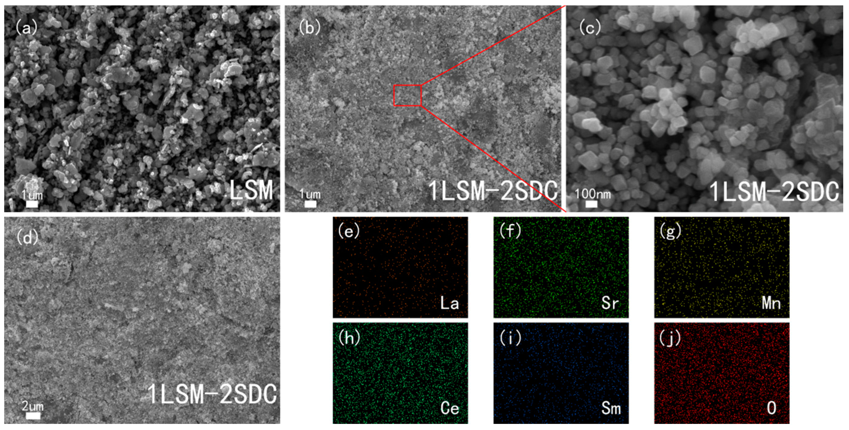
Figure 2a–d showed that the LSM particle is larger than its crystal size obtained from the XRD pattern due to the high calcinating temperature. According to Figure 2b,c the distribution of LSM and SDC in the LSM-SDC composite materials is uniform. It can be further certified by the EDS analysis (Figure 2e–j) of LSM-SDC composite materials (Figure 2d). The uniform distribution of LSM and SDC is beneficial to build continuous networks for ionic conduction.
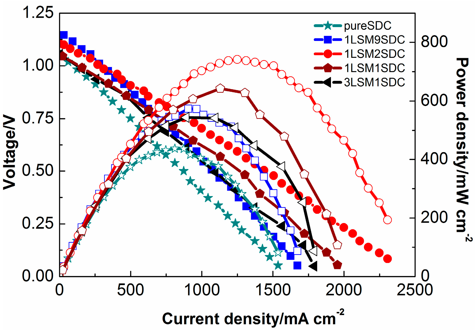
Figure 3 revealed that the SOFC performances increased with LSM contents until the weight ratio of LSM to SDC was 1:2. At this weight ratio of 1:2, the Pmax (maximum power density) 742 mW cm−2 has been achieved at 550 °C. Further increasing the content of the LSM caused a decrease in the fuel cell performance. Compared with the pure SDC, the LSM-SDC composite possessed a larger amount of hetero-interfacial region/interface, which could provide fast pathways for ionic conducting [2,14,15,16,17,18]. At the above optimum weight ratio, the ionic grain boundary conductivity was the best due to the highest hetero-interfacial area. The following characterizations will give further confirmation.
LSM is a common SOFC cathode material with excellent electronic conductivity. It is interesting that no short circuit phenomenon occurred for the SOFC using the LSM-SDC composite layer to replace the conventional electrolyte layer with the pure ionic conductor. All of the OCVs were over than 1.0 V. It may be noticed that even in the case with pure doped ceria as the electrolyte for SOFCs, short circuiting problem with low OCVs (below 1.0 V, more often 0.9 V) has been commonly observed [11,34]. Therefore, both electronic and ionic conductivities were investigated for the LSM-SDC composite samples with various weight ratios. Ag paste was brushed onto both sides of the LSM-SDC functional layer in a configuration of Ag/LSM-SDC/Ag for electrical property measurements. The electronic conductivities of LSM-SDC composites were determined by potentiostatic polarization method with the constant voltage of 0.5 V. The test temperature and atmosphere were 550 °C and N2, respectively. In the beginning, both electrons and O2− can make contributions to the current. But O2− would be exhausted with time due to no ionic resource from the N2 atmosphere, and electrons are then the only charge carriers in LSM-SDC composites when the current reach a steady state (Is) and we can get the electronic resistance Re = 0.5/Is [35]. The total resistance of the LSM-SDC composites was measured by EIS under H2/air atmosphere. The EIS results were fitted through the equivalent circuit of LRΩ(RaZa)((RbZb)(RcZc), where L-inductance, RΩ-ohmic resistance, Ra-ionic grain boundary transportation resistance, Rb(Rc)-charge-transfer resistance and Z-constant phase element. The total resistances were given by the following equation.
Rt = RΩ + Ra
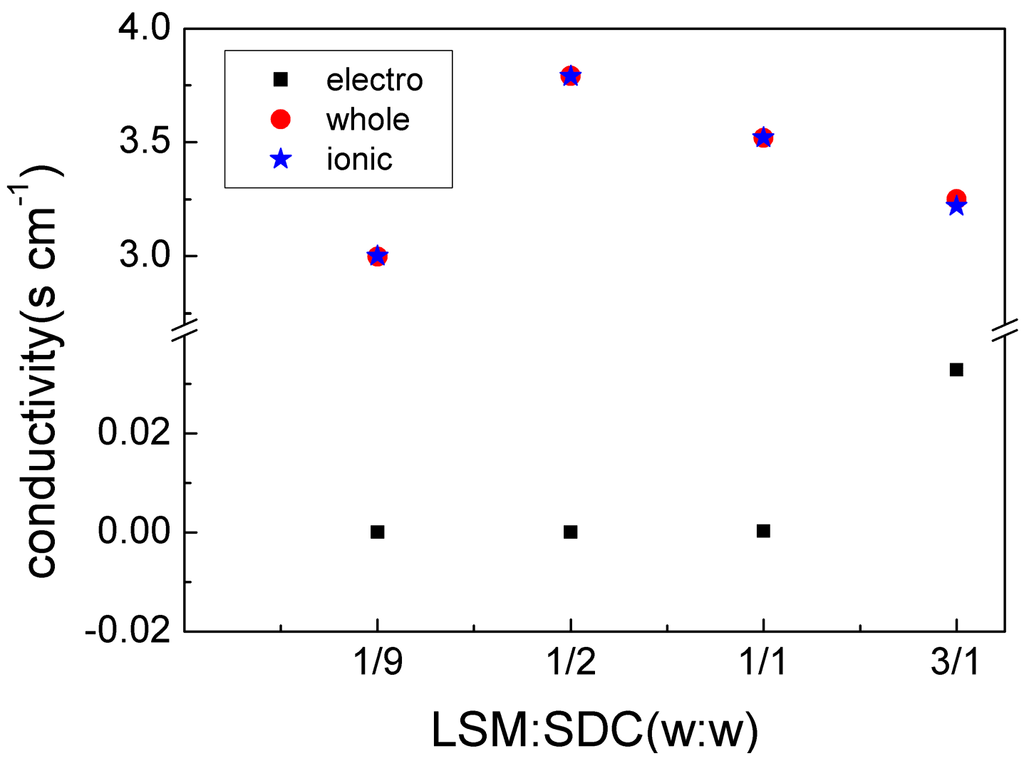
The ionic conductivity was calculated by subtracted electronic conductivity from total conductivity. The calculated data are listed in Figure 4, which revealed that the composite electronic conductivity increased with LSM content but still extremely small, indicating a low electronic conductivity owing to the discontinuity of the electronic pathway in the device.
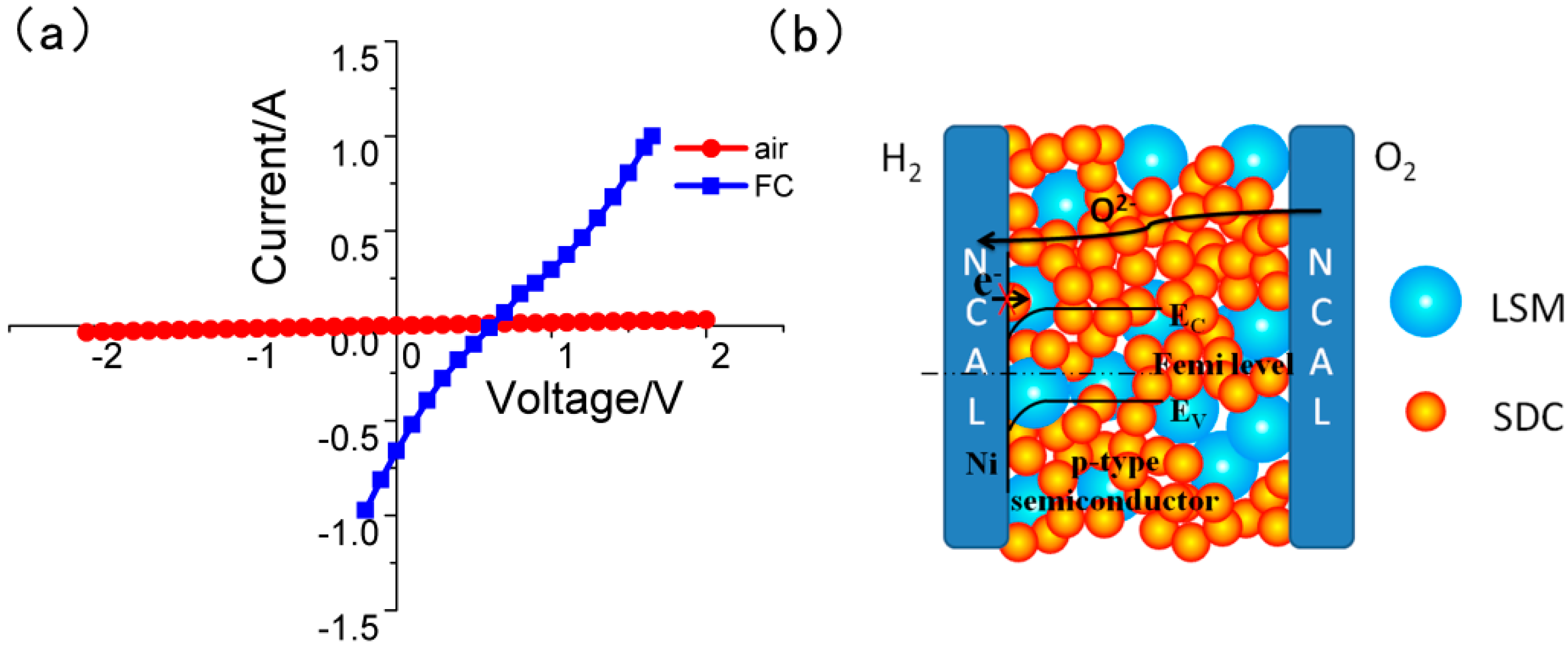
Linear scan voltage was supplied on the SOFC device with LSM-SDC (1:2, weight ratio) as the functional layer (Figure 5a). When the anode and cathode of the SOFC were both supplied with air, the I-V curve is linear, indicating that the fuel cell corresponds to a linear resistor under the air atmosphere; when the anode gas was changed into H2, the I-V curve becomes non-linear, indicating that there is a diode or rectification effect in the fuel cell device. As a kind of p-type semi-conductor, LSM, close to the anode side, can form a Schottky junction with metal Ni, production of NCAL reduction reaction [36,37]. The built-in electric field, generated by Schottky junction, not only drives the ionic transportation, but also prevents electrons transporting from the anode to cathode (Figure 5b). Therefore, even though there is some electronic conduction in the LSM-SDC composite, it can be prevented by the electronic blocking layer in the device.
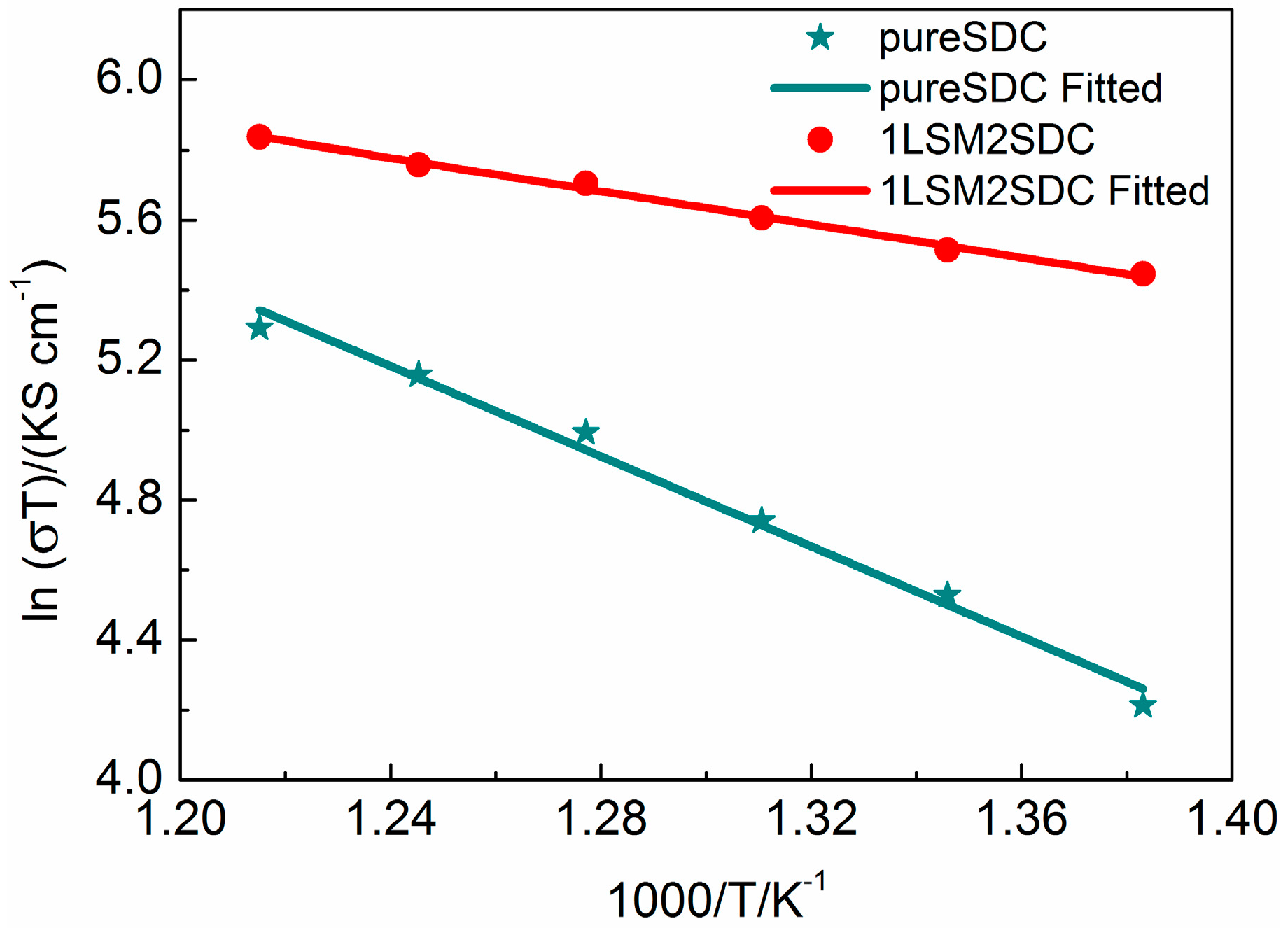
Figure 6 shows Arrhenius plots of pure SDC and LSM-SDC (1:2, weight ratio) composite at the temperature from 450 °C to 550 °C. Conductivities were measured by the EIS method in the fuel cell atmosphere. The measured EIS at different temperatures were also fitted with the equivalent circuit of LRΩ(RaZa)((RbZb)(RcZc). The conductivity σ can be obtained by
σ = δ/(A(RΩ + Ra))
where δ-pallet thickness (0.7 mm), A-pallet surface area (0.64 cm2). It is noted that two samples exhibited a linear dependence between 550 and 450 °C. The activation energy can be calculated by the slope of the linear line, which is 0.20 eV for the LSM-SDC composite (1:2, weight ratio) and 0.55 eV for SDC, respectively. This indicates that the LSM-SDC composite possesses possible interfacial conduction with lower activation energy than that of the SDC via bulk conduction of pure SDC [32]. It is consistent with the fuel cell performance in Figure 3.
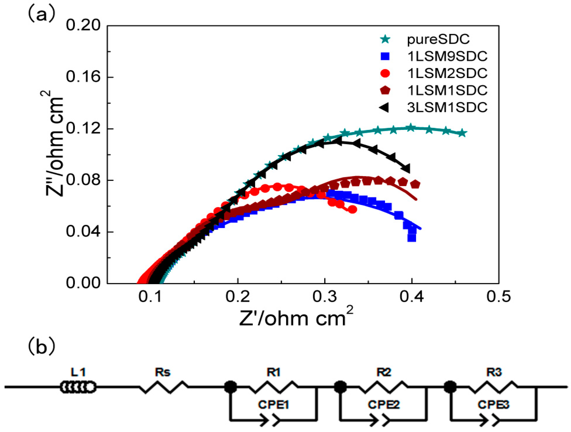
To further investigate the ionic grain boundary transportation resistance of LSM-SDC composites, the EIS measurement was conducted, and the results were revealed in Figure 7a. The intercept at high frequency reflects ohmic resistance, whereas the diameters of the semicircles at medium and low frequency reflect the ionic grain boundary transportation resistance and charge-transfer resistance, respectively [37,38]. An equivalent circuit mode LRΩ(RaZa)((RbZb)(RcZc) (Figure 7b) is still employed to fit the EIS data. The fitting results (Table 1) showed that, compared with SDC (Ra = 0.084 Ω·cm2), LSM-SDC composites possessed lower ionic grain boundary transportation resistances (Ra, 0.023–0.060 Ω·cm2). At the hetero-interface, such as between perovskite LSM material and fluorite SDC material, atomic reconstruction generates high-mobility plane with a large amount of oxygen vacancies, yielding colossal values of the ionic conductivity [2]. At the weight ratio of 1:2 (LSM:SDC), the Ra of LSM-SDC composite was the lowest (0.023 Ω·cm2), indicating that this proportion is beneficial to construct more hetero-interfaces. It is consistent with the Arrhenius plots (Figure 6) and the fuel cell performance (Figure 3).

4. Conclusions

The semiconductor-ionic LSM-SDC composite materials have been synthesized and assembled the SOFCs successfully. The maximum power density of the assembled SOFC was improved from 437 mW cm−2 for SDC electrolyte to 742 mW cm−2 for LSM-SDC semiconductor-ionic membrane at 550 °C. The interfaces between the semiconductor LSM and ionic conductor SDC, as the ionic transport highways, significantly improved the ionic conductivity of the SOFCs. The Schottky junction, existing in LSM-SDC membrane device, avoided the electronic short circuiting problem. The influences of the composite weight ratio on the fuel cell performance were investigated to find the optimal proportion of the composite, LSM:SDC = 1:2. The successful application of LSM-SDC composite on the LT-SOFCs provides a new direction for the development of LT-SOFCs.

Author Contributions

Conceptualization, X.W.; Data curation, X.W. and H.W.; Formal analysis, Z.W., Z.X., H.D., W.D., B.W., C.F. and X.L.; Funding acquisition, X.W. and H.W.; Investigation, Z.W., Z.X., H.D., C.F. and X.L.; Methodology, Z.W., X.W., W.D., B.W. and H.W.; Supervision, X.W., W.D., B.W. and H.W.; Validation, Z.W., Z.X., H.D., C.F. and X.L.; Writing–original draft, Z.W.; Writing–review & editing, X.W.

Funding

This work was financially supported by the NSFC (No. 21706054, No. 51502084, No. 11604088), Hubei Provincial Natural Science Foundation of China (No. 2017CFB153), and the Key Laboratory of Fuel Cells & Hybrid Power Sources, Chinese Academy of Sciences.

Conflicts of Interest

The authors declare no conflict of interest.

References

  1. Memorial, W.N. Uber die elektrolytische Leitund fester Korper bei sehr hohen Temperaturen. Z. Elektrochem. 1899, 6, 41–43. [Google Scholar]
  2. Garcia-Barriocanal, J.; Rivera-Calzada, A.; Varela, M.; Sefrioui, Z.; Iborra, E.; Leon, C.; Pennycook, S.J.; Santamaria, J. Colossal ionic conductivity at interfaces of epitaxial ZrO2:Y2O3/SrTiO3 heterostructures. Science 2008, 321, 676–680. [Google Scholar] [CrossRef] [PubMed]
  3. Ormerod, R.M. Solid oxide fuel cells. Chem. Soc. Rev. 2003, 32, 17–28. [Google Scholar] [CrossRef] [PubMed]
  4. Wachsman, E.D.; Lee, K.T. Lowering the temperature of solid oxide fuel cells. Science 2011, 334, 935–939. [Google Scholar] [CrossRef] [PubMed]
  5. Huang, J.; Xie, F.; Wang, C.; Mao, Z. Development of solid oxide fuel cell materials for intermediate-to-low temperature operation. Int. J. Hydrogen Energy 2012, 37, 877–883. [Google Scholar] [CrossRef]
  6. Zhao, Y.; Xia, C.; Jia, L.; Wang, Z.; Li, H.; Yu, J.; Li, Y. Recent progress on solid oxide fuel cell: Lowering temperature and utilizing non-hydrogen fuels. Int. J. Hydrogen. Energy 2013, 38, 16498–16517. [Google Scholar] [CrossRef]
  7. Leonard, K.; Lee, Y.S.; Okuyama, Y.; Miyazaki, K.; Matsumoto, H. Influence of dopant levels on the hydration properties of SZCY and BZCY proton conducting ceramics for hydrogen production. Int. J. Hydrogen Energy 2017, 42, 3926–3937. [Google Scholar] [CrossRef]
  8. Fan, L.; He, C.; Zhu, B. Role of carbonate phase in ceria–carbonate composite for low temperature solid oxide fuel cells: A review. Int. J. Energy Res. 2017, 41, 465–481. [Google Scholar] [CrossRef]
  9. Goodenough, J.B. Oxide-ion conductors by design. Nature 1999, 404, 821–822. [Google Scholar] [CrossRef] [PubMed]
  10. Shimada, H.; Yamaguchi, T.; Suzuki, T.; Sumi, H.; Hamamoto, K.; Fujishiro, Y. High power density cell using nanostructured Sr-doped SmCoO3 and Sm-doped CeO2 composite powder synthesized by spray pyrolysis. J. Power Sources 2016, 302, 308–314. [Google Scholar] [CrossRef]
  11. Wu, Y.C.; Liao, Y.Y. Effect of Ca2+ and Sr2+ doping on the microstructure and cell performance of samaria-doped ceria electrolytes used in solid oxide fuel cells. Int. J. Hydrogen Energy 2016, 41, 13591–13602. [Google Scholar] [CrossRef]
  12. Sun, K.; Zhang, J.; Jiang, T.; Qiao, J.; Sun, W.; Rooney, D.; Wang, Z. Flash-Sintering and Characterization of La0.8Sr0.2Ga0.8Mg0.2O3−δ Electrolytes for Solid Oxide Fuel Cells. Electrochim. Acta 2016, 196, 487–495. [Google Scholar] [CrossRef]
  13. Da Silva, F.S.; De Souza, T.M. Novel materials for solid oxide fuel cell technologies: A literature review. Int. J. Hydrogen Energy 2017, 42, 26020–26036. [Google Scholar] [CrossRef]
  14. Yao, L.; Liu, W.; Ou, G.; Nishijima, H.; Pan, W. Enhanced ionic conductivity in magnetron-sputtered Ce0.8Sm0.2O2−δ/Al2O3 multilayers. Electrochim. Acta 2015, 158, 196–201. [Google Scholar] [CrossRef]
  15. Wen, K.C.; Lv, W.Q.; He, W.D. Interfacial lattice-strain effects on improving the overall performance of micro-solid oxide fuel cells. J. Mater. Chem. A 2015, 3, 20031–20050. [Google Scholar] [CrossRef]
  16. Wen, K.C.; Zhang, K.H.L.; Wang, W.; Lin, J.H.; Lv, W.Q.; Wang, B.; Wang, Z.M.; Dickerson, J.H.; Guo, X.; He, W.D. Physical justification for ionic conductivity enhancement at strained coherent interfaces. J. Power Sources 2015, 285, 37–42. [Google Scholar] [CrossRef]
  17. Baiutti, F.; Logvenov, G.; Gregori, G.; Cristiani, G.; Wang, Y.; Sigle, W.; Van Aken, P.A.; Maier, J. High-temperature superconductivity in space-charge regions of lanthanum cuprate induced by two-dimensional doping. Nat. Commun. 2015, 6, 8586. [Google Scholar] [CrossRef] [PubMed] [Green Version]
  18. Yang, S.M.; Lee, S.; Jian, J.; Zhang, W.R.; Lu, P.; Jia, Q.X.; Wang, H.Y.; Noh, T.W.; Kalinin, S.V.; MacManus-Driscoll, J.L. Strongly enhanced oxygen ion transport through samarium-doped CeO2 nanopillars in nanocomposite films. Nat. Commun. 2015, 6, 8588. [Google Scholar] [CrossRef] [PubMed]
  19. Zhu, B. Solid oxide fuel cell (SOFC) technical challenges and solutions from nano-aspects. Int. J. Energy Res. 2009, 33, 1126–1137. [Google Scholar] [CrossRef]
  20. Fan, L.D.; Wang, C.Y.; Chen, M.M.; Zhu, B. Recent development of ceria-based (nano)composite materials for low temperature ceramic fuel cells and electrolyte-free fuel cells. J. Power Sources 2013, 234, 154–174. [Google Scholar] [CrossRef]
  21. Fan, L.D.; Ma, Y.; Wang, X.D.; Singh, M.; Zhu, B. Understanding the electrochemical mechanism of the core-shell ceria-LiZnO nanocomposite in a low temperature solid oxide fuel cell. J. Mater. Chem. A 2014, 2, 5399–5407. [Google Scholar] [CrossRef]
  22. Ma, Y.; Singh, M.; Wang, X.D.; Yang, F.; Huang, Q.A.; Zhu, B. Study on GDC-KZnAl composite electrolytes for low-temperature solid oxide fuel cells. Int. J. Hydrogen Energy 2014, 39, 17460–17465. [Google Scholar] [CrossRef]
  23. Zhu, B.; Fan, L.D.; Zhao, Y.F.; Tan, W.Y.; Xiong, D.B.; Wang, H. Functional semiconductor-ionic composite GDC-KZnAl/LiNiCuZnOx for single-component fuel cell. RSC Adv. 2014, 4, 9920–9925. [Google Scholar] [CrossRef]
  24. Wang, X.D.; Ma, Y.; Zhu, B. State of the art ceria-carbonate composites (3C) electrolyte for advanced low temperature ceramic fuel cells (LTCFCs). Int. J. Hydrogen Energy 2012, 37, 19417–19425. [Google Scholar] [CrossRef]
  25. Zhu, B. Functional ceria–salt-composite materials for advanced ITSOFC applications. J. Power Sources 2003, 114, 1–9. [Google Scholar] [CrossRef]
  26. Zhu, B.; Yang, X.T.; Xu, J.; Zhu, Z.G.; Ji, S.J.; Sun, M.T.; Sun, J.C. Innovative low temperature SOFCs and advanced materials. J. Power Sources 2003, 118, 47–53. [Google Scholar] [CrossRef]
  27. Zhu, B. Nanocomposites for Advanced Fuel Cell Technology. J. Nanosci. Nanotechnol. 2011, 11, 8873–8879. [Google Scholar] [CrossRef] [PubMed]
  28. Bin, Z.; Sining, Y.; Lund, P.D. Semiconductor-ionic materials could play an important role in advanced fuel-to-electricity conversion. Int. J. Energy Res. 2018, 42, 3413–3415. [Google Scholar]
  29. Zhu, B.; Fan, L.D.; Deng, H.; He, Y.J.; Afzal, M.; Dong, W.J.; Yaqub, A.; Janjua, N.K. LiNiFe-based layered structure oxide and composite for advanced single layer fuel cells. J. Power Sources 2016, 316, 37–43. [Google Scholar] [CrossRef]
  30. Wang, B.Y.; Cai, Y.X.; Xia, C.; Kim, J.S.; Liu, Y.Y.; Dong, W.J.; Wang, H.; Afzal, M.; Li, J.J.; Raza, R.; et al. Semiconductor-ionic Membrane of LaSrCoFe-oxide-doped Ceria Solid Oxide Fuel Cells. Electrochim. Acta 2017, 248, 496–504. [Google Scholar] [CrossRef]
  31. Zhang, W.; Cai, Y.; Wang, B.; Deng, H.; Feng, C.; Dong, W.; Li, J.; Zhu, B. The fuel cells studies from ionic electrolyte Ce0.8Sm0.05Ca0.15O2-delta to the mixture layers with semiconductor Ni0.8Co0.15Al0.05LiO2-delta. Int. J. Hydrogen Energy 2016, 41, 18761–18768. [Google Scholar] [CrossRef]
  32. Zhang, W.; Cai, Y.; Wang, B.; Xia, C.; Dong, W.; Li, J.; Zhu, B. Mixed ionic-electronic conductor membrane based fuel cells by incorporating semiconductor Ni0.8Co0.15Al0.05LiO2−δ into the Ce0.8Sm0.2O2−δ-Na2CO3 electrolyte. Int. J. Hydrogen Energy 2016, 41, 15346–15353. [Google Scholar] [CrossRef]
  33. Li, X.; Shao, G.; Luo, J.; Lu, J.; Xue, M.; Hou, Y.; Deng, L. Fabrication and characterization of GDC electrolyte/electrode integral SOFC with BaO/Ni-GDC anode. Mater. Res. Bull. 2014, 50, 337–340. [Google Scholar] [CrossRef]
  34. Wang, B.; Wang, Y.; Fan, L.; Cai, Y.; Xia, C.; Liu, Y.; Raza, R.; Van Aken, P.A.; Wang, H.; Zhu, B. Preparation and characterization of Sm and Ca co-doped ceria-La0.6Sr0.4Co0.2Fe0.8O3-delta semiconductor-ionic composites for electrolyte-layer-free fuel cells. J. Mater. Chem. A 2016, 4, 15426–15436. [Google Scholar] [CrossRef]
  35. Zhu, B.; Lund, P.D.; Raza, R.; Ma, Y.; Fan, L.; Afzal, M.; Patakangas, J.; He, Y.; Zhao, Y.; Tan, W. Schottky Junction Effect on High Performance Fuel Cells Based on Nanocomposite Materials. Adv. Energy Mater. 2015, 5, 1–6. [Google Scholar] [CrossRef]
  36. Zhu, B.; Huang, Y.; Fan, L.; Ma, Y.; Wang, B.; Xia, C.; Afzal, M.; Zhang, B.; Dong, W.; Wang, H.; et al. Novel fuel cell with nanocomposite functional layer designed by perovskite solar cell principle. Nano Energy 2016, 19, 156–164. [Google Scholar] [CrossRef]
  37. Zhang, L.; Liu, F.; Brinkman, K.; Reifsnider, K.L.; Virkar, A.V. A study of gadolinia-doped ceria electrolyte by electrochemical impedance spectroscopy. J. Power Sources 2014, 247, 947–960. [Google Scholar] [CrossRef]
  38. Braun, P.; Uhlmann, C.; Weber, A.; Störmer, H.; Gerthsen, D.; Ivers-Tiffée, E. Separation of the bulk and grain boundary contributions to the total conductivity of solid lithium-ion conducting electrolytes. J. Electroceram. 2017, 38, 157–167. [Google Scholar] [CrossRef]
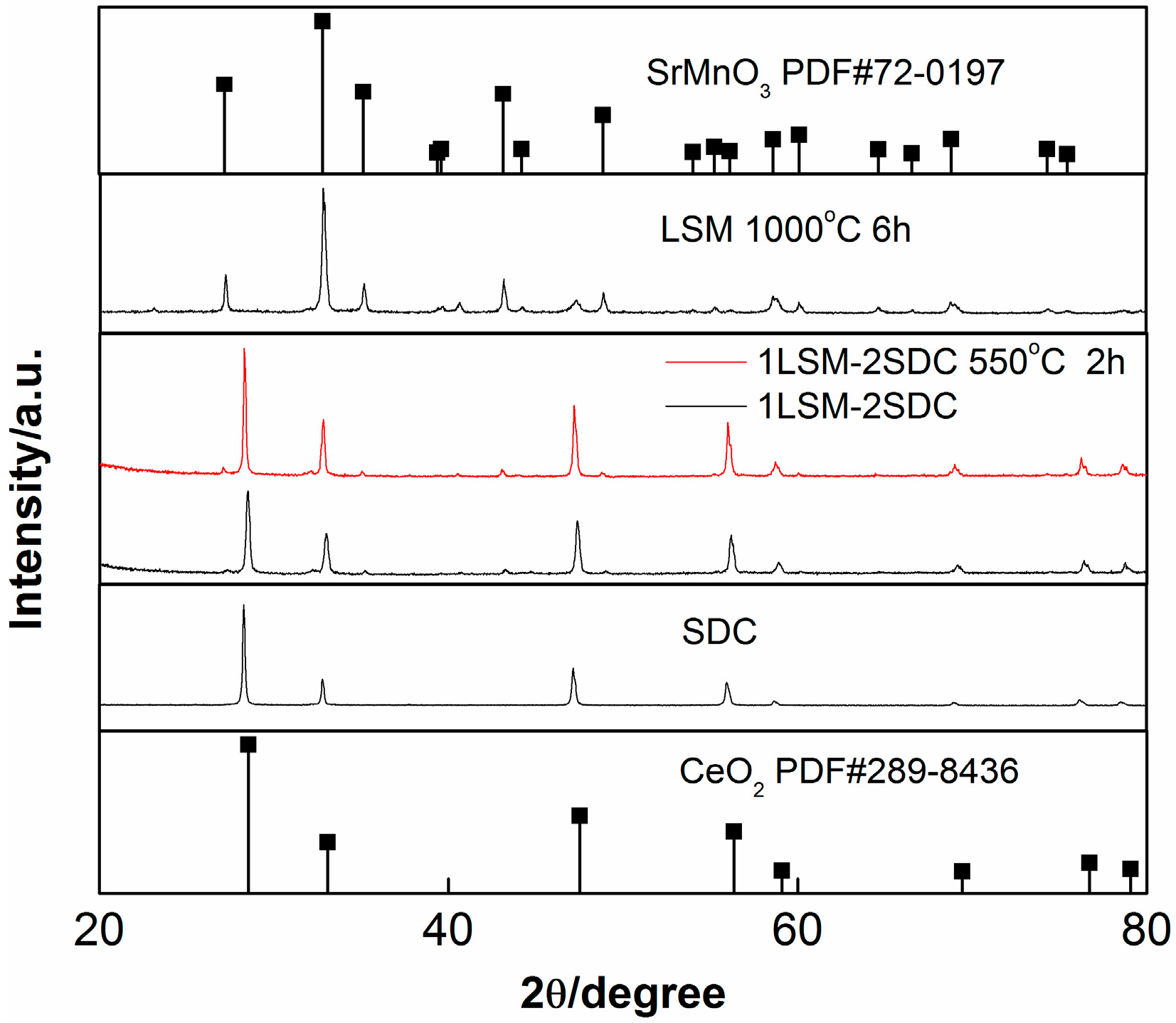
Figure 1. XRD patterns of LSM (La0.1Sr0.9MnO3−δ), SDC (Ce0.8Sm0.2O2−δ) and LSM-SDC composite before and after calciation treatment.
Materials 11 01549 g001
Figure 2. SEM of (a) LSM (La0.1Sr0.9MnO3−δ) material, (bd) original LSM-SDC (La0.1Sr0.9MnO3−δ-Ce0.8Sm0.2O2−δ) composite (1:2, wt:wt, without co-fire treatment), (ej) elemental mappings of the LSM-SDC composite (1:2, wt:wt). The elemental mappings were taken from Figure 2d.
Materials 11 01549 g002
Figure 3. Electrochemical performances (solid marks for I-V curves, empty marks for I-P curves) of SOFCs based on LSM-SDC (La0.1Sr0.9MnO3−δ-Ce0.8Sm0.2O2−δ) layer with various compositions.
Materials 11 01549 g003
Figure 4. Conductivities for LSM-SDC (La0.1Sr0.9MnO3−δ-Ce0.8Sm0.2O2−δ) composites with various compositions.
Materials 11 01549 g004
Figure 5. (a) I-V curves for the SOFCs with LSM-SDC (La0.1Sr0.9MnO3−δ-Ce0.8Sm0.2O2−δ) with weight ratio of 1:2. Scan rate: 50 mV/s; Test conditions: H2/air atmosphere (FC), air/air atmosphere (air), 550 oC; (b) Schematic of the Schottky junction in the fuel cell.
Materials 11 01549 g005
Figure 6. Arrhenius plots of ionic conductivity of LSM-SDC (La0.1Sr0.9MnO3−δ-Ce0.8Sm0.2O2−δ) composite (1:2, weight ratio) and pure SDC material.
Materials 11 01549 g006
Figure 7. (a) EIS of the LSM-SDC (La0.1Sr0.9MnO3−δ-Ce0.8Sm0.2O2−δ) composite series measured at 550 °C, OCV, fuel cell mode; points for experimental data, line for fitting data, (b) equivalent circuit.
Materials 11 01549 g007
Table 1. Fitting results of EIS data in Figure 7a.
ProportionRΩ (Ω·cm2)Ra (Ω·cm2)Rb (Ω·cm2)Rc (Ω·cm2)Rb + Rc (Ω·cm2)
Pure SDC0.110.0840.110.310.42
1LSM9SDC0.110.0600.0800.220.30
1LSM2SDC0.0900.0230.0960.210.31
1LSM1SDC0.100.0460.0950.220.31
3LSM1SDC0.100.0520.0740.230.31