Analysis of Failure Mechanics in Hybrid Fibre-Reinforced High-Performance Concrete Deep Beams with and without Openings


Abstract
:1. Introduction
2. Experimental Procedure/Process
2.1. Deep Beam Testing
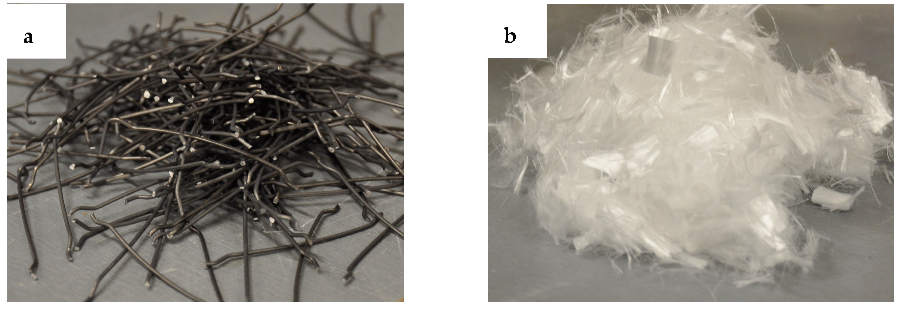
2.2. Material Properties
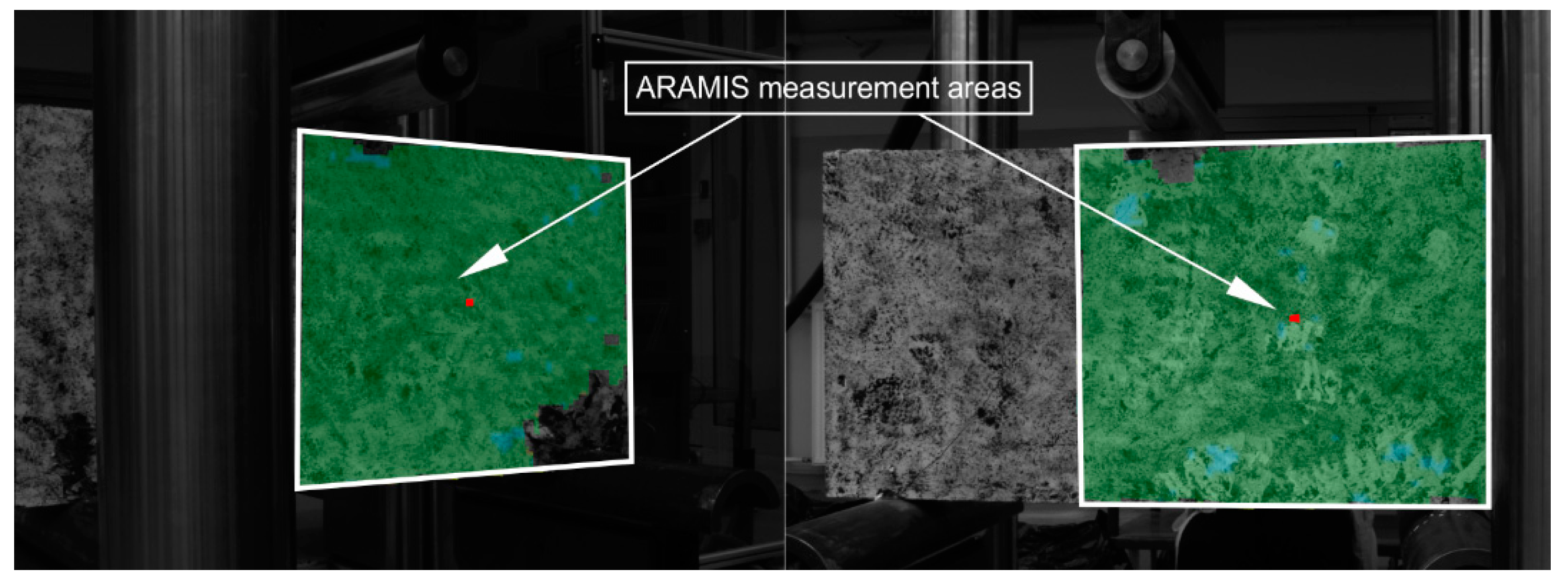
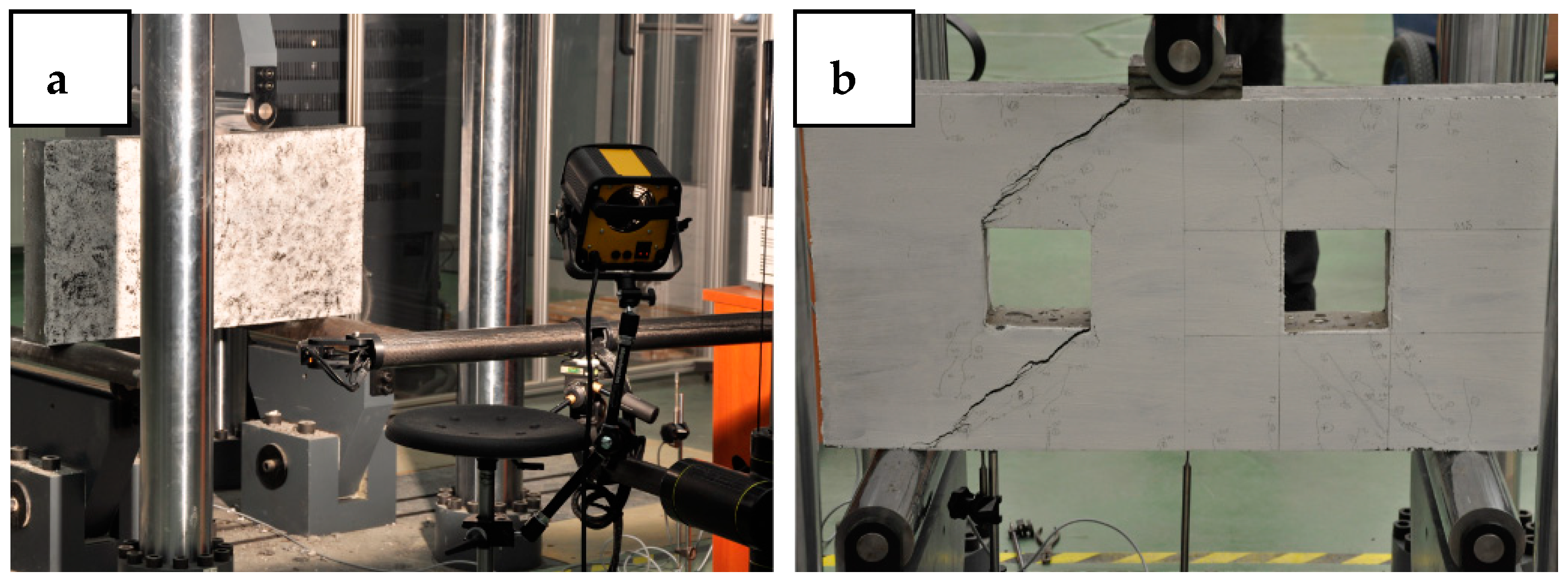
2.3. Testing Procedure
3. Experimental Results and Discussion
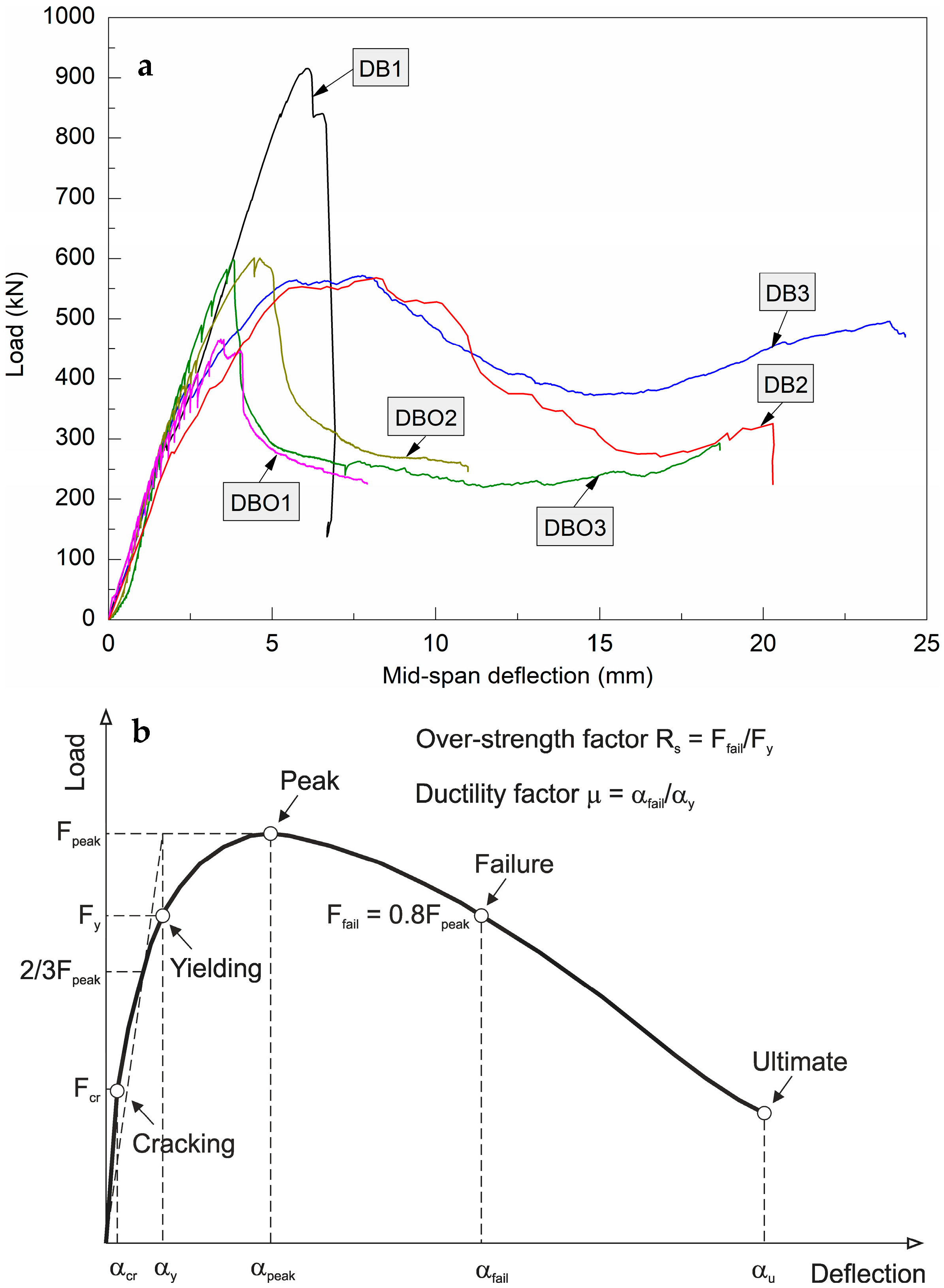
3.1. Load-Deflection Curves
3.2. Cracking Behaviour and Failure Modes
3.3. Parameters of Deep Beams
4. Analysis of Failure Modes
5. Conclusions
Funding
Conflicts of Interest
References
- Sivakumar, A.; Santhanam, M. Mechanical properties of high strength concrete reinforced with metallic and non-metallic fibres. Cem. Concr. Compos. 2007, 29, 603–608. [Google Scholar] [CrossRef]
- Choi, J.I.; Song, K.I.; Song, J.K.; Lee, B.Y. Composite properties of high-strength polyethylene fiber-reinforced cement and cementless composites. Compos. Struct. 2016, 138, 116–121. [Google Scholar] [CrossRef]
- Smarzewski, P. Effect of curing period on properties of steel and polypropylene fibre reinforced ultra-high performance concrete. IOP Conf. Ser. Mater. Sci. Eng. 2017, 245, 1–7. [Google Scholar] [CrossRef]
- Meng, W.; Yao, Y.; Mobasher, B.; Khayat, K.H. Effects of loading rate and notch-to-depth ratio of notched beams on flexural performance of ultra-high-performance concrete. Cem. Concr. Compos. 2017, 83, 349–359. [Google Scholar] [CrossRef]
- Smarzewski, P.; Barnat-Hunek, D. Property assessment of hybrid fiber-reinforced ultra-high-performance concrete. Int. J. Civ. Eng. 2018, 16, 593–606. [Google Scholar] [CrossRef]
- Brostow, W.; Hagg Lobland, H.E. Materials: Introduction and Applications; John Wiley & Sons: Hoboken, NJ, USA, 2017. [Google Scholar]
- Vandewalle, L.; Nemegeer, D.; Balazs, L.; DI PRISCO, M. Recommendations of RILEM TC 162-TDF: Test and design method for steel fibre reinforced concrete. Bending test. Mater. Struct. 2002, 35, 579–582. [Google Scholar]
- Vandewalle, L.; Nemegeer, D.; Balazs, L.; di Prisco, M. Final recommendations of RILEM TC 162-TDF: Test and design method for steel fibre reinforced concrete sigma-epsilon-design method. Mater. Struct. 2003, 36, 560–567. [Google Scholar]
- Guide for the design and construction of fiber-reinforced concrete structure. Available online: https://www.cnr.it/it/node/2640 (accessed on 28 December 2018).
- Shear and punching shear in RC and FRC elements. Available online: https://www.pci.org/PCI_Docs/Members_Only/Technical%20Resources/Fib%20Bulletin/fib_Bull57_NMG.pdf (accessed on 28 December 2018).
- Banthia, N.; Gupta, R. Hybrid fiber reinforced concrete (HyFRC): Fiber synergy in high strength matrices. Mater. Struct. 2004, 37, 707–716. [Google Scholar] [CrossRef]
- Brandt, A.M. Fibre reinforced cement-based (FRC) composites after over 40 years of development in building and civil engineering. Compos. Struct. 2008, 86, 3–9. [Google Scholar] [CrossRef]
- Brandt, A.M. Cement-based Composites: Materials, Mechanical Properties and Performance; CRC Press: London, UK, 2014. [Google Scholar]
- Foster, S.J. The application of steel-fibres as concrete reinforcement in Australia: from material to structure. Mater. Struct. 2009, 42, 1209–1220. [Google Scholar] [CrossRef]
- Walraven, J.C. High performance fibre reinforced concrete: progress in knowledge and design codes. Mater. Struct. 2009, 42, 1247–1260. [Google Scholar] [CrossRef]
- Prisco, M.; Plizzari, G.; Vandewalle, L. Fibre reinforced concrete: new design perspectives. Mater. Struct. 2009, 42, 1261–1281. [Google Scholar] [CrossRef]
- Parra-Montesinos, G.J.; Reinhardt, H.W. High Performance Fiber Reinforced Cement Composites 6; Naaman, A.E., Ed.; Springer: Berlin, Germany, 2012. [Google Scholar]
- Yoo, D.Y.; Yoon, Y.S. A Review on Structural Behavior, Design, and Application of Ultra-High-Performance Fiber-Reinforced Concrete. Int. J. Concr. Struct. M. 2016, 10, 125–142. [Google Scholar] [CrossRef] [Green Version]
- Dobiszewska, M. Waste materials used in making mortar and concrete. J. Mater. Ed. 2017, 39, 133–156. [Google Scholar]
- Chiaia, B.; Fantilli, A.P.; Vallini, P. Combining fibre-reinforced concrete with traditional reinforcement in tunnel linings. Eng. Struct. 2009, 31, 1600–1606. [Google Scholar] [CrossRef]
- Kang, S.-T.; Lee, K.-S.; Choi, J.-I.; Lee, Y.; Felekoglu, B.; Lee, B.Y. Control of tensile behavior of ultra-high performance concrete through artificial flaws and fiber hybridization. Int. J. Concr. Struct. M. 2016, 10, 33–41. [Google Scholar] [CrossRef]
- Smarzewski, P.; Barnat-Hunek, D. Effect of fiber hybridization on durability related properties of ultra-high performance concrete. Int. J. Concr. Struct. M. 2017, 11, 315–325. [Google Scholar] [CrossRef]
- Smarzewski, P. Flexural toughness of high-performance concrete with basalt and polypropylene short fibres. Adv. Civ. Eng. 2018, 2018, 1–8. [Google Scholar] [CrossRef]
- Smarzewski, P. Influence of basalt-polypropylene fibres on fracture properties of high performance concrete. Compos. Struct. 2019, 209, 23–33. [Google Scholar] [CrossRef]
- Smarzewski, P. Hybrid fibres as shear reinforcement in high-performance concrete beams with and without openings. Appl. Sci. 2018, 8, 2070. [Google Scholar] [CrossRef]
- ACI Committee. Building Code Requirements for Structural Concrete (ACI 318-08) and Commentary; American Concrete Institute: Farmington Hills, MI, USA, 2008. [Google Scholar]
- Leonhardt, F.; Mönning, E. Vorlesungen über Massivbau, teil.2, Sonderfalle der Bemessung im Stahlbetonbau; Springer: Berlin, Germany, 1975. [Google Scholar]
- Singh, R.; Ray, S.P.; Reddy, C.S. Some tests on reinforced concrete deep beams with and without opening in the web. Indian Concrete J. 1980, 54, 189–194. [Google Scholar]
- Foster, S.J.; Gilbert, R.I. Tests on High Strength Concrete Deep Beams; The University of New South Wales: Sydney, Australia, 1996. [Google Scholar]
- Kong, F.K. Reinforced Concrete Deep Beams; Kluwer Academic Pub.: Dordrecht, The Netherlands, 1990. [Google Scholar]
- Ashour, A.F.; Yang, K.H. Influence of Shear Reinforcement on Reinforced Concrete Continuous Deep Beams. ACI Struct. J. 2007, 104, 420–429. [Google Scholar] [CrossRef]
- Ashour, A.F.; Yang, K.H. Effectiveness of Web Reinforcement around Openings in Continuous Concrete Deep Beams. ACI Struct. J. 2008, 105, 414–424. [Google Scholar] [CrossRef]
- El Maaddawy, T.; Sherif, S. FRP composites for shear strengthening of reinforced concrete deep beams with openings. Compos. Struct. 2009, 89, 60–69. [Google Scholar] [CrossRef]
- Arabzadeh, A.; Aghayari, R.; Rahai, A.R. Investigation of Experimental and Analitical Shear Strength of Reinforced Concrete Deep Beams. Int. J. Civ. Struct. Eng. 2011, 9, 207–214. [Google Scholar] [CrossRef]
- Gedik, Y.H.; Nakamura, H.; Yamamoto, Y.; Ueda, N.; Kunieda, M. Effect of Stirrups on the Shear Failure Mechanism of Deep Beams. J. Adv. Concr. Tech. 2012, 10, 14–30. [Google Scholar] [CrossRef] [Green Version]
- Kopańska, A.; Nagrodzka-Godycka, K. The influence of reinforcement on load carrying capacity and cracking of the reinforced concrete deep beam joint. Eng. Struct. 2016, 107, 23–33. [Google Scholar] [CrossRef]
- ACI Committee. Report on Fiber Reinforced Concrete (ACI 544.1R-96) (Reapproved 2009); American Concrete Institute: Farmington Hills, MI, USA, 1996. [Google Scholar]
- Sahoo, D.R.; Flores, C.A.; Chao, S.-H. Behavior of steel fiber-reinforced concrete deep beams with large opening. ACI Struct. J. 2012, 109, 193–203. [Google Scholar] [CrossRef]
- Dazio, A.; Buzzini, D.; Trüb, M. Nonlinear cyclic behaviour of Hybrid Fibre Concrete structural walls. Eng. Struct. 2008, 30, 3141–3150. [Google Scholar] [CrossRef]
- Vengatachalapathy, V.; Ilangovan, R. A study on steel fibre reinforced concrete deep beams with and without openings. Int. J. Civ. Struct. Eng. 2010, 1, 509–517. [Google Scholar]
- Ma, K.; Qi, T.; Liu, H.; Wang, H. Shear behavior of hybrid fiber reinforced concrete deep beams. Materials 2018, 11, 2023. [Google Scholar] [CrossRef] [PubMed]
- Kolesov, A.E.; Sivtsev, P.V.; Smarzewski, P.; Vabishchevich, P.N. Numerical Analysis of Reinforced Concrete Deep Beams. In Proceedings of the International Conference on Numerical Analysis and Its Applications, Lotzenetz, Bulgaria, 15–22 June 2016; pp. 414–421. [Google Scholar]
- Naaman, A.E.; Najm, H. Bond-slip mechanisms of steel fibres in concrete. ACI Mat. J. 1991, 88, 135–145. [Google Scholar] [CrossRef]
- Yan, H.; Sun, W.; Chen, H. The effect of silica fume and steel fiber on the dynamic mechanical performance of high-strength concrete. Cem. Concr. Res. 1999, 29, 423–426. [Google Scholar] [CrossRef]
- Banthia, N.; Nandakumar, N. Crack growth resistance of hybrid fiber reinforced cement composites. Cem. Concr. Compos. 2003, 25, 3–9. [Google Scholar] [CrossRef]
- Martinez-Barrera, G.; Vigueras-Santiago, E.; Hernandez-Lopez, S.; Menchaca-Campos, C.; Brostow, W. Mechanical improvement of concrete by irradiated polypropylene fibers. Polymer Eng. Sci. 2005, 45, 1426–1431. [Google Scholar] [CrossRef]
- Martínez-Barrera, G.; Ureña-Nuñez, F.; Gencel, O.; Brostow, W. Mechanical properties of polypropylene-fiber reinforced concrete after gamma irradiation. Compos. Part A 2011, 42, 567–572. [Google Scholar] [CrossRef]
- PN-EN 933-1: Tests for geometrical properties of aggregates. Determination of particle size distribution. Sieving method. Available online: http://sklep.pkn.pl/pn-en-933-1-2012e.html (accessed on 31 October 2018).
- PN-EN 12390-3. Testing Hardened Concrete. Compressive Strength of Test Specimens. Available online: http://sklep.pkn.pl/pn-en-12390-3-2011p.html (accessed on 31 October 2018).
- PN-EN 12390-6. Testing Hardened Concrete. Tensile Splitting Strength of Test Specimens. Available online: http://sklep.pkn.pl/pn-en-12390-6-2011p.html (accessed on 31 October 2018).
- PN-EN 12390-5. Testing Hardened Concrete. Flexural Strength of Test Specimens. Available online: http://sklep.pkn.pl/pn-en-12390-5-2011p.html (accessed on 31 October 2018).
- ASTM C469/C469M-14. Standard Test Method for Static Modulus of Elasticity and Poisson’s Ratio of Concrete in Compression; ASTM International: West Conshohocken, PA, USA, 2014. [Google Scholar] [CrossRef]
- Ramakrishnan, V.; Wu, G.Y.; Hosalli, G. Flexural fatigue strength, endurance limit, and impact strength of fiber reinforced concretes. Transport. Res. Rec. 1989, 1226, 17–24. [Google Scholar]
- Vondran, G.L.; Nagabhushanam, M.; Ramakrishnan, V. Fatigue Strength of Polypropylene Fiber Reinforced Concretes, Fiber Reinforced Cements and Concretes: Recent Developments; Swamy, R.N., Barr, B., Eds.; Elsevier Applied Science: London, UK, 1990; pp. 533–543. [Google Scholar]
- Mohammadi, Y.; Singh, S.P.; Kaushik, S.K. Properties of steel fibrous concrete containing mixed fibres in fresh and hardened state. Constr. Build. Mater. 2008, 22, 956–965. [Google Scholar] [CrossRef]
- Qian, C.X.; Stroeven, P. Development of hybrid polypropylene-steel fibre-reinforced concrete. Cem. Concr. Res. 2000, 30, 63–69. [Google Scholar] [CrossRef]
- Afroughsabet, V.; Biolzi, L.; Ozbakkaloglu, T. High-performance fiber-reinforced concrete: a review. J. Mater. Sci. 2016, 51, 6517–6551. [Google Scholar] [CrossRef]
- PN-B-03264. Plain, reinforced and prestressed concrete structures—Analysis and structural design. Available online: http://sklep.pkn.pl/pn-b-03264-2002p.html (accessed on 10 December 2018).
- ARAMIS v6.3: User Manual—Software; GOM mbH: Braunschweig, Germany, 2007.
- Rashid, M.; Mansur, M. Reinforced high-strength concrete beams in flexure. ACI Struct. J. 2005, 102, 462–471. [Google Scholar] [CrossRef]
- Pan, A.; Moehle, J.P. Lateral displacement ductility of reinforced concrete flat plates. ACI Struct. J. 1989, 86, 250–258. [Google Scholar] [CrossRef]
- Lim, W.-Y.; Hong, S.-G. Shear tests for ultra-high performance fiber reinforced concrete (UHPFRC) beams with shear reinforcement. Int. J. Concr. Struct. M. 2016, 10, 177–188. [Google Scholar] [CrossRef]
- Mitchell, D.; Paultre, P. Ductility and overstrength in seismic design of reinforced concrete structures. Can. J. Civil. Eng. 1994, 21, 1049–1060. [Google Scholar] [CrossRef]
- Banthia, N.; Sappakittipakorn, M. Toughness enhancement in steel fiber reinforced concrete through fiber hybridization. Cem. Concr. Res. 2007, 37, 1366–1372. [Google Scholar] [CrossRef]


| Material | Symbol Unit | DB1 | DB2 | DB3 | DBO1 | DBO2 | DBO3 |
|---|---|---|---|---|---|---|---|
| Cement CEM I 52.5R | C (kg/m3) | 596 | 596 | 596 | 596 | 596 | 596 |
| Silica fume | M (kg/m3) | 149 | 149 | 149 | 59.6 | 59.6 | 59.6 |
| Granodiorite 2/8 mm | A (kg/m3) | 990 | 990 | 990 | 990 | 990 | 990 |
| Quartz sand 0.05/2 mm | S (kg/m3) | 500 | 500 | 500 | 500 | 500 | 500 |
| Superplasticiser | SP (l/m3) | 39 | 39 | 39 | 20 | 20 | 20 |
| Water | W (l/m3) | 139 | 139 | 139 | 177 | 177 | 177 |
| Steel fibre | ST (kg/m3) | - | 78 | 156 | - | 78 | 117 |
| VST (%) | - | 1 | 2 | - | 1 | 1.5 | |
| Polypropylene fibre | PP (kg/m3) | - | 2.3 | 4.5 | - | 0.5 | 1 |
| VPP (%) | - | 0.25 | 0.5 | - | 0.05 | 0.1 |
| Concrete Properties | Unit | DB1 | DB2 | DB3 | DBO1 | DBO2 | DBO3 |
|---|---|---|---|---|---|---|---|
| Compressive strength | MPa | 114.2 | 88.1 | 84.7 | 113.0 | 113.6 | 112.4 |
| Splitting tensile strength | 5.3 | 6.9 | 7.4 | 6.2 | 10.2 | 10.4 | |
| Flexural tensile strength | 6.9 | 8.9 | 8.3 | 7.4 | 8.7 | 9.1 | |
| Modulus of elasticity | 38741 | 39598 | 39370 | 38251 | 38964 | 39131 |
| Reinforcement | Diameter (mm) | Yield Strength (MPa) | Tensile Strength (MPa) | Ultimate Elongation (%) | Modulus of Elasticity (GPa) |
|---|---|---|---|---|---|
| Tension bar | 22 | 457 | 644 | 10.5 | 203 |
| Compression and diagonal bar | 12 | 456 | 642 | 9.7 | 199 |
| Web mesh | 8 | 447 | 640 | 9.6 | 196 |
| Stirrup | 6 | 302 | 454 | 8.5 | 193 |
| Deep Beam Notation | Fibre Volume Content (%) | Cracking | Yielding | Peak | Failure | ||||
|---|---|---|---|---|---|---|---|---|---|
| Load Fcr (kN) | Deflection αcr (mm) | Load Fy (kN) | Deflection αy (mm) | Load Fpeak (kN) | Deflection αpeak (mm) | Load Ffail (kN) | Deflection αfail (mm) | ||
| DB1 | - | 280 | 1.7 | 891 | 5.7 | 915 | 6.1 | 732 | 6.7 |
| DB2 | 1 ST + 0.25 PP | 270 | 1.9 | 442 | 3.9 | 566 | 8.2 | 453 | 11.1 |
| DB3 | 2 ST + 0.5 PP | 380 | 2.5 | 453 | 3.5 | 571 | 7.8 | 457 | 11.0 |
| DBO1 | - | 130 | 0.7 | 412 | 2.9 | 466 | 3.4 | 373 | 4.1 |
| DBO2 | 1 ST + 0.05 PP | 140 | 0.9 | 546 | 3.7 | 601 | 4.5 | 481 | 5.2 |
| DBO3 | 1.5 ST + 0.1 PP | 150 | 1.1 | 560 | 3.4 | 598 | 3.8 | 479 | 3.9 |
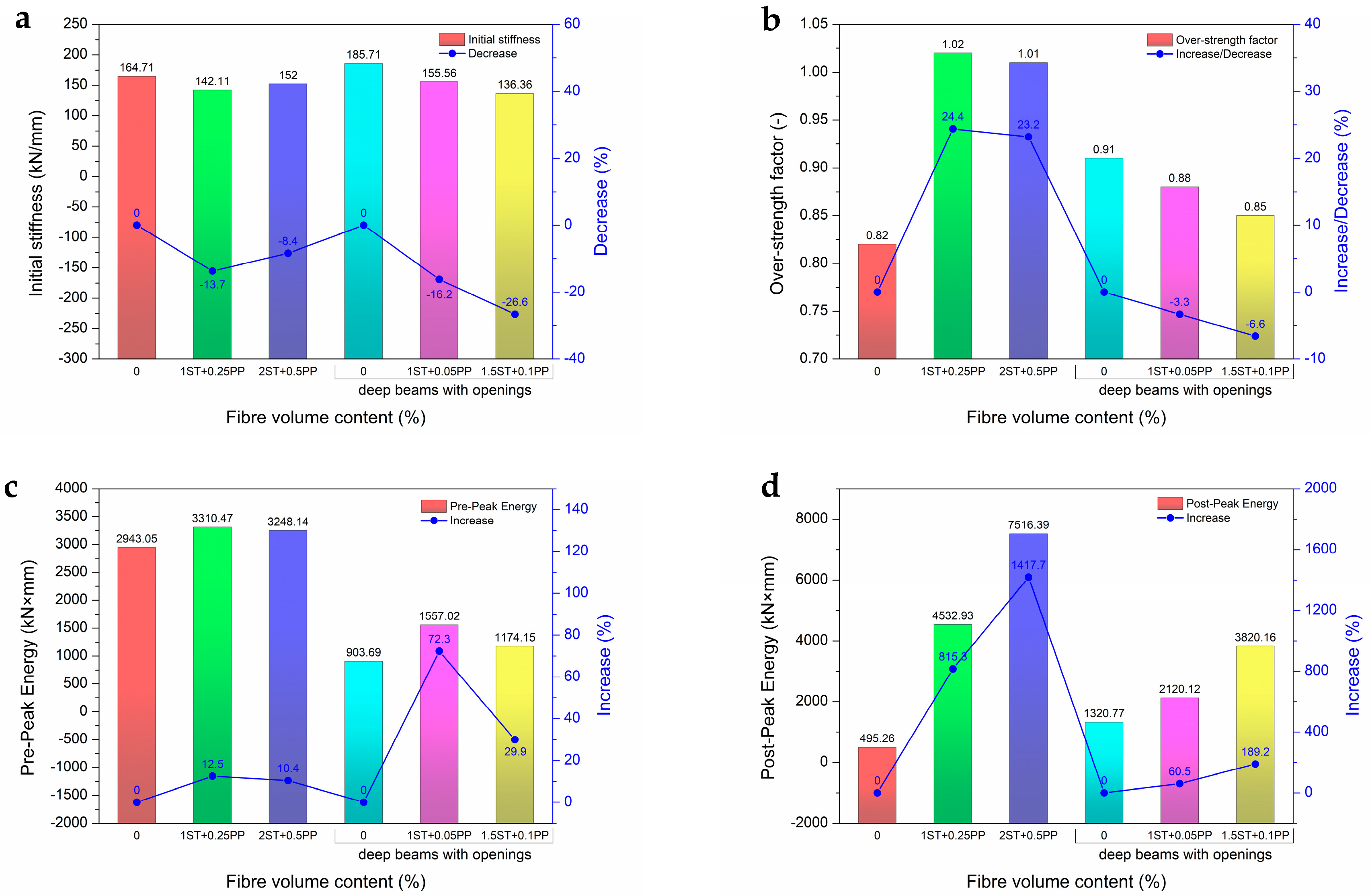
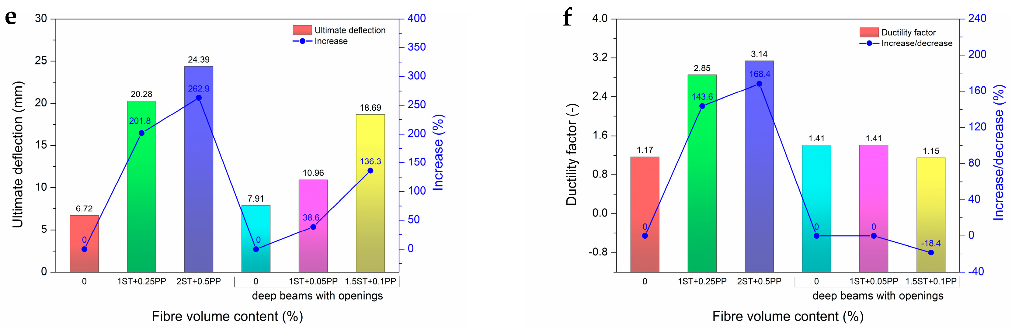
| Deep Beam Notation | Fibre Volume Content (%) | Initial Stiffness (kN/mm) | Over-Strength Factor (–) | Pre-Peak Energy (kN × mm) | Post-Peak Energy (kN × mm) | Ductility Factor (–) |
|---|---|---|---|---|---|---|
| DB1 | - | 165 | 0.82 | 2943 | 495 | 1.17 |
| DB2 | 1 ST + 0.25 PP | 142 | 1.02 | 3310 | 4533 | 2.85 |
| DB3 | 2 ST + 0.5 PP | 152 | 1.01 | 3248 | 7516 | 3.14 |
| DBO1 | - | 186 | 0.91 | 904 | 1321 | 1.41 |
| DBO2 | 1 ST + 0.05 PP | 156 | 0.88 | 1557 | 2120 | 1.41 |
| DBO3 | 1.5 ST + 0.1 PP | 136 | 0.85 | 1174 | 3820 | 1.15 |
| Deep Beam | Experimental Vexp (kN) | Analytical | Ratio Vexp/Vanl | ||
|---|---|---|---|---|---|
| Vs (kN) | Vc (kN) | Vanl (kN) | |||
| DB1 | 915.4 | 549.2 | 359.3 | 908.5 | 1.01 |
| DB2 | 566.0 | 158.8 | 426.4 | 585.2 | 0.97 |
| DB3 | 571.3 | 146.4 | 447.9 | 594.3 | 0.96 |
| DBO1 | 466.2 | 140.9 | 426.5 | 567.4 | 0.82 |
| DBO2 | 600.8 | 295.2 | 211.9 | 507.1 | 1.18 |
| DBO3 | 598.3 | 289.7 | 214.8 | 504.5 | 1.19 |
© 2018 by the author. Licensee MDPI, Basel, Switzerland. This article is an open access article distributed under the terms and conditions of the Creative Commons Attribution (CC BY) license (http://creativecommons.org/licenses/by/4.0/).
Share and Cite
Smarzewski, P. Analysis of Failure Mechanics in Hybrid Fibre-Reinforced High-Performance Concrete Deep Beams with and without Openings. Materials 2019, 12, 101. https://doi.org/10.3390/ma12010101
Smarzewski P. Analysis of Failure Mechanics in Hybrid Fibre-Reinforced High-Performance Concrete Deep Beams with and without Openings. Materials. 2019; 12(1):101. https://doi.org/10.3390/ma12010101
Chicago/Turabian StyleSmarzewski, Piotr. 2019. "Analysis of Failure Mechanics in Hybrid Fibre-Reinforced High-Performance Concrete Deep Beams with and without Openings" Materials 12, no. 1: 101. https://doi.org/10.3390/ma12010101