Alumina Coated Silica Nanosprings (NS) Support Based Cobalt Catalysts for Liquid Hydrocarbon Fuel Production From Syngas

 ,
, 
Abstract
:
1. Introduction
2. Experimental Methods
2.1. Preparation of Catalysts
2.2. Characterization of As-Prepared Catalysts
2.3. Catalytic Activation and FTS Evaluation
3. Results and Discussion
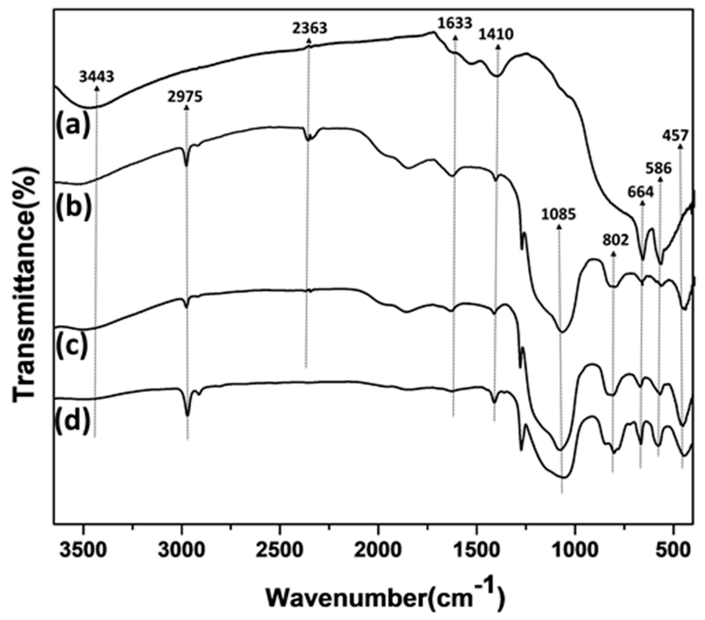
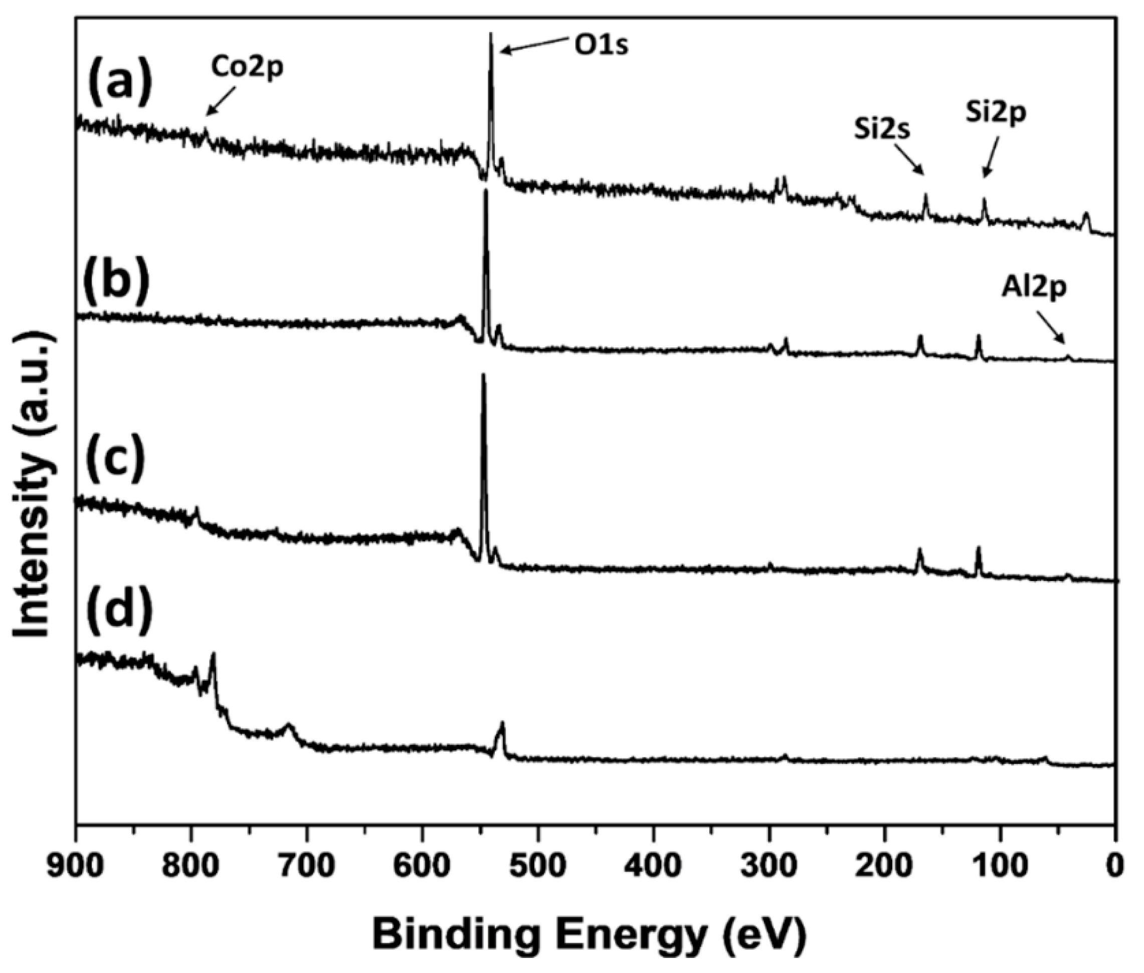
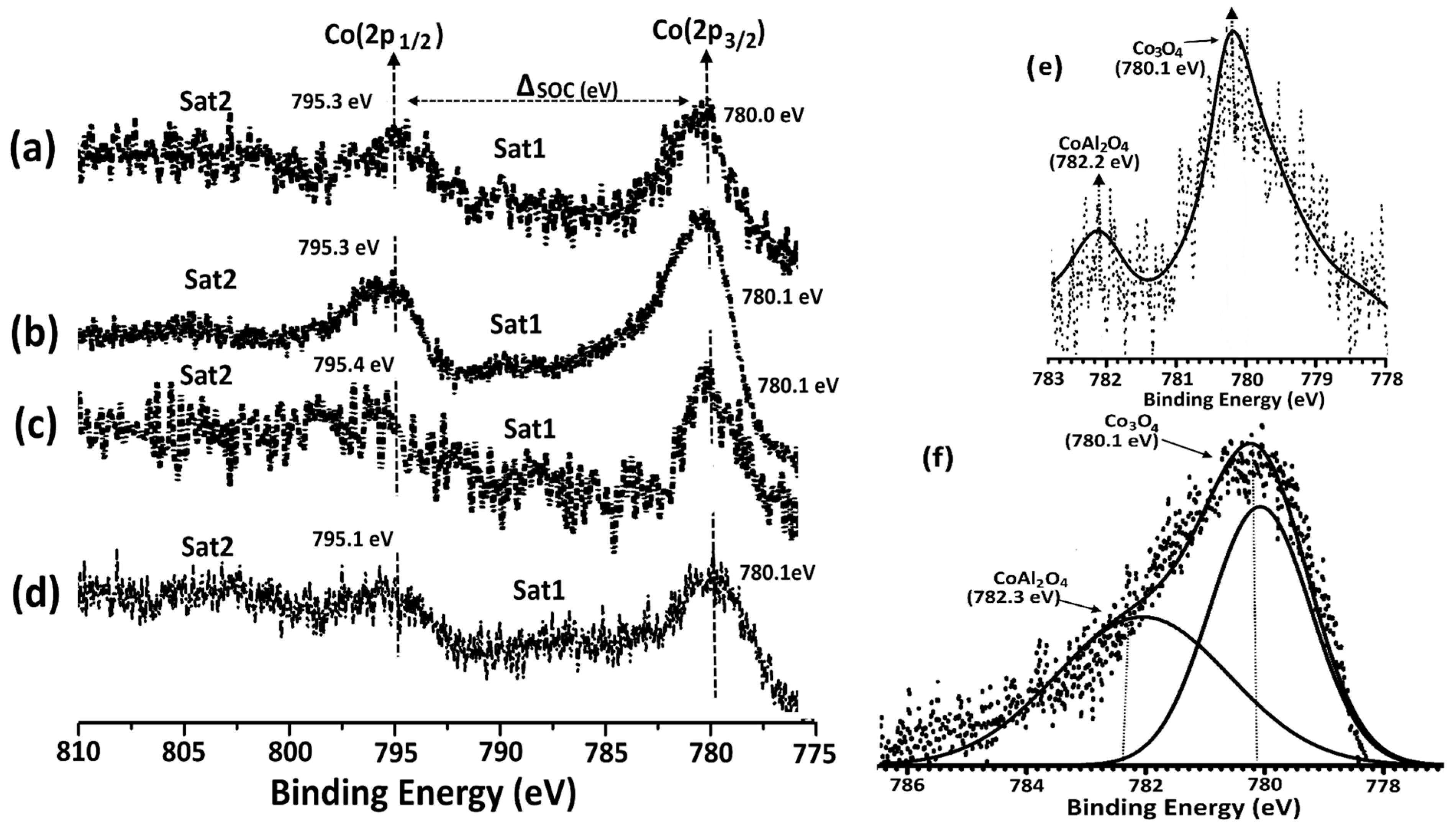
3.1. Catalyst Preparation and Characterization
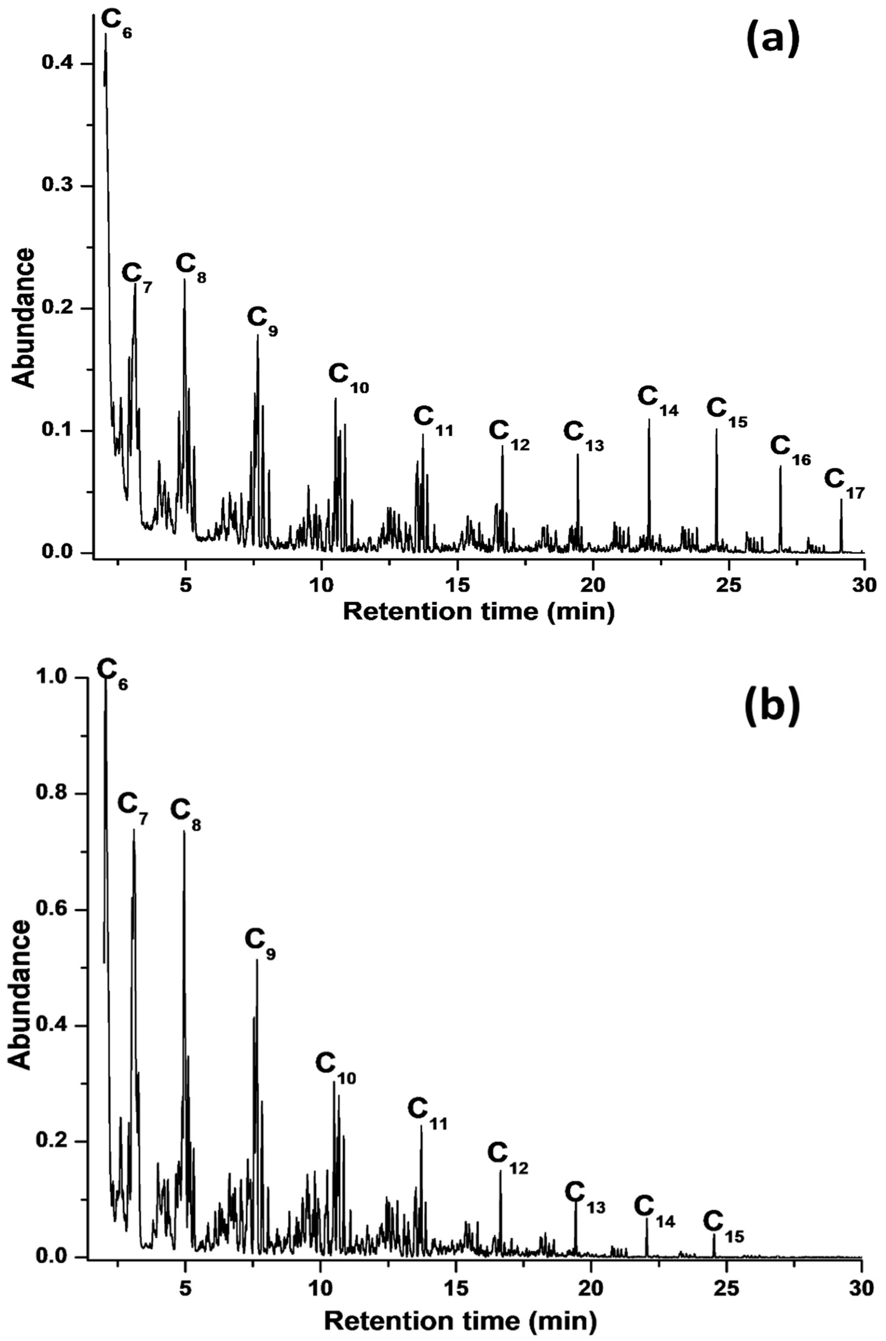
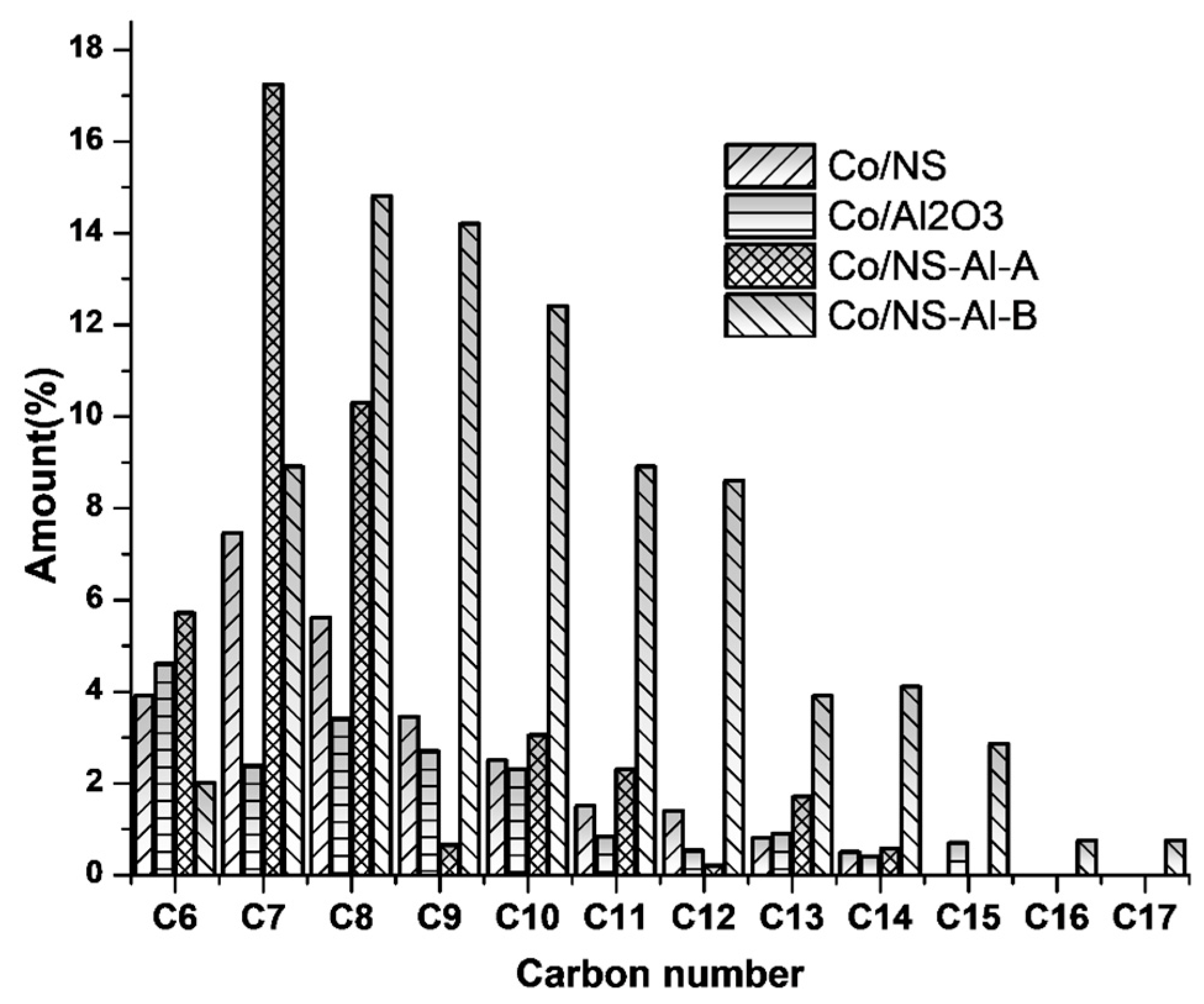
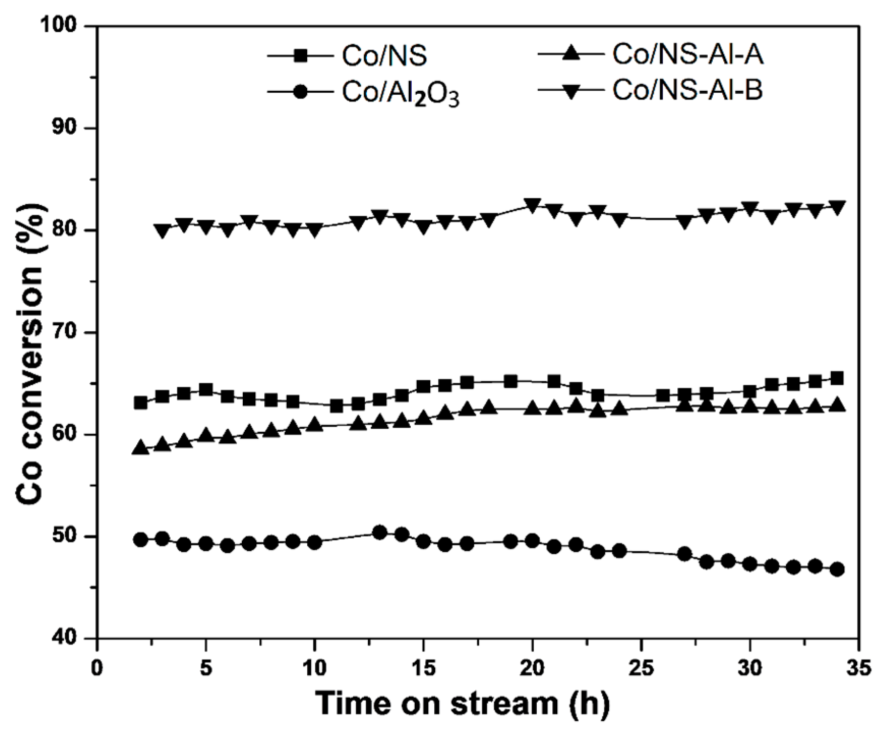
3.2. Catalytic Activity Testing
4. Conclusions
Supplementary Materials
Author Contributions
Acknowledgments
Conflicts of Interest
References
- Alayat, A.; Mcllroy, D.; McDonald, A.G. Effect of synthesis and activation methods on the catalytic properties of silica nanospring (NS)-supported iron catalyst for Fischer-Tropsch synthesis. Fuel Process. Technol. 2018, 169, 132–141. [Google Scholar] [CrossRef]
- Kengne, B.-A.F.; Alayat, A.M.; Luo, G.; McDonald, A.G.; Brown, J.; Smotherman, H.; McIlroy, D.N. Preparation, surface characterization and performance of a Fischer-Tropsch catalyst of cobalt supported on silica nanosprings. Appl. Surf. Sci. 2015, 359, 508–514. [Google Scholar] [CrossRef]
- Bao, A.; Liew, K.; Li, J. Fischer-Tropsch synthesis on CaO-promoted Co/Al2O3 catalysts. J. Mol. Catal. A Chem. 2009, 304, 47–51. [Google Scholar] [CrossRef]
- Alayat, A.; Echeverria, E.; Mcllroy, D.N.; McDonald, A.G. Enhancement of the catalytic performance of silica nanosprings (NS)-supported iron catalyst with copper, molybdenum, cobalt and ruthenium promoters for Fischer-Tropsch synthesis. Fuel Process. Technol. 2018, 177, 89–100. [Google Scholar] [CrossRef]
- Savost’yanov, A.P.; Yakovenko, R.E.; Sulima, S.I.; Bakun, V.G.; Narochnyi, G.B.; Chernyshev, V.M.; Mitchenko, S.A. The impact of Al2O3 promoter on an efficiency of C5+ hydrocarbons formation over Co/SiO2 catalysts via Fischer-Tropsch synthesis. Catal. Today 2017, 279, 107–114. [Google Scholar] [CrossRef]
- Zhang, Y.; Nagamori, S.; Hinchiranan, S.; Vitidsant, T.; Tsubaki, N. Promotional effects of Al2O3 addition to Co/SiO2 catalysts for Fischer-Tropsch synthesis. Energy Fuels 2006, 20, 417–421. [Google Scholar] [CrossRef]
- Prasongthum, N.; Reubroycharoen, P. Preparation of Co/SiO2-Al2O3 Fiber Catalyst by Electrospinning for Fischer-Tropsch Synthesis. Key Eng. Mater. 2015, 659, 221. [Google Scholar] [CrossRef]
- Heidarinasab, A.; Soltanieh, M.; Ardjmand, M.; Ahmadpanahi, H.; Bahmani, M. Comparison of Mo/MgO and Mo/γ-Al2O3 catalysts: Impact of support on the structure and dibenzothiophene hydrodesulfurization reaction pathways. Int. J. Environ. Sci. Technol. 2016, 13, 1065–1076. [Google Scholar] [CrossRef]
- Luo, G.; Fouetio Kengne, B.A.; McIlroy, D.N.; McDonald, A.G. A novel nano fischer-tropsch catalyst for the production of hydrocarbons. Environ. Prog. Sustain. Energy 2014, 33, 693–698. [Google Scholar] [CrossRef]
- Ji, L.; Lin, J.; Tan, K.; Zeng, H. Synthesis of high-surface-area alumina using aluminum tri-sec-butoxide−2, 4-pentanedione−2-propanol− nitric acid precursors. Chem. Mater. 2000, 12, 931–939. [Google Scholar] [CrossRef]
- Ahmadipour, M.; Hatami, M.; Rao, K.V. Preparation and characterization of nano-sized (Mg(x)Fe(1–x)O/SiO2)(x = 0.1) core-shell nanoparticles by chemical precipitation method. Adv. Nanopart. 2012, 1, 37. [Google Scholar] [CrossRef]
- Hao, Q.-Q.; Zhao, Y.-H.; Yang, H.-H.; Liu, Z.-T.; Liu, Z.-W. Alumina grafted to SBA-15 in supercritical CO2 as a support of cobalt for Fischer-Tropsch synthesis. Energy Fuels 2012, 26, 6567–6575. [Google Scholar] [CrossRef]
- Zhao, Y.-H.; Song, Y.-H.; Hao, Q.-Q.; Wang, Y.-J.; Wang, W.; Liu, Z.-T.; Zhang, D.; Liu, Z.-W.; Zhang, Q.-J.; Lu, J. Cobalt-supported carbon and alumina co-pillared montmorillonite for Fischer-Tropsch synthesis. Fuel Process. Technol. 2015, 138, 116–124. [Google Scholar] [CrossRef]
- Alayat, A.M.; Echeverria, E.; Mcllroy, D.N.; McDonald, A.G. Characterization and catalytic behavior of EDTA modified silica nanosprings (NS)-supported cobalt catalyst for Fischer-Tropsch CO-hydrogenation. J. Fuel Chem. Technol. 2018, 46, 957–966. [Google Scholar] [CrossRef]
- Trotte, N.S.; Aben-Athar, M.T.; Carvalho, N.M. Yerba Mate Tea Extract: A Green Approach for the Synthesis of Silica Supported Iron Nanoparticles for Dye Degradation. J. Braz. Chem. Soc. 2016, 27, 2093–2104. [Google Scholar] [CrossRef]
- Rafiee, H.R.; Feyzi, M.; Jafari, F.; Safari, B. Preparation and Characterization of Promoted Fe-V/SiO2 Nanocatalysts for Oxidation of Alcohols. J. Chem. 2013, 2013, 412308. [Google Scholar] [CrossRef]
- Nuernberg, G.B.; Fajardo, H.V.; Mezalira, D.Z.; Casarin, T.J.; Probst, L.F.; Carreño, N.L. Preparation and evaluation of Co/Al2O3 catalysts in the production of hydrogen from thermo-catalytic decomposition of methane: Influence of operating conditions on catalyst performance. Fuel 2008, 87, 1698–1704. [Google Scholar] [CrossRef]
- Saraswat, S.K.; Pant, K. Progressive Loading Effect of Co Over SiO2/Al2O3 Catalyst for Cox Free Hydrogen and Carbon Nanotubes Production Via Catalytic Decomposition of Methane. Progressive 2015, 1, 59674. [Google Scholar]
- Lee, G.-Y.; Ryu, K.-H.; Kim, H.-G.; Kim, Y.-Y. The Preparation of Blue CoAl2O4 Powders by the Malonate Method: The Effect of the Amount of Malonic Acid Used, the Formation Pathway of CoAl2O4 Crystallites and the Characteristics of the Prepared Powders. Bull. Korean Chem. Soc. 2009, 30, 373–377. [Google Scholar]
- Moghanian, H.; Mobinikhaledi, A.; Blackman, A.; Sarough-Farahani, E. Sulfanilic acid-functionalized silica-coated magnetite nanoparticles as an efficient, reusable and magnetically separable catalyst for the solvent-free synthesis of 1-amido-and 1-aminoalkyl-2-naphthols. RSC Adv. 2014, 4, 28176–28185. [Google Scholar] [CrossRef]
- Nabid, M.R.; Bide, Y.; Abuali, M. Copper core silver shell nanoparticle–yolk/shell Fe3O4@ chitosan-derived carbon nanoparticle composite as an efficient catalyst for catalytic epoxidation in water. RSC Adv. 2014, 4, 35844–35851. [Google Scholar] [CrossRef]
- Ji, L.; Tang, S.; Chen, P.; Zeng, H.; Lin, J.; Tan, K. Effect of nanostructured supports on catalytic methane decomposition. Pure Appl. Chem. 2000, 72, 327–331. [Google Scholar] [CrossRef] [Green Version]
- De Beer, M.; Kunene, A.; Nabaho, D.; Claeys, M.; Van Steen, E. Technical and economic aspects of promotion of cobalt-based Fischer-Tropsch catalysts by noble metals-a review. J. S. Afr. Inst. Min. Metall. 2014, 114, 157–165. [Google Scholar]
- Zhang, J.; Chen, J.; Li, Y.; Sun, Y. Recent technological developments in cobalt catalysts for Fischer-Tropsch synthesis. J. Nat. Gas Chem. 2002, 11, 99–108. [Google Scholar]
- Rohr, F.; Lindvåg, O.; Holmen, A.; Blekkan, E.A. Fischer-Tropsch synthesis over cobalt catalysts supported on zirconia-modified alumina. Catal. Today 2000, 58, 247–254. [Google Scholar] [CrossRef]


| Catalysts | Al (wt.%) | Co (wt.%) | SBET (m2 g−1) | Size of Co3O4 Particles (nm) | dXRD (Co0) (nm) | Co Dispersion (%) | |
|---|---|---|---|---|---|---|---|
| dXRD | dTEM | ||||||
| NS | - | - | 314 | - | - | - | - |
| Al2O3 | - | - | 227 | - | - | - | - |
| Co/NS | - | 15 | 193 | 9.8 | 6.6 | 7.3 | 13.1 |
| Co/Al2O3 | 85 | 15 | 108 | 12.2 | 10.8 | 9.1 | 10.5 |
| Co/NS-Al-A Co/NS-Al-B | 8 8 | 15 15 | 199 260 | 10.6 8.1 | 8.2 5.7 | 7.8 6.0 | 12.3 16.0 |
| Catalyst | Co/NS | Co/Al2O3 | Co/NS-Al-A | Co/NS-Al-B |
|---|---|---|---|---|
| CO Conversion (%) | 65.5 | 46.8 | 62.8 | 82.4 |
| H2 Conversion (%) | 61.2 | 39.7 | 56.2 | 73.3 |
| Products Selectivity (%) | ||||
| CO2 select. (%) | 5.3 | 17.4 | 8.7 | 0.6 |
| CH4 select. (%) | 6.7 | 20.4 | 10.6 | 7.7 |
| Σ < C5 | 17.1 | 29.6 | 21.0 | 5.4 |
| Product distribution (Mol. %) | ||||
| Σ > C6 | 70.9 | 32.6 | 58.5 | 86.3 |
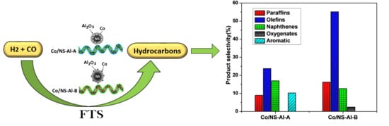
| Paraffins | 18.4 | 5.8 | 8.9 | 16.2 |
| Olefins | 26.6 | 13.6 | 23.7 | 55.1 |
| Naphthenes | 17.3 | 8.6 | 16.9 | 12.6 |
| Oxygenates | 8.6 | 4.6 | - | 2.4 |
| Aromatics | - | - | 10.2 | - |
| Olefins /Paraffins (O/P) | 1.44 | 2.34 | 2.66 | 3.40 |
© 2019 by the authors. Licensee MDPI, Basel, Switzerland. This article is an open access article distributed under the terms and conditions of the Creative Commons Attribution (CC BY) license (http://creativecommons.org/licenses/by/4.0/).
Share and Cite
Alayat, A.; Echeverria, E.; Sotoudehniakarani, F.; Mcllroy, D.N.; McDonald, A.G. Alumina Coated Silica Nanosprings (NS) Support Based Cobalt Catalysts for Liquid Hydrocarbon Fuel Production From Syngas. Materials 2019, 12, 1810. https://doi.org/10.3390/ma12111810
Alayat A, Echeverria E, Sotoudehniakarani F, Mcllroy DN, McDonald AG. Alumina Coated Silica Nanosprings (NS) Support Based Cobalt Catalysts for Liquid Hydrocarbon Fuel Production From Syngas. Materials. 2019; 12(11):1810. https://doi.org/10.3390/ma12111810
Chicago/Turabian StyleAlayat, Abdulbaset, Elena Echeverria, Farid Sotoudehniakarani, David N. Mcllroy, and Armando G. McDonald. 2019. "Alumina Coated Silica Nanosprings (NS) Support Based Cobalt Catalysts for Liquid Hydrocarbon Fuel Production From Syngas" Materials 12, no. 11: 1810. https://doi.org/10.3390/ma12111810
APA StyleAlayat, A., Echeverria, E., Sotoudehniakarani, F., Mcllroy, D. N., & McDonald, A. G. (2019). Alumina Coated Silica Nanosprings (NS) Support Based Cobalt Catalysts for Liquid Hydrocarbon Fuel Production From Syngas. Materials, 12(11), 1810. https://doi.org/10.3390/ma12111810