Investigation of the Joining Technology of FRP/AZ31B Magnesium Alloy by Welding and Riveting Hybrid Bonding Method

Abstract
:
1. Introduction
2. Materials and Method
3. Results and Discussion
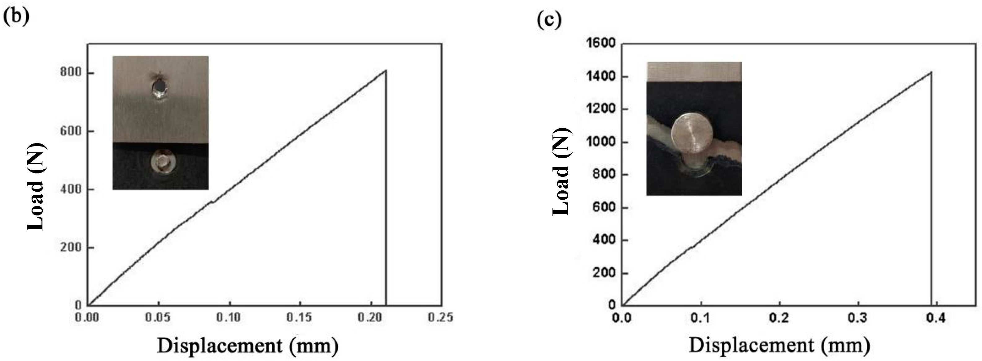
3.1. Weld Seam and Property
3.2. Microstructure of the Hybrid Bonding Joint
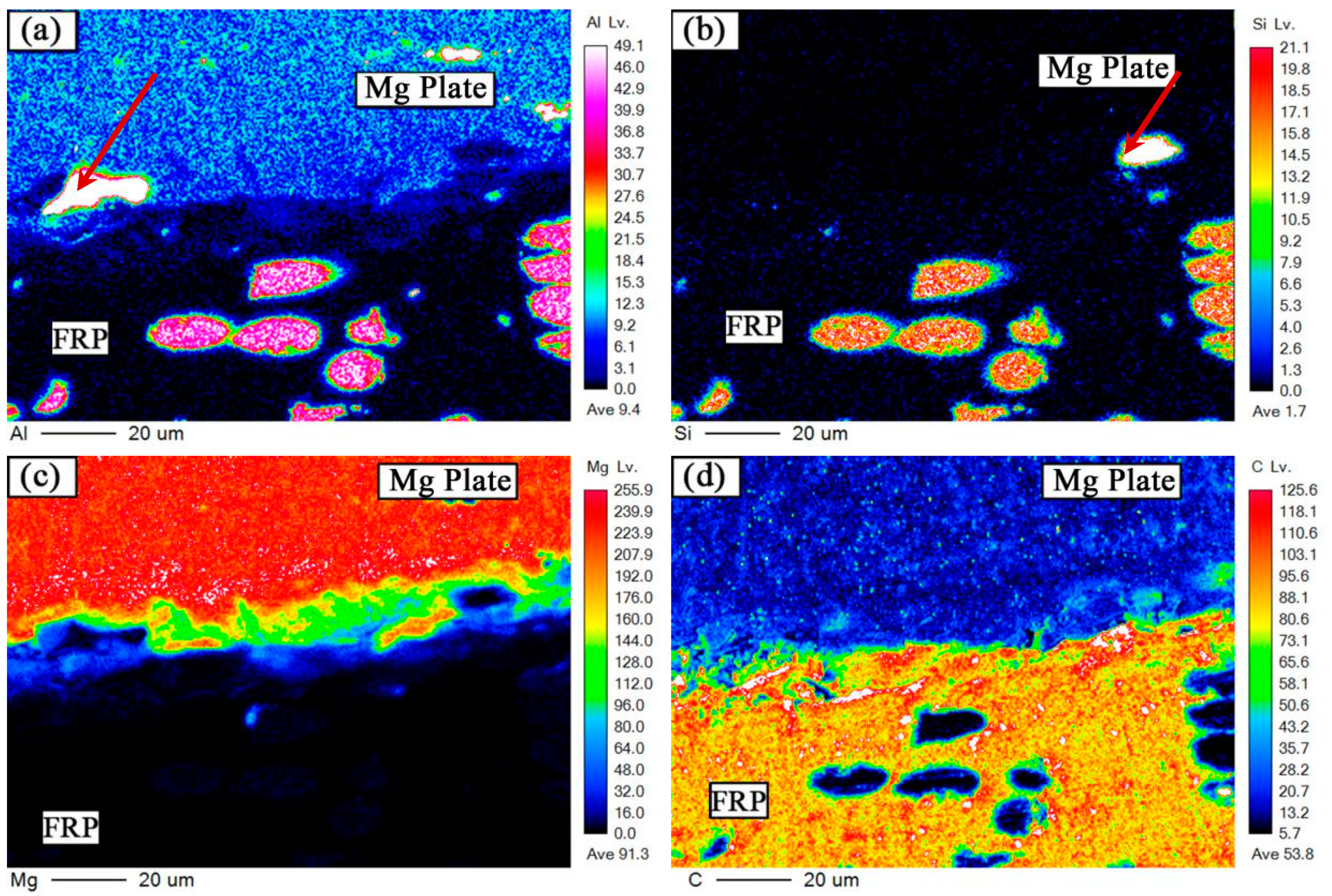
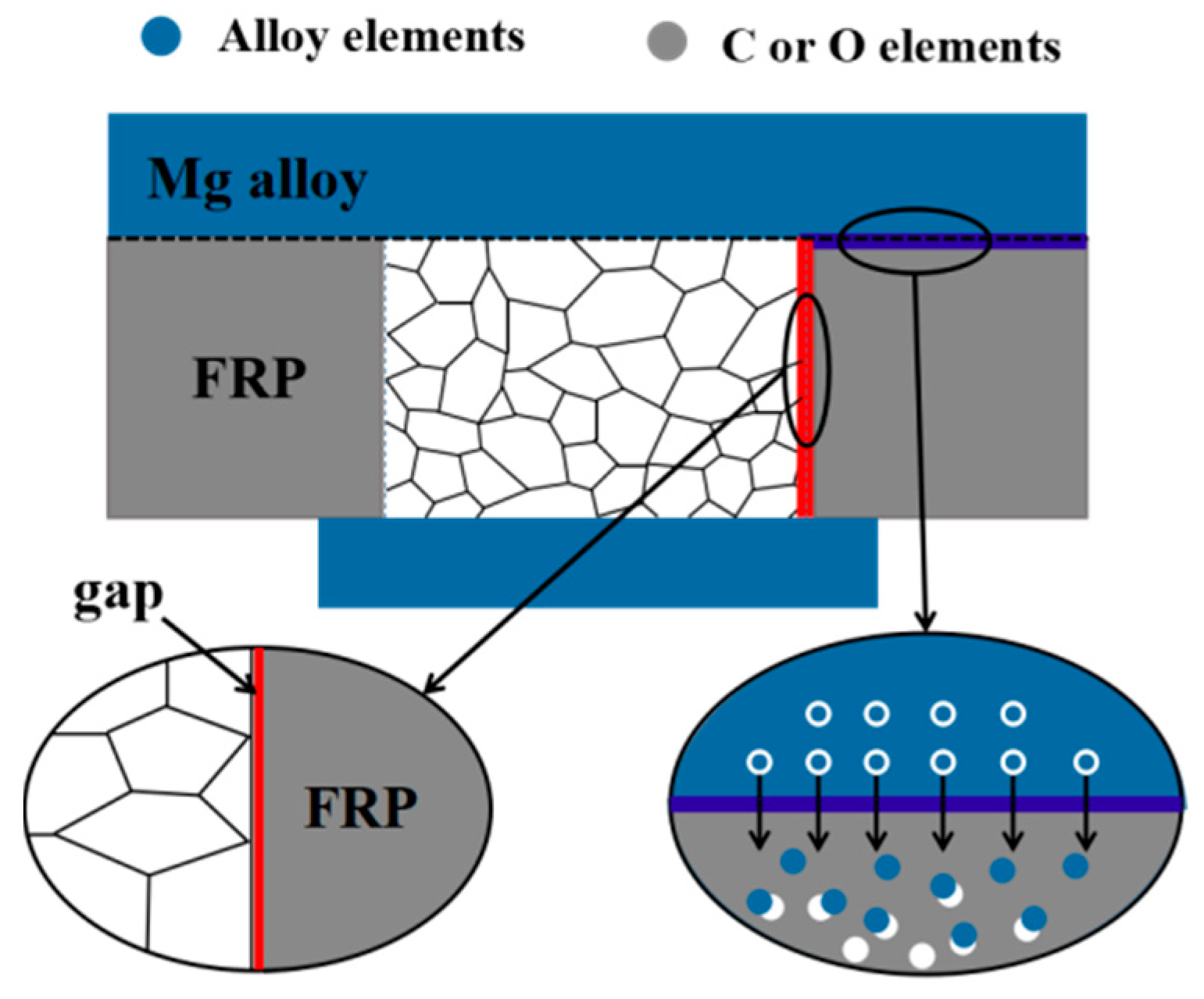
3.3. The Bonding Mechanism of Interface between the Mg and FRP
4. Conclusions
Author Contributions
Funding
Conflicts of Interest
References
- Goushegir, S.M.; Dos Santos, J.F.; Amancio-Filho, S.T. Friction Spot Joining of Aluminum AA2024/carbon-fiber Reinforced Poly(Phenylene Sulfide) Composite Single Lap Joints: Microstructure and Mechanical Performance. Mater. Des. 2014, 54, 196–206. [Google Scholar] [CrossRef]
- González Palencia, J.C.; Sakamaki, T.; Araki, M.; Shiga, S. Impact of Powertrain Electrification, Vehicle Size Reduction and Lightweight Materials Substitution on Energy Use, CO2 Emissions and Cost of a Passenger Light-Duty Vehicle Fleet. Energy 2015, 93, 1489–1504. [Google Scholar] [CrossRef]
- Sun, W.; Chen, X.; Wang, L. Analysis of Energy Saving and Emission Reduction of Vehicles Using Light Weight Materials. Energy Procedia 2016, 88, 889–893. [Google Scholar] [Green Version]
- Kojima, Y. Platform Science and Technology for Advanced Magnesium Alloys. Mater. Sci. Forum 2000, 350, 3–18. [Google Scholar] [CrossRef]
- Wang, H.; Liu, L.; Liu, F. The Characterization Investigation of Laser-Arc-Adhesive Hybrid Welding of Mg to Al Joint Using Ni Interlayer. Mater. Des. 2013, 50, 463–466. [Google Scholar] [CrossRef]
- Song, G.; Li, T.; Chen, L. Interface bonding mechanism of immiscible Mg/steel by butt fusion welding with filler wire. Mater. Sci. Eng. B 2018, 736, 306–315. [Google Scholar] [CrossRef]
- Tan, C.; Chen, B.; Meng, S.; Zhang, K.; Song, X.; Zhou, L.; Feng, J. Microstructure and Mechanical Properties of Laser Welded-Brazed Mg/Ti Joints with AZ91 Mg Based Filler. Mater. Des. 2016, 99, 127–134. [Google Scholar] [CrossRef]
- Liu, L.; Ren, D.; Liu, F. A Review of Dissimilar Welding Techniques for Magnesium Alloys to Aluminum Alloys. Materials 2014, 7, 3735–3757. [Google Scholar] [CrossRef] [Green Version]
- Zhou, L.; Li, G.H.; Zhang, R.X.; Zhou, W.L.; He, W.X.; Huang, Y.X.; Song, X.G. Microstructure evolution and mechanical properties of friction stir spot welded dissimilar aluminum-copper joint. J. Alloy. Compd. 2019, 775, 372–382. [Google Scholar] [CrossRef]
- Bian, H.; Song, X.; Hu, S.; Lei, Y.; Jiao, Y.; Duan, S.; Feng, J.; Long, W. Microstructure evolution and mechanical properties of titanium/alumina brazed joints for medical implants. Metals 2019, 9, 644. [Google Scholar] [CrossRef]
- Zhao, H.; Yu, M.; Jiang, Z.; Zhou, L.; Song, X. Interfacial microstructure and mechanical properties of Al/Ti dissimilar joints fabricated via friction stir welding. J. Alloy Compd. 2019, 789, 139–149. [Google Scholar] [CrossRef]
- Stokes, V.K. Joining Methods for Plastics and Plastic Composites: An Overview. Polym. Eng. Sci. 1989, 29, 1310–1324. [Google Scholar] [CrossRef]
- Nagatsuka, K.; Yoshida, S.; Tsuchiya, A.; Nakata, K. Direct Joining of Carbon-Fiber–Reinforced Plastic to an Aluminum Alloy Using Friction Lap Joining. Compos. Part B Eng. 2015, 73, 82–88. [Google Scholar] [CrossRef]
- Kumar, S.B.; Sridhar, I.; Sivashanker, S.; Osiyemi, S.O.; Bag, A. Tensile Failure of Adhesively Bonded CFRP Composite Scarf Joints. Mater. Sci. Eng. B 2006, 132, 113–120. [Google Scholar] [CrossRef]
- Kelly, G. Load Transfer in Hybrid (Bonded/Bolted) Composite Single-Lap Joints. Compos. Struct. 2005, 69, 35–43. [Google Scholar] [CrossRef]
- Kolesnikov, B.; Herbeck, L.; Fink, A. CFRP/titanium Hybrid Material for Improving Composite Bolted Joints. Compos. Struct. 2008, 83, 368–380. [Google Scholar] [CrossRef]
- Tan, X.; Zhang, J.; Shan, J.; Yang, S.; Ren, J. Characteristics and Formation Mechanism of Porosities in CFRP During Laser Joining of CFRP and Steel. Compos. Part B Eng. 2015, 70, 35–43. [Google Scholar] [CrossRef]
- Wahba, M.; Kawahito, Y.; Katayama, S. Laser Direct Joining of AZ91D Thixomolded Mg Alloy and Amorphous Polyethylene Terephthalate. J. Mater. Process. Technol. 2011, 211, 1166–1174. [Google Scholar] [CrossRef]
- Jung, K.W.; Kawahito, Y.; Takahashi, M.; Katayama, S. Laser Direct Joining of Carbon Fiber Reinforced Plastic to Zinc-Coated Steel. Mater. Des. 2013, 47, 179–188. [Google Scholar] [CrossRef]
- Meschut, G.; Janzen, V.; Olfermann, T. Innovative and Highly Productive Joining Technologies for Multi-Material Lightweight Car Body Structures. J. Mater. Eng. Perform. 2014, 23, 1515–1523. [Google Scholar] [CrossRef]
- Ling, Z.; Li, Y.; Luo, Z.; Feng, Y.; Wang, Z. Resistance Element Welding of 6061 Aluminum Alloy to Uncoated 22MnMoB Boron Steel. Mater. Manuf. Process. 2016, 31, 2174–2180. [Google Scholar] [CrossRef]
- Li, Y.B.; Wei, Z.Y.; Wang, Z.Z.; Li, Y.T. Friction Self-Piercing Riveting of Aluminum Alloy AA6061-T6 to Magnesium Alloy AZ31B. J. Manuf. Sci. Eng. 2013, 135, 061007. [Google Scholar] [CrossRef]
- Zhang, Z.; Fan, F.; Wang, J.; Liu, L. Effects of Oxide on Plasma in Arc Welding with Activating Fluxes. IEEE T Plasma Sci. 2015, 43, 465–471. [Google Scholar] [CrossRef]
- Goushegir, S.M.; Dos Santos, J.F.; Amancio-Filho, S.T. Influence of Process Parameters on Mechanical Performance and Bonding Area of AA2024/carbon-fiber-reinforced Poly(Phenylene Sulfide) Friction Spot Single Lap Joints. Mater. Des. 2015, 83, 431–442. [Google Scholar] [CrossRef]
- Meschut, G.; Hahn, O.; Janzen, V.; Olfermann, T. Innovative Joining Technologies for Multi-Material Structures. Weld. World 2014, 58, 65–75. [Google Scholar] [CrossRef]
- Blaga, L.; Dos Santos, J.F.; Bancila, R.; Amancio-Filho, S.T. Friction Riveting (FricRiveting) as a New Joining Technique in GFRP Lightweight Bridge Construction. Constr. Build. Mater. 2015, 80, 167–179. [Google Scholar] [CrossRef]
- Wang, H.; Yang, K.; Liu, L. The Analysis of Welding and Riveting Hybrid Bonding Joint of Aluminum Alloy and Polyether-Ether-Ketone Composites. J. Manuf. Process. 2018, 36, 301–308. [Google Scholar] [CrossRef]


| Element | Al | Si | Ca | Zn | Mn | Cu | Mg |
|---|---|---|---|---|---|---|---|
| Quantity | 3.2 | 0.07 | 0.04 | 1.2 | 0.8 | 0.01 | extra |
| Welding Parameters | Value |
|---|---|
| Welding speed (rad/min) | 36 |
| Arc welding current (A) | 70 |
| Laser power (W) | 215 |
| Defocus distance (mm) | 0 |
| Area | The Rivet I Joint | The Rivet II Joint |
|---|---|---|
| Fusion zone | 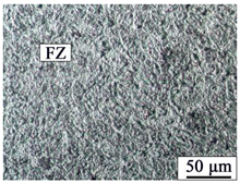 | 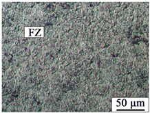 |
| HAZ on Mg plate | 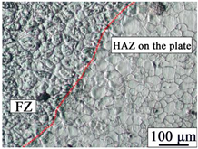 |  |
| HAZ on rivet |  | 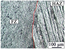 |
© 2019 by the authors. Licensee MDPI, Basel, Switzerland. This article is an open access article distributed under the terms and conditions of the Creative Commons Attribution (CC BY) license (http://creativecommons.org/licenses/by/4.0/).
Share and Cite
Wang, H.; Li, N.; Liu, L. Investigation of the Joining Technology of FRP/AZ31B Magnesium Alloy by Welding and Riveting Hybrid Bonding Method. Materials 2019, 12, 2167. https://doi.org/10.3390/ma12132167
Wang H, Li N, Liu L. Investigation of the Joining Technology of FRP/AZ31B Magnesium Alloy by Welding and Riveting Hybrid Bonding Method. Materials. 2019; 12(13):2167. https://doi.org/10.3390/ma12132167
Chicago/Turabian StyleWang, Hongyang, Nan Li, and Liming Liu. 2019. "Investigation of the Joining Technology of FRP/AZ31B Magnesium Alloy by Welding and Riveting Hybrid Bonding Method" Materials 12, no. 13: 2167. https://doi.org/10.3390/ma12132167