Line heating is a typical process in the plate forming of ships. In the past, the operation was mostly manual and included the use of a flame heater. With advancements in research and the development of automated line heating equipment, flame heating by oxyacetylene combustion has shown its limitations because of the difficulty with temperature control. Induction heating is used extensively for the forming of plates because it is easily controlled and has high efficiency.
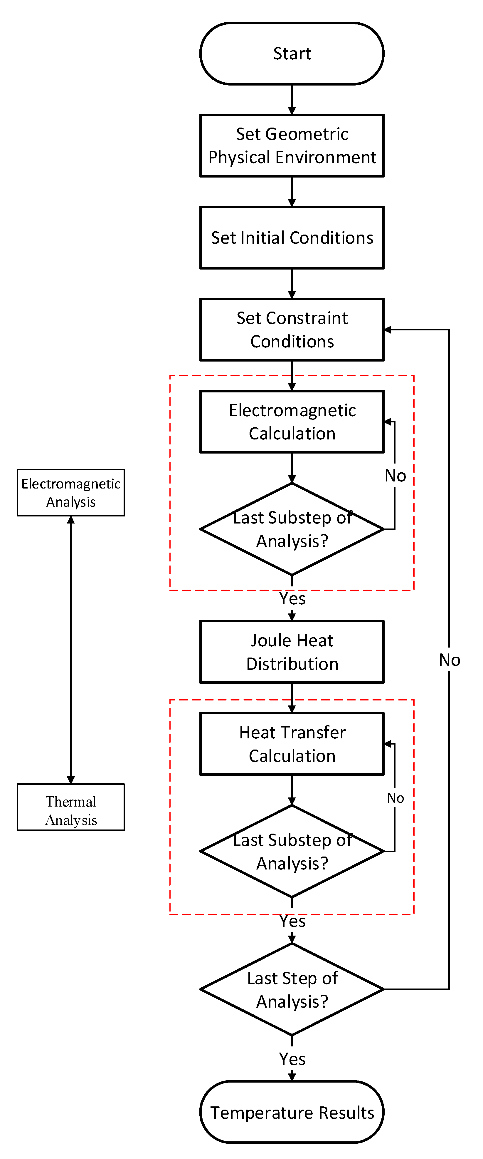
In the computation process mentioned above, it is necessary to calculate the electromagnetic field and the temperature field. The Joule heat obtained from the electromagnetic calculation is the input of the heat transfer calculation. It is necessary to frequently re-divide the grid based on the coil position when performing moving induction heating forming simulations, which increase the time of computations and decrease computation efficiency.
Some studies have investigated methods to improve computation efficiency. Monzel [
1] used the neural network method to carry out preliminary research on the features of the inductive current distribution during transverse flux induction heating. He gave measures for reducing cable loss by changing each coil’s current to change the heat source distribution. The typical form of heat source density was given in the study, but the corresponding simplified numerical method was not mentioned. Bay [
2] postulated that the temperature calculation relative to the electromagnetic calculation was a quasi-static process and proposed mathematical and numerical models for the coupled axisymmetric induction heating process. The model simplified the full-coupling process into a weak coupling process, used the eddy current obtained in the electromagnetic calculation as the heat generation rate in the temperature calculation, and presented a preliminary calculation method for the heat generation rate, but the expression for the heat source model was not given. Luo [
3,
4,
5,
6] carried out finite element calculations on the temperature field and the deformation field during high-frequency induction heating. He compared the relevant results with the experimental results, which avoided the electromagnetic coupling calculation. He gave the corresponding heat source model, but the calculation method for the heat source model and the corresponding relationship of various parameters in the model with the actual coil were not discussed. Liu [
7] presented a numerical method for the temperature field of induction heating and studied the law of temperature distribution. When handling the electromagnetic-thermal coupling problem, a heat source model based on an empirical formula was used, but the calculation process for the model was not given. Hu [
8] proposed the use of an equivalent heat source to replace the electromagnetic coupling calculation in induction heating and carried out experimental verification of the proposed heat source model, but did not give an explicit expression for the heat source model. Zhang [
9] analyzed the similarities and differences of induction heating and flame heating in the line heating of ship plates and thought that induction heating was feasible in heat forming. When handling the induction heating process, he provided a heat source model for induction heating and used it as the initial input for the thermal distribution calculation. Compared with the experimental results, the errors of the calculation results satisfied practical engineering requirements. However, the model was simplified and the meaning of various model parameters and the corresponding numerical methods were not explained. Bae [
10] proposed a two-dimensional circular heat input model to simulate the induction heating process and obtained satisfactory results, but the expression of the heat source model was not taken into account. Jeong [
11] simplified coupled induction heating into the electromagnetic calculations and thermal calculations. He used statistical methods to describe the correlation between deformation and the input parameters, but the expression of the heat source model was not described in the study. Bai [
12] used stepwise analysis to carry out coupling analysis within a typical time to obtain the state of induction heat distribution. He used the distribution as the moving heat source for a subsequent calculation, but the expression for the heat source was not given. Kubota [
13] used a three-dimensional coupling and heat source model to perform calculations on the induction heating process and found that the results were consistent with measured results. The heat source model was obtained based on the obtained temperature field. Yang [
14] proposed a heat source model based on the characteristics of the induction heating eddy current and used the finite element method (FEM) and relevant tests to verify the effectiveness of the model. The proposed heat source model was based on empirical methods and only targeted a particular coil form without giving the expression form of the corresponding heat source for other coil forms. Through theoretical analysis, Li [
15] studied the analytical solution for obtaining the heat generation rate in the semi-infinite space during induction heating and discussed the effects of relevant parameters on the heat generation rate. To compare the difference in residual stress in a plate after single heating and double heating, Aung [
16] proposed numerical methods based on a surface heat source and a body heat source. The effectiveness of the heat source models was verified through the experiment. Aung provided the expression form for the heat source model but did not discuss its calculation. Riccio [
17] used different numerical models to study the bonding of carbon fiber reinforced polymer components with induction heating. ABAQUS was used to carry out electromagnetic analysis to obtain the energy loss caused by the Joule effect. He provided the finite element calculation model but not the expression for the Joule heat of the coil. In other studies related to the induction heating process and induction coil design [
18,
19,
20], the full-coupling numerical method was also used for the induction heating calculations. Although the results were satisfactory, the time cost was high and the applicability was low for coils of different shapes and sizes or with different processing conditions. Zhang [
21] replaced the electromagnetic-thermal coupling calculations with a heat source model corresponding to a discrete form and proposed a simplified calculation method for the high-frequency induction heat source. The computation efficiency for the calculation of a certain specific induction heating parameter was greatly improved, but any change in the induction heating parameters necessitated repeating the entire calculation.
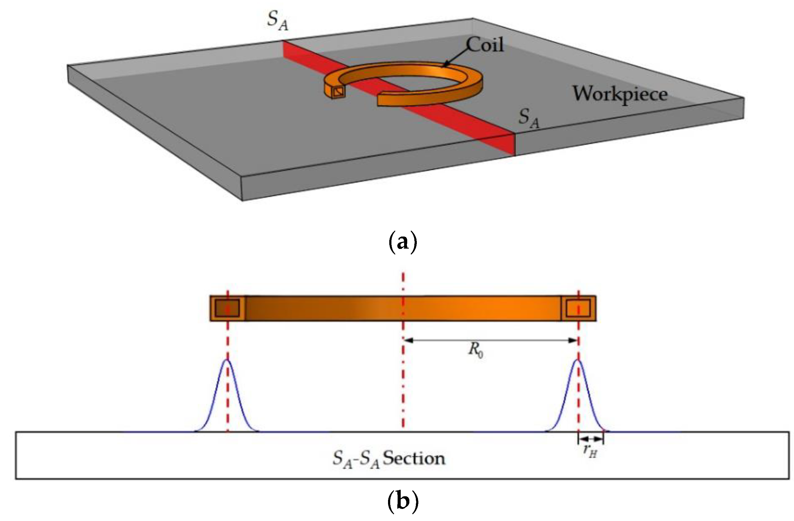
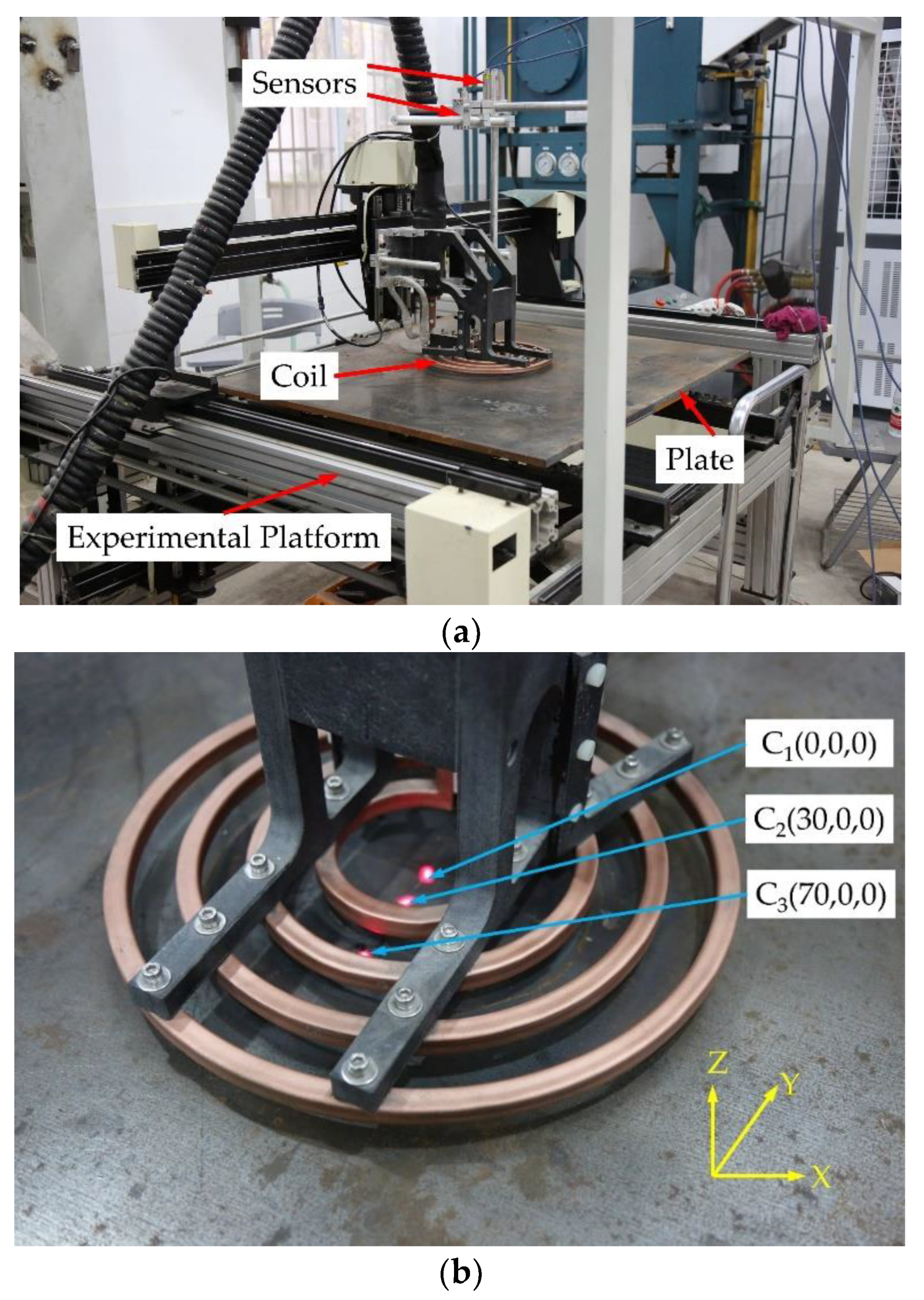
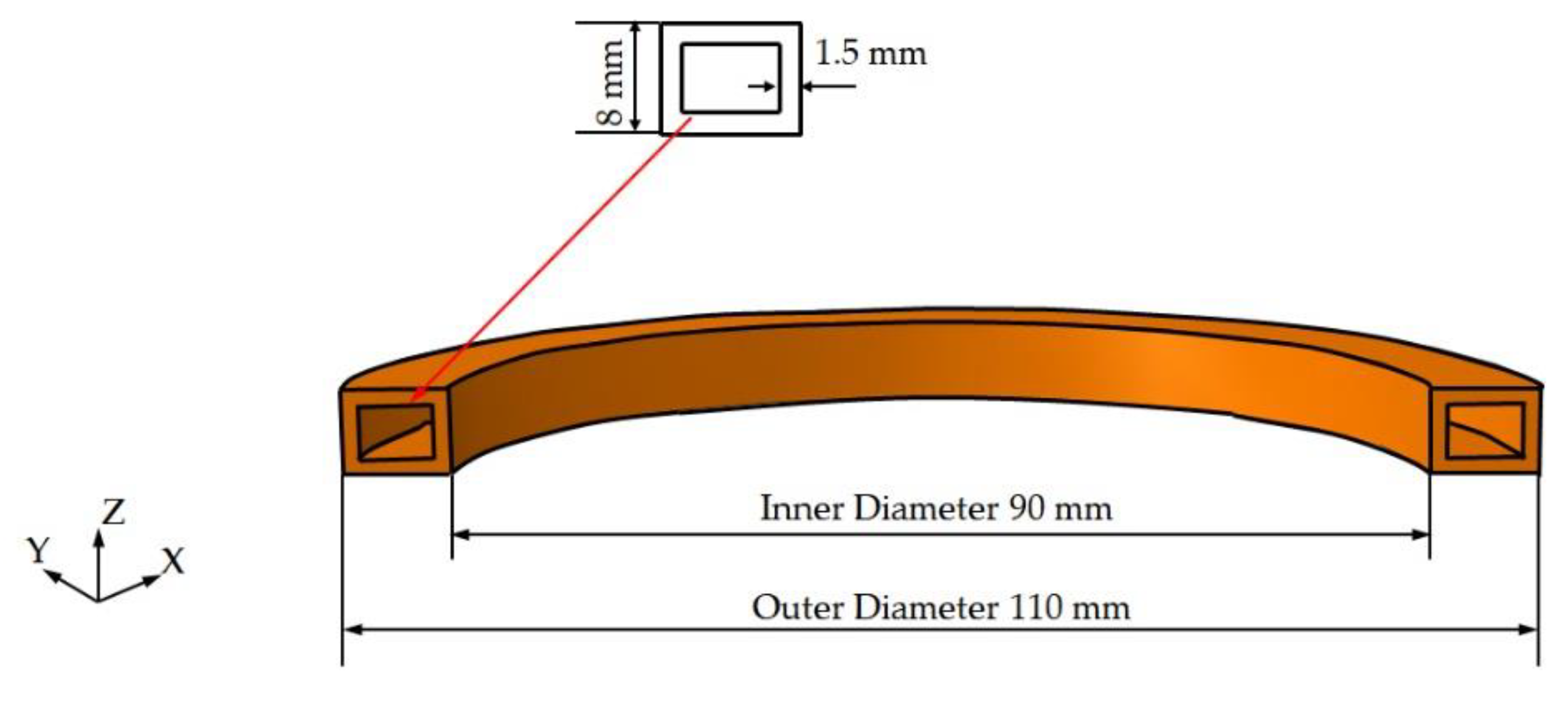
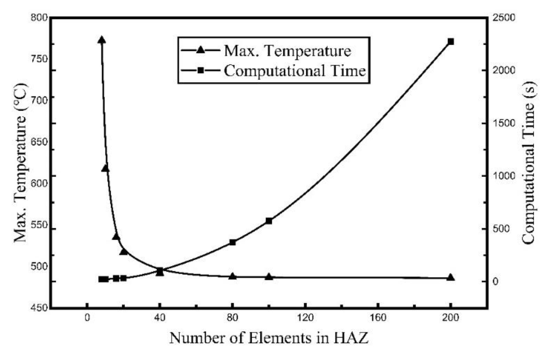
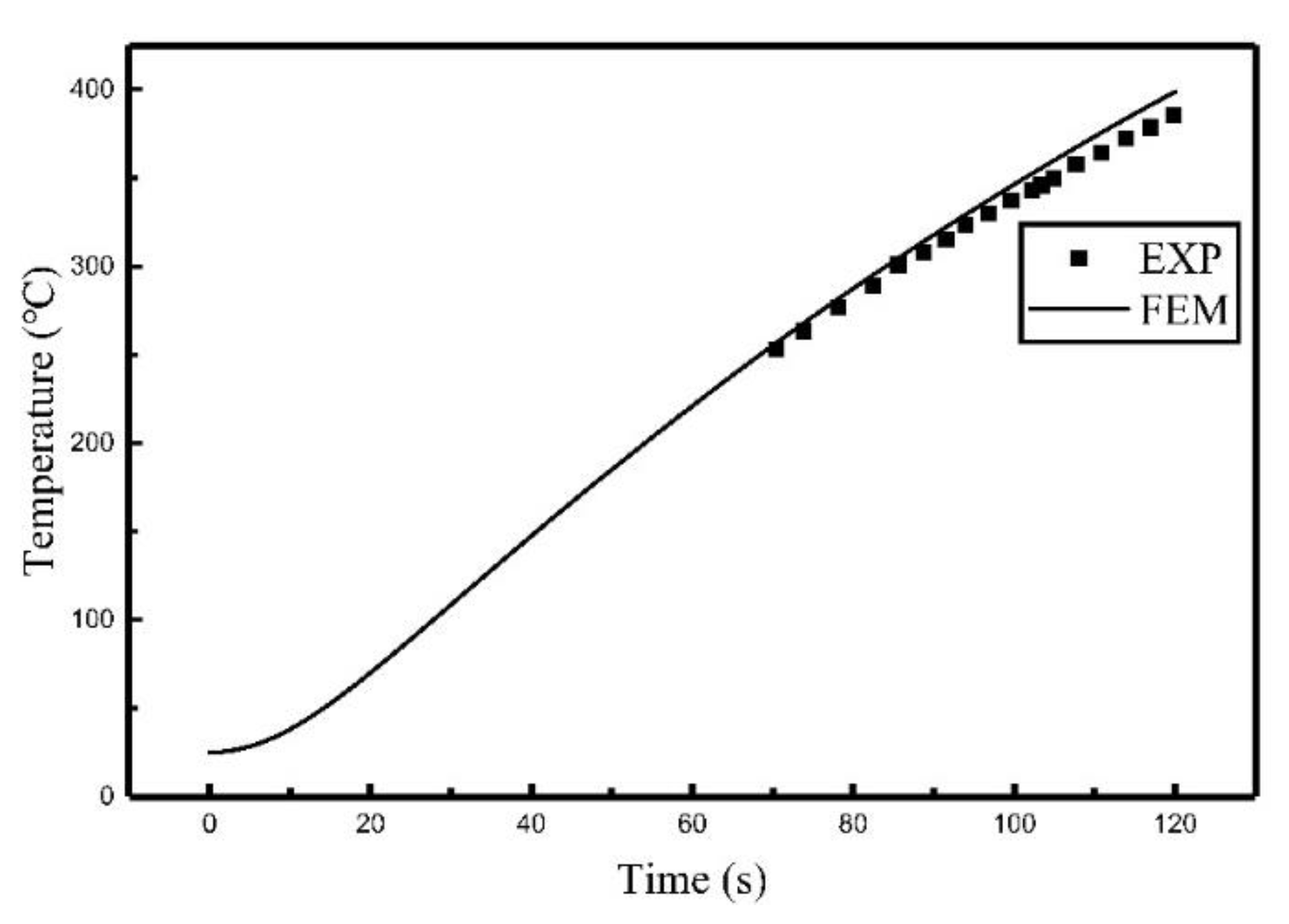
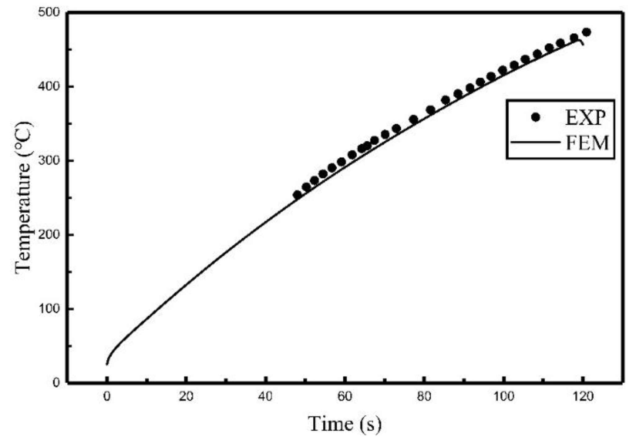
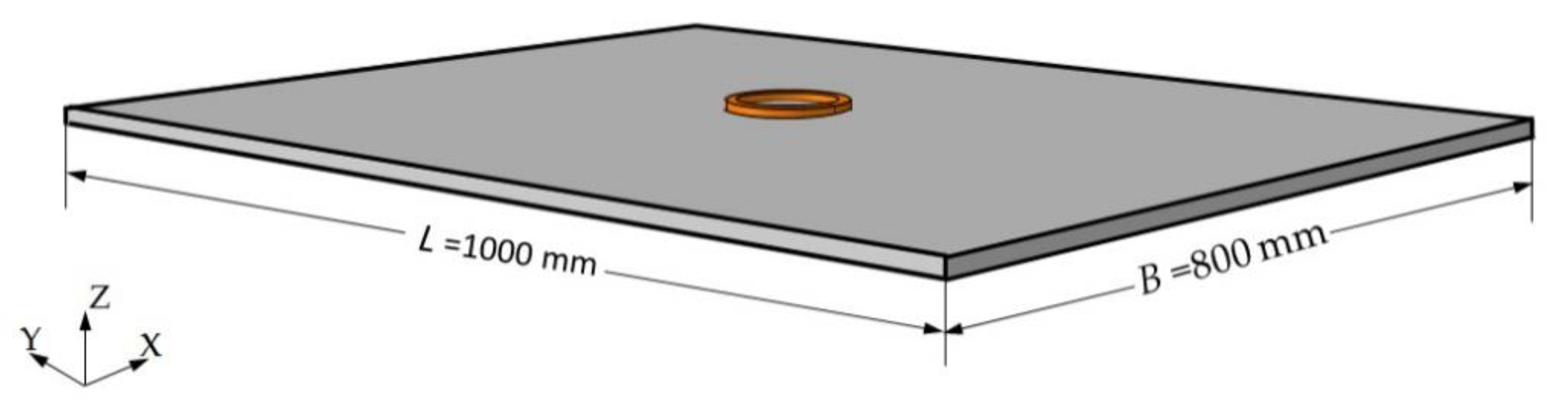
The induction heating calculation, especially the direct calculation of the moving induction heating process, results in a long computation time due to the need to continuously change the grid. However, the use of the heat flux to replace the coil can achieve high precision and reduce the computation time. Currently, most studies focus on empirical methods, and there are comparatively few studies that calculate the heat source and investigate the effect of the coil on the model. Based on these, the analytical method was employed in this study to calculate the heat source model for the induction coil. The effects of coil shapes on the heat source were examined. In addition, related experiments were conducted to verify the obtained heat source model for single-coil and multi-coil.


