The Significant Impact of Carbon Nanotubes on the Electrochemical Reactivity of Mg-Bearing Metallic Glasses with High Compressive Strength

Abstract
:1. Introduction
2. Experimental Procedure
2.1. Materials
2.2. Preparation Process of Metallic Glass
- (1)
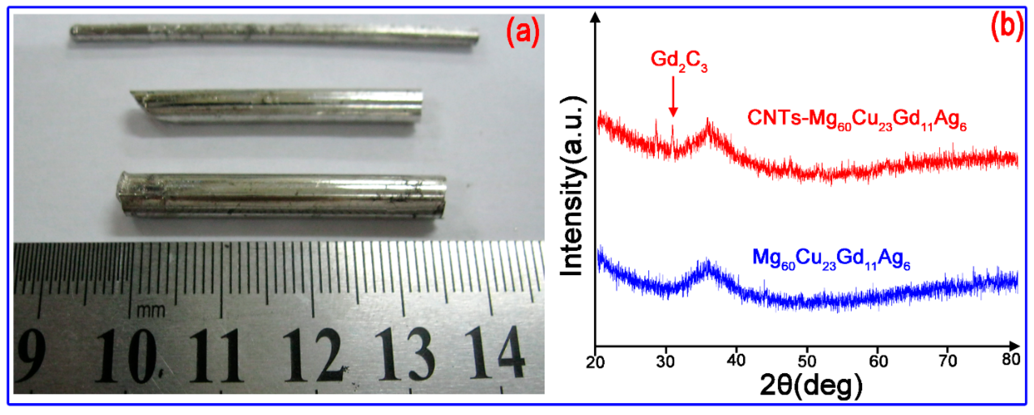
- Cu-Gd-Ag intermediate alloy was prepared by arc-melting under a Ti-gettered argon atmosphere in a water-cooled copper container, as shown in Figure 2a. The button-like alloy ingot was obtained after melting the intermediate alloy while using vacuum arc melting. Each ingot was re-melted four times to ensure a homogeneous composition.
- (2)
- Next, Mg was mixed with the intermediate, Cu-Gd-Ag alloy, based on the atomic ratio of the final alloy. The crystalline Mg-Cu-Gd-Ag master alloy was obtained by induction melting in an electromagnetic induction furnace. Figure 2b shows the internal view of electromagnetic induction melting furnace.
- (3)
- In the third stage, the master alloy was ball milled (Figure 2c) to obtain small particles, and then mixed with the desired content of CNTs. The ball milling was carried out for 2–6 hours, and pressed as a pellet.
- (4)
- The mixed pellet was placed in a high-temperature-resistance stainless steel crucible, which was melted by electromagnetic induction, and the liquid metal was rapidly pressed in a water-cooled copper mold while using a hydraulic ejector rod. The liquid metal was rapidly condensed into metallic glass. Figure 2d shows the water cooling die casting system with copper mold.
2.3. Methods for Testing the Properties of Experimental Materials
3. Results
3.1. Amorphous Structure
3.2. Effect of CNTs on Mechanical Properties of Mg Alloy Glass
3.3. Corrosion Resistance
4. Discussion
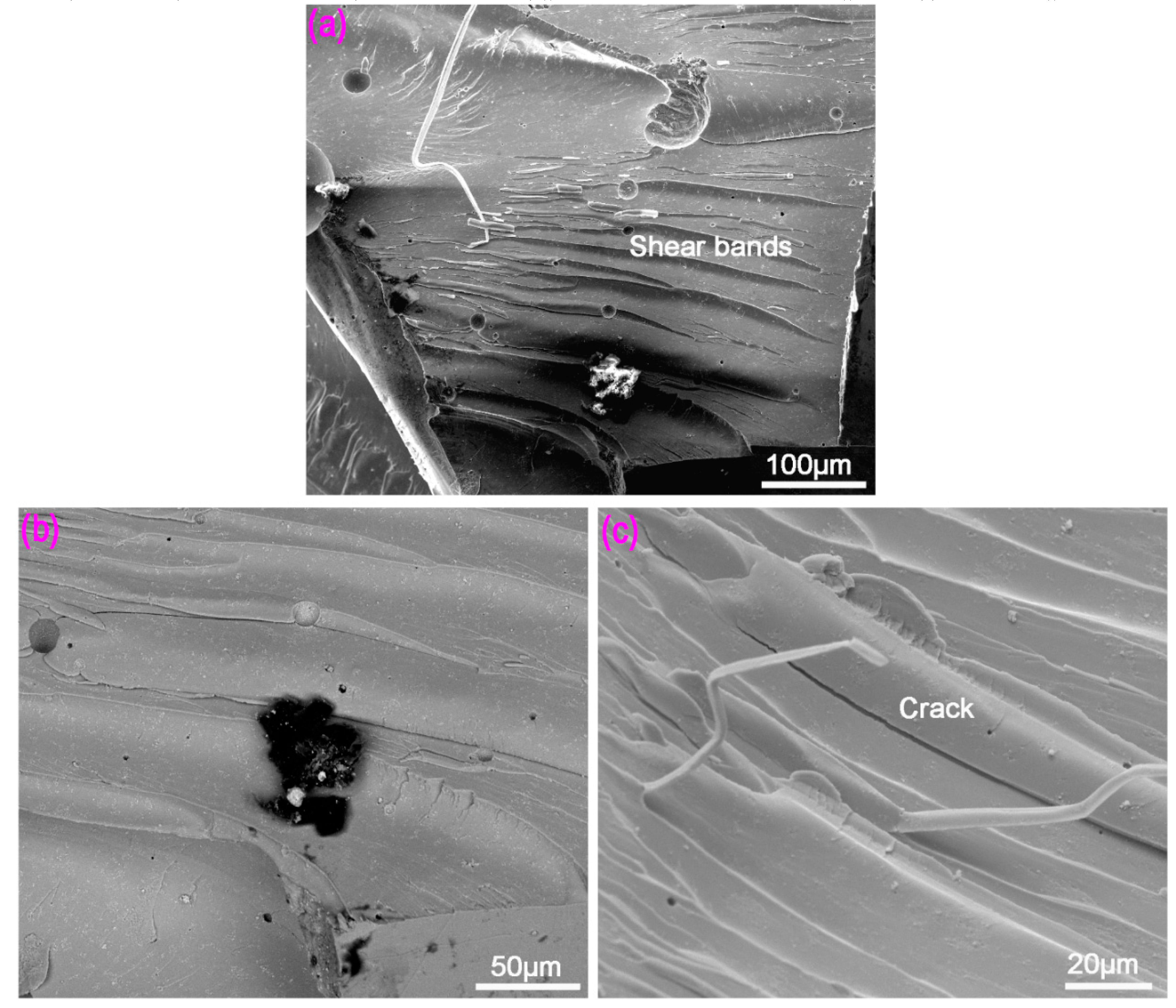
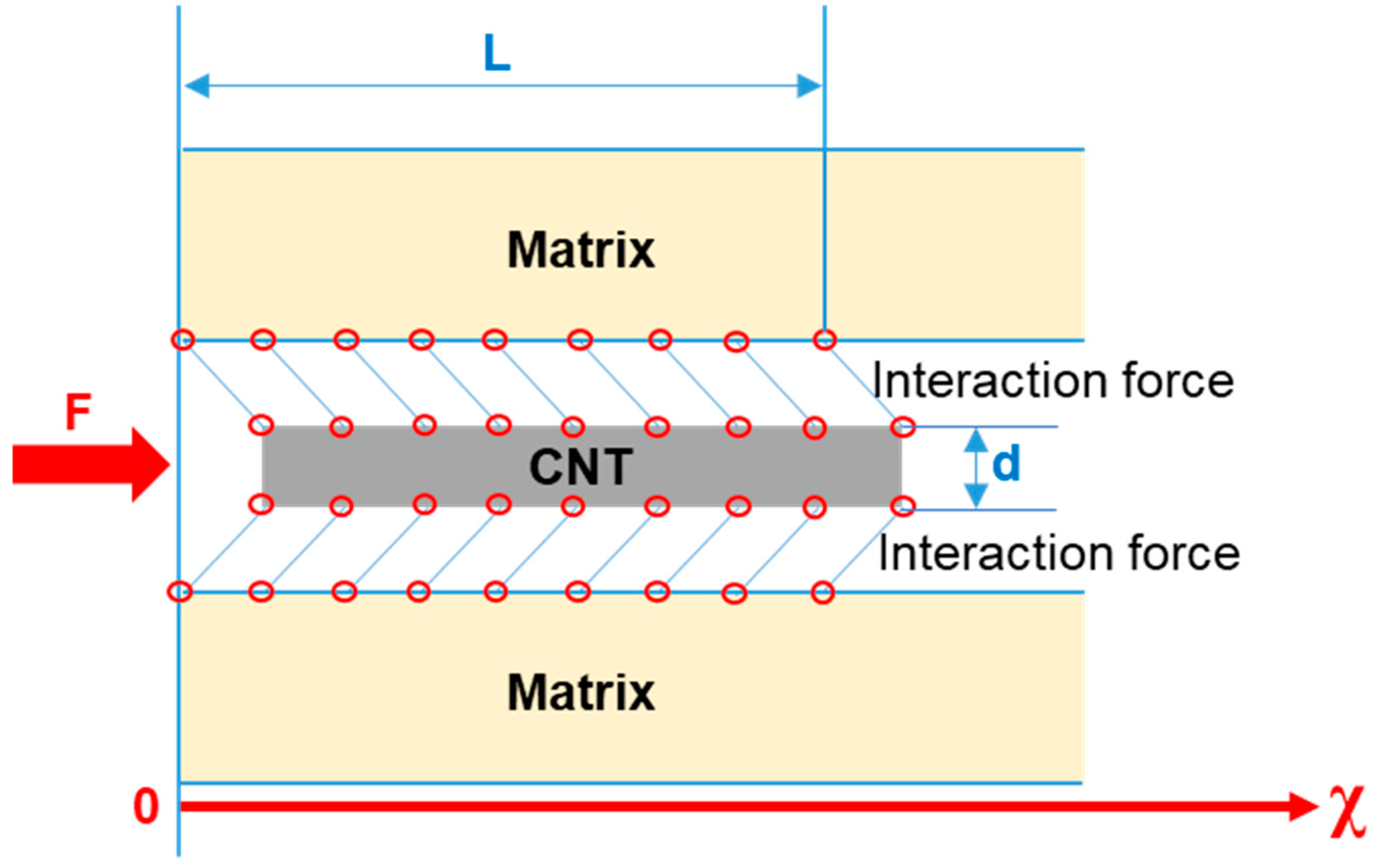
4.1. Shear Deformation Resistance Mechanism of CNTs
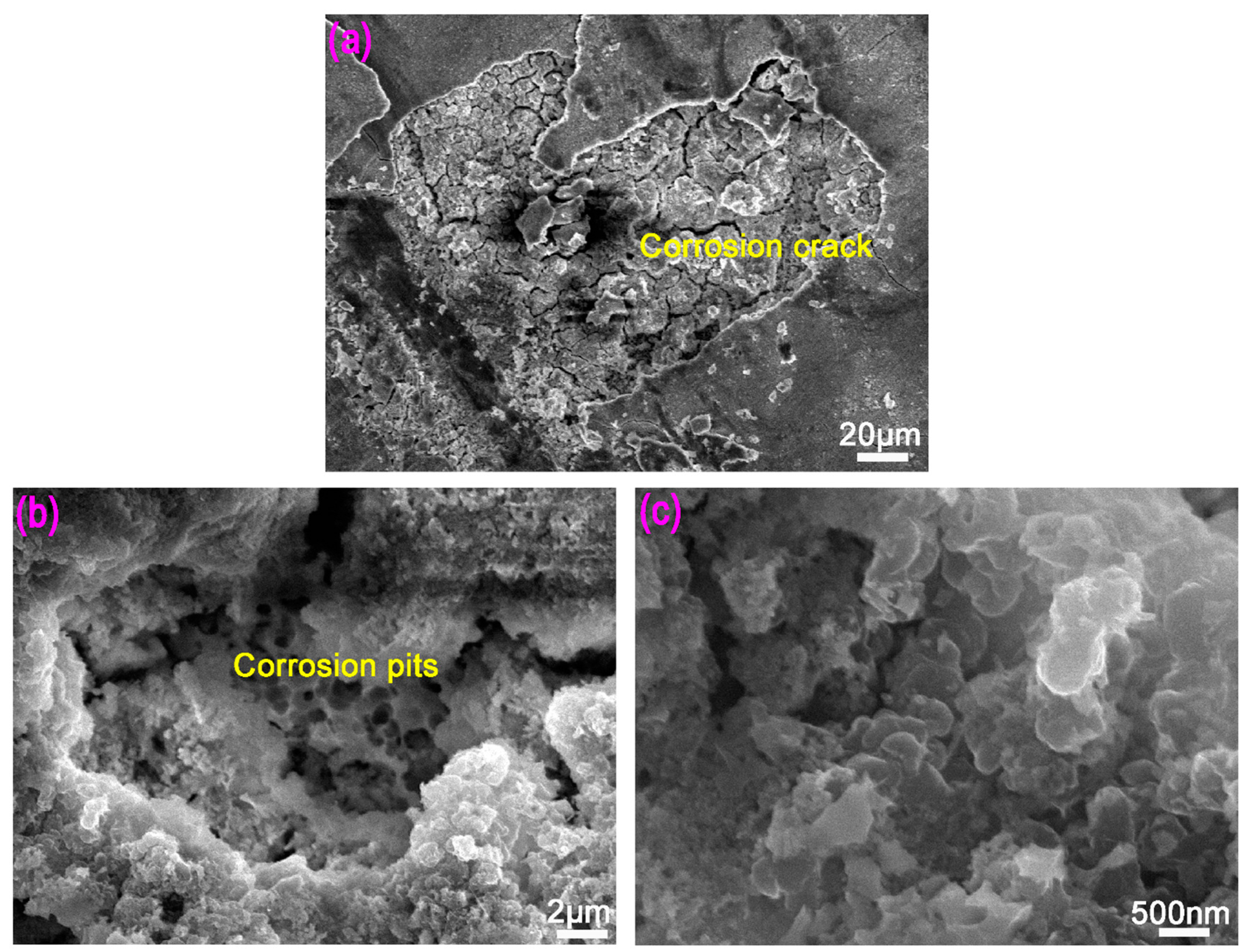
4.2. The Effect of CNTs in Improving the Corrosion Performance of Mg-BMGs
5. Conclusions
- (1)
- On adding 3 vol % CNTs, the compressive strength was raised by 812 MPa of Mg-BMG to 1007 MPa of CNTs-Mg-BMG, and increase of ~24%.
- (2)
- The corrosion resistance of amorphous matrix in 0.1 mol/L NaOH solution was improved by the addition of CNTs, where the corrosion rate decreased from 0.96 mg/cm2·d of Mg-BMG to 0.66 mg/cm2·d of CNTs-Mg-BMG, and a decrease of ~30%.
- (3)
- Under the action of compressive stress, the damage of the binding force between the CNTs and the metal matrix can absorb the stress deformation energy, such that the compressive stress is shared and the compressive strength enhanced.
- (4)
- CNT improved the corrosion performance because of its high corrosion resistance and poor wettability, and it included the bridging effect between corrosive oxide film and the matrix, which made the oxide film difficult to peel-off, thereby improving the corrosion resistance.
Author Contributions
Funding
Acknowledgments
Conflicts of Interest
References
- Inoue, A.; Ohtera, K.; Kita, K.; Masumoto, T. New Amorphous Mg-Ce-Ni Alloys with High Strength and Good Ductility. Jpn. J. Appl. Phys. Pt Lett. 1988, 27, L2248–L2251. [Google Scholar] [CrossRef]
- Zhi, W. High strength Al-Gd-Ni-Co alloys from amorphous precursors. Ph.D. Thesis, Technische Universität Dresden, Tatzberg, Germany, 2014. [Google Scholar]
- Shanthi, M.; Gupta, M.; Jarfors, A.E.W.; Tan, M.J. Producing Magnesium Metallic Glass By Disintegrated Melt Deposition. AIP Conf. Proc. 2011, 1315, 781. [Google Scholar]
- Laws, K.J.; Granata, D.; Löffler, J.F. Alloy design strategies for sustained ductility in Mg-based amorphous alloys–Tackling structural relaxation. Acta Mater. 2016, 103, 735–745. [Google Scholar] [CrossRef]
- Inoue, A.; Masumoto, T. Mg-based amorphous alloys. Mater. Sci. Eng. A 1993, 173, 1–8. [Google Scholar] [CrossRef]
- Gu, X.; Shiflet, G.J.; Guo, F.Q.; Poon, S.J. Mg-Ca-Zn bulk metallic glasses with high strength and significant ductility. J. Mater. Res. 2005, 20, 1935–1938. [Google Scholar] [CrossRef]
- Qiang, Z.; Jian, X.; Ma, E. High glass-forming ability correlated with fragility of Mg-Cu(Ag)-Gd alloys. J. Appl. Phys. 2007, 102, 1924. [Google Scholar]
- Xi, X.K.; Zhao, D.Q.; Pan, M.X.; Wang, W.H.; Wu, Y.; Lewandowski, J.J. Fracture of brittle metallic glasses: Brittleness or plasticity. Phys. Rev. Lett. 2005, 94, 125510. [Google Scholar] [CrossRef]
- Zeng, R.; Dietzel, W.; Witte, F.; Hort, N.; Blawert, C. Progress and Challenge for Magnesium Alloys as Biomaterials. Adv. Eng. Mater. 2010, 10, B3–B14. [Google Scholar] [CrossRef]
- Jian, S.R.; Li, J.B.; Chen, K.W.; Jang, S.C.; Juang, J.Y.; Wei, P.J.; Lin, J.F. Mechanical responses of Mg-based bulk metallic glasses. Intermetallics 2010, 18, 1930–1935. [Google Scholar] [CrossRef]
- Gebert, A.; Wolff, U.; John, A.; Eckert, J.; Schultz, L. Stability of the bulk glass-forming Mg 65Y 10Cu 25 alloy in aqueous electrolytes. Mater. Sci. Eng. A 2001, 299, 125–135. [Google Scholar] [CrossRef]
- Gebert, A.; Rao, R.V.S.; Wolff, U.; Baunack, S.; Eckert, J.; Schultz, L. Corrosion behaviour of the Mg 65Y 10Cu 15Ag 10bulk metallic glass. Mater. Sci. Eng. A 2004, 375–377, 280–284. [Google Scholar] [CrossRef]
- Yao, H.B.; Li, Y.; Wee, A.T.S. Corrosion behavior of melt-spun Mg 65Ni 20Nd 15 and Mg 65Cu 25Y 10 metallic glasses. Electrochim. Acta 2003, 48, 2641–2650. [Google Scholar] [CrossRef]
- Sarkar, S.; Sardar, S.; Makhal, A.; Dutta, J.; Pal, S.K. Engineering FRET-Based Solar Cells: Manipulation of Energy and Electron Transfer Processes in a Light Harvesting Assembly. Springer 2014, 190, 267. [Google Scholar]
- Zhang, R.; Zhang, Y.; Wei, F. Horizontally aligned carbon nanotube arrays: Growth mechanism, controlled synthesis, characterization, properties and applications. Chem. Soc. Rev. 2017, 46, 3661–3715. [Google Scholar] [CrossRef] [PubMed]
- Zhang, R.F.; Wen, Q.; Qian, W.Z.; Su, D.S.; Zhang, Q.; Wei, F. Superstrong ultralong carbon nanotubes for mechanical energy storage. Adv. Mater. 2011, 23, 3387–3391. [Google Scholar] [CrossRef] [PubMed]
- Zhao, Q.; Nardelli, M.B.; Bernholc, J. Ultimate strength of carbon nanotubes: A theoretical study. Phys. Rev. B 2002, 65, 1441–1445. [Google Scholar] [CrossRef]
- Carneiro, O.S.; Covas, J.A.; Bernardo, C.A.; Caldeira, G.; Van Hattum, F.W.J.; Ting, J.M.; Alig, R.L.; Lake, M.L. Production and assessment of polycarbonate composites reinforced with vapour-grown carbon fibres. Compos. Sci. Technol. 1998, 58, 401–407. [Google Scholar] [CrossRef]
- Thostenson, E.T.; Li, W.Z.; Wang, D.Z.; Ren, Z.F.; Chou, T.W. Carbon nanotube/carbon fiber hybrid multiscale composites. J. Appl. Phys. 2002, 91, 6034–6037. [Google Scholar] [CrossRef]
- Thostenson, E.T.; Ren, Z.; Chou, T.W. Advances in the science and technology of carbon nanotubes and their composites: A review. Compos. Sci. Technol. 2001, 61, 1899–1912. [Google Scholar] [CrossRef]
- Bian, Z.; Wang, R.J.; Wang, W.H.; Zhang, T.; Inoue, A. Carbon-Nanotube-Reinforced Zr-Based Bulk Metallic Glass Composites and Their Properties. Adv. Funct. Mater. 2010, 14, 55–63. [Google Scholar] [CrossRef]
- Peng, H.; Li, S.S.; Qi, Y.P.; Huang, T.Y. Mg-Ni-Gd-Ag bulk metallic glass with improved glass-forming ability and mechanical properties. Intermetallics 2011, 19, 829–832. [Google Scholar] [CrossRef]
- Peng, H.; Li, S.S.; Huang, T.Y. Improvement of corrosion resistance in NaOH solution and glass forming ability of as-cast Mg-based bulk metallic glasses by microalloying. China Foundry 2011, 8, 5–8. [Google Scholar]
- Zhao, P.; Li, S.S.; Gao, G.H.; Bai, B.Z.; Misra, R.D.K. Mechanical Behavior of Carbon Nanotube-Reinforced Mg-Cu-Gd-Ag Bulk Metallic Glasses. Mater. Sci. Eng. A 2015, 641, 116–122. [Google Scholar] [CrossRef]
- Bai, Z.; Li, M.; Jing, Z.; Cao, S.; Ying, W.; Liao, C.; Misra, R.D.K. Influence of side-polished fiber surface topography on surface plasmon resonance wavelengths and the full width at half maximum. IEEE Photon. J. 2017, 9, 1–8. [Google Scholar] [CrossRef]
- Zhang, K.K.; Ma, N.; Zhang, Z.L.; Yue, Y.; Sun, J.; Wu, Z.W.; Yang, Y.L. Electro-Superplastic Compression Behavior of 1.6%C Ultrahigh Carbon Steel and Its Electro-Superplastic Welding to 40Cr Steel. Trans. Mater. Heat Treat. 2010, 31, 28–32. [Google Scholar]
- Yadav, K.L.; Patel, P.K. Bimodal distribution of grains. Mater. Today 2016, 19, 56–67. [Google Scholar] [CrossRef]
- Li, J.F.; Zheng, Z.Q.; Ren, W.D.; Chen, W.J.; Zhao, X.S.; Li, S.C. Simulation on function mechanism of T1(Al 2CuLi) precipitate in localized corrosion of Al-Cu-Li alloys. Trans. Nonferrous Met. Soc. China 2006, 16, 1268–1273. [Google Scholar] [CrossRef]
- Randolph, L.D.; Palin, W.M.; Watts, D.C.; Genet, M.; Devaux, J.; Leloup, G.; Leprince, J.G. The effect of ultra-fast photopolymerisation of experimental composites on shrinkage stress, network formation and pulpal temperature rise. Dent. Mater. 2014, 30, 1280–1289. [Google Scholar] [CrossRef] [PubMed]
- Mei, J.N.; Soubeyroux, J.L.; Blandin, J.J.; Li, J.S.; Kou, H.C.; Fu, H.Z.; Zhou, L. Nanocrystallization-induced large room-temperature compressive plastic strain of Ti40Zr25Ni8Cu9Be18 BMG. J. Alloy Compd. 2011, 509, 1626–1639. [Google Scholar] [CrossRef]
- Eckert, J.; Das, J.; Pauly, S.; Duhamel, C. Mechanical properties of bulk metallic glasses and composites. Mrs Bulletin 2007, 32, 635–638. [Google Scholar] [CrossRef]
- Wang, G.; Zhao, D.Q.; Bai, H.Y.; Pan, M.X.; Xia, A.L.; Han, B.S. Nanoscale periodic morphologies on the fracture surface of brittle metallic glasses. Phys. Rev. Lett. 2007, 98, 235501. [Google Scholar] [CrossRef] [PubMed]
- Sundeev, P.V.; Glezer, A.M.; Shalimova, A.V.; Umnova, N.V.; Nosova, G.I. Nature of the deformation crystallization of iron-based amorphous alloys upon megaplastic deformation. Russian Metall. 2014, 2014, 778–784. [Google Scholar] [CrossRef]
- Flores, K.M. Fracture and deformation of a zirconium based bulk metallic glass. Dis. Abstr. Int. 2000, 61-11, 6078. [Google Scholar]
- Sun, G.; Cui, J.Z.; Wang, X.J.; Fan, Z.Z.; Zhao, W.Y.; Chen, J.Z.; Du, X.C. Effects of Heat Treatment on Microstructure and Mechanical Properties of the Al-11Zn-2.4Mg-2.1Cu-0.1Zr Alloy. Spec. Casting Nonferrous Alloys 2017, 2, 131–135. [Google Scholar]
- Wu, Y.S.; Fang, Z.; He, J.Q. Corrosion Test Method and Anti-Corrosion Detection Technology; Petrochemical Industry Press: Beijing, China, 1996. [Google Scholar]
- Chen, Y.L.; Liu, B.; He, X.Q.; Huang, Y.; Hwang, K.C. Failure analysis and the optimal toughness design of carbon nanotube-reinforced composites. Compos. Sci. Technol. 2010, 70, 1360–1367. [Google Scholar] [CrossRef]
- Lögdlund, M.; Brédas, J.L. Theoretical studies of the interaction between aluminum and poly (p-phenylenevinylene) and derivatives. J. Chem. Phys. 1994, 101, 4357–4364. [Google Scholar] [CrossRef]
- Kong, J.; Zhang, C.Y.; Cheng, X. Novel Cu-Cr alloy matrix CNT composites with enhanced thermal conductivity. Appl. Phys. A 2013, 112, 631–636. [Google Scholar] [CrossRef]
- Lawrence, P. Some theoretical considerations of fibre pull-out from an elastic matrix. J. Mater. Sci. 1972, 7, 1–6. [Google Scholar] [CrossRef]
- Zhu, Z.F. Corrosion Resistance of Non-ferrous Metals and Its Application; Chemistry Industry Press: Beijing, China, 1995. [Google Scholar]
- Zhou, G.H. Preparation of Carbon Nanotube/AZ31 Magnesium Matrix Composite Materials and Study on Equal Diameter Angle Extrusion. Ph.D. Thesis, Nanchang University, Nanchang, China, June 2010. [Google Scholar]


| Sample | Compressive Strength, σc (MPa) | Fracture Strain, ε (%) | Density, ρ (g/cm3) | σc/ρ (kN·m·kg−1) |
|---|---|---|---|---|
| Mg-BMG | 812 | 1.91 | 4.31 | 188 |
| CNTs-Mg-BMG | 1007 | 2.67 | 4.10 | 245 |
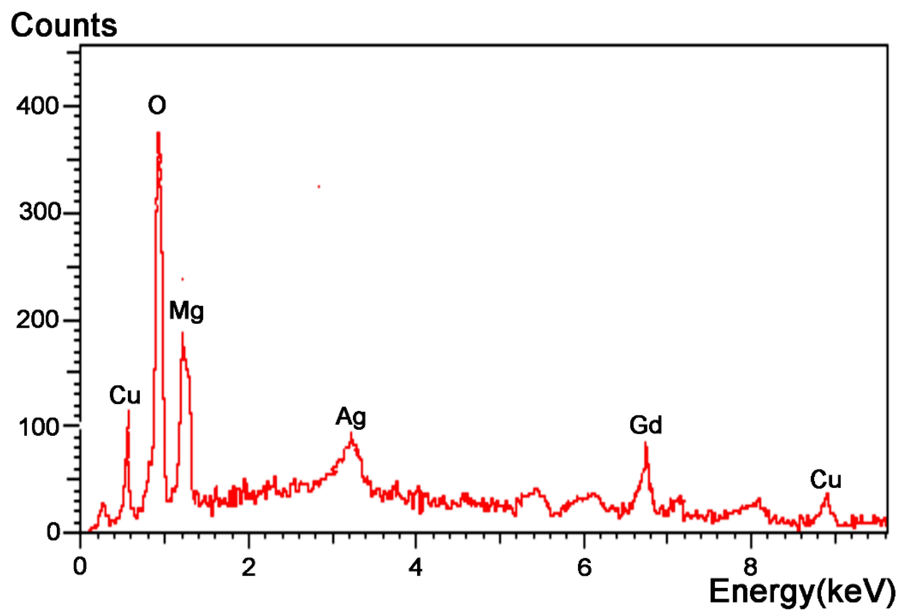
| Elements | O | Mg | Cu | Gd | Ag |
|---|---|---|---|---|---|
| Atomic content | 56.10 | 16.16 | 11.29 | 10.86 | 5.58 |
© 2019 by the authors. Licensee MDPI, Basel, Switzerland. This article is an open access article distributed under the terms and conditions of the Creative Commons Attribution (CC BY) license (http://creativecommons.org/licenses/by/4.0/).
Share and Cite
Lou, J.-F.; Cheng, A.-G.; Zhao, P.; Misra, R.D.K.; Feng, H. The Significant Impact of Carbon Nanotubes on the Electrochemical Reactivity of Mg-Bearing Metallic Glasses with High Compressive Strength. Materials 2019, 12, 2989. https://doi.org/10.3390/ma12182989
Lou J-F, Cheng A-G, Zhao P, Misra RDK, Feng H. The Significant Impact of Carbon Nanotubes on the Electrochemical Reactivity of Mg-Bearing Metallic Glasses with High Compressive Strength. Materials. 2019; 12(18):2989. https://doi.org/10.3390/ma12182989
Chicago/Turabian StyleLou, Jing-Feng, Ai-Guo Cheng, Ping Zhao, R. D. K. Misra, and Heng Feng. 2019. "The Significant Impact of Carbon Nanotubes on the Electrochemical Reactivity of Mg-Bearing Metallic Glasses with High Compressive Strength" Materials 12, no. 18: 2989. https://doi.org/10.3390/ma12182989