Fracture Characteristics and Analysis in Dissimilar Cu-Al Alloy Joints Formed via Electromagnetic Pulse Welding


Abstract
:
1. Introduction
2. Materials and Methods
3. Results and Discussion
3.1. Failure Mode and Fatigue Fracture Characteristics
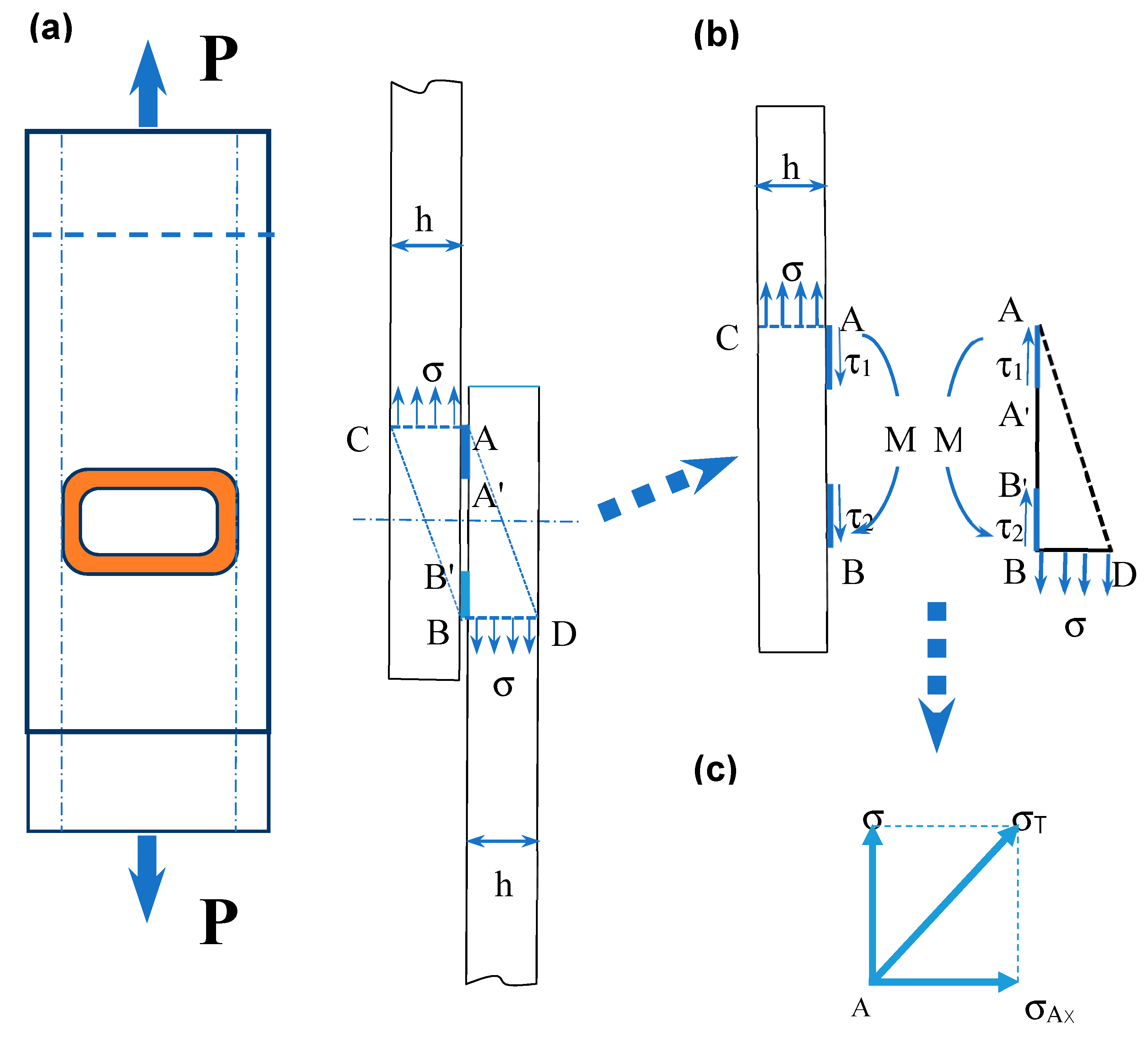
3.2. Stress Analysis and Calculation
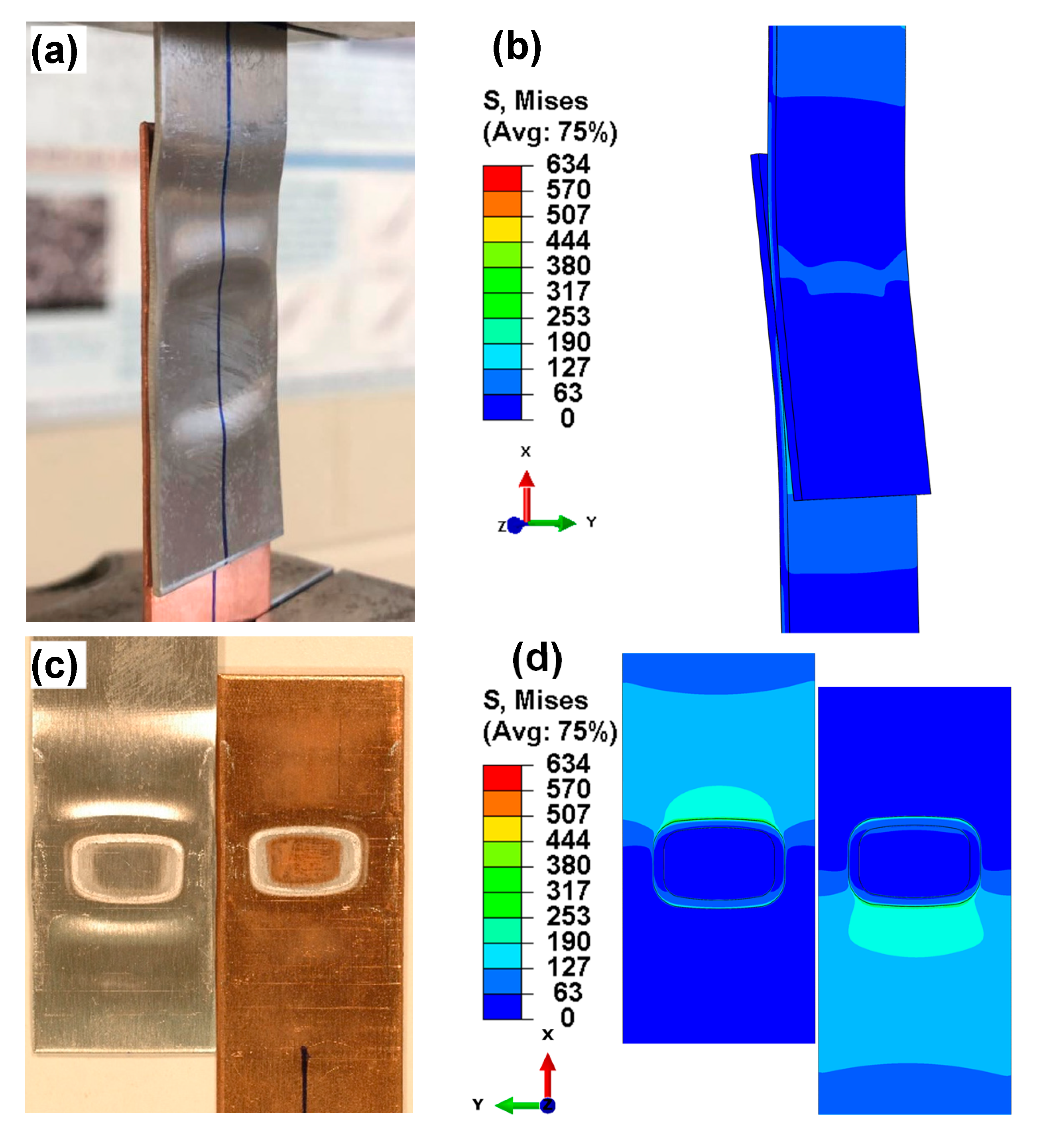
3.3. Finite Element Simulation
- (1)
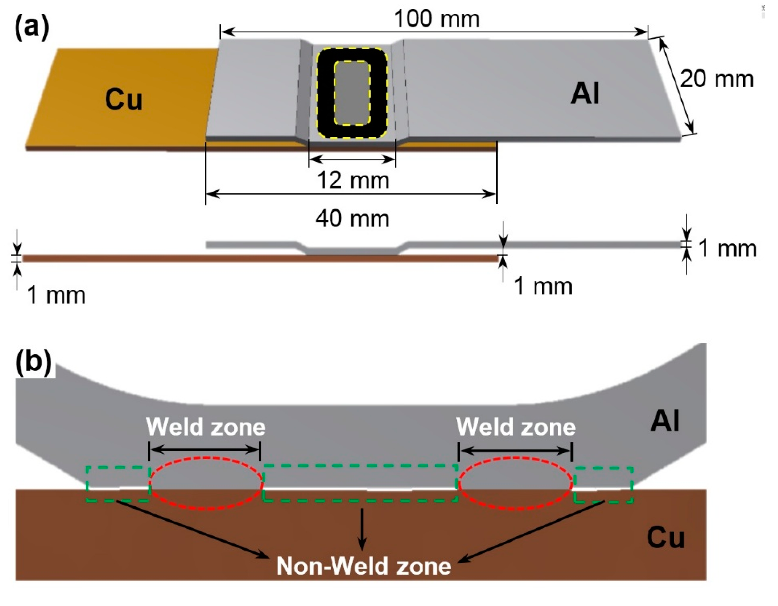
- The 3D finite element model was obtained based on actual sample sizes and joining condition of the lap welded joint as shown in Figure 1 and Figure 3, via EMPW with weld zones and non-weld zones (Figure 1); the thickness of welding layer and non-weld gap was assumed to be 0.05 mm to perform relatively accurate finite element simulation in the annular welding area.
- (2)
- The lap joint was well bonded with no defects, such as voids and cracks, located at the interface.
- (3)
- All the annular weld areas including transition zone of the joint had the same mechanical properties that were given in Table 3, which were obtained by the average values of the properties of 6061-O Al alloy and Cu.
- (4)
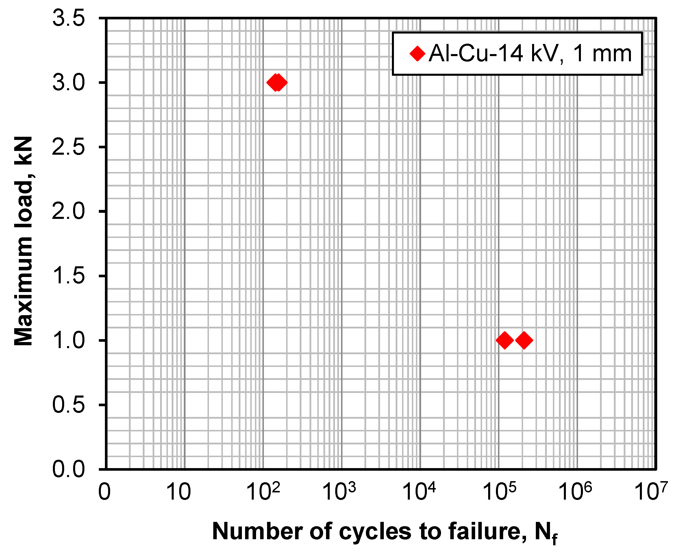
- A tensile load of 1 kN was applied in the finite element analysis to identify the stress distribution and stress concentration location, since the present fatigue loading was all tensile at a stress ratio of R = 0.2.
- (5)
- Clamping indentations were not considered in the finite element model.
4. Conclusions
- (1)
- Electromagnetic pulse welding gave rise to an annular (or ring-shaped) bonding area, with the weld zones and a central non-weld zone viewed on the cross section.
- (2)
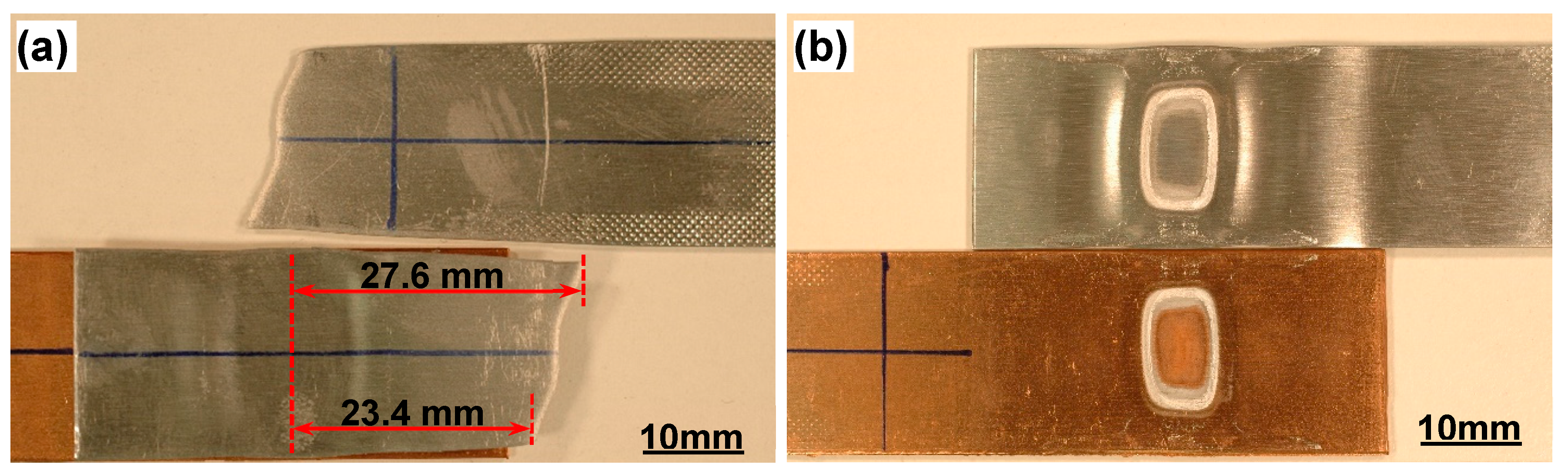
- Two types of failure modes were observed in relation to the applied cyclic loading levels. Base metal fracture or transverse through-thickness (TTT) crack growth occurred at a higher loading level, while interfacial failure occurred at a lower loading level.
- (3)
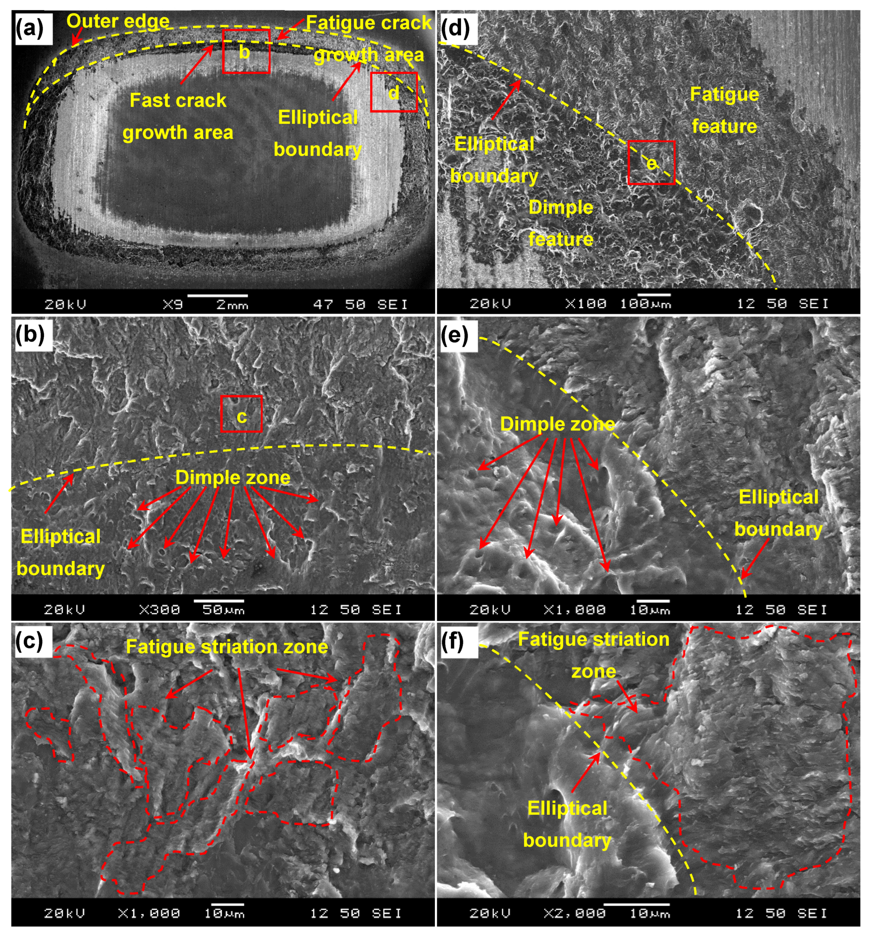
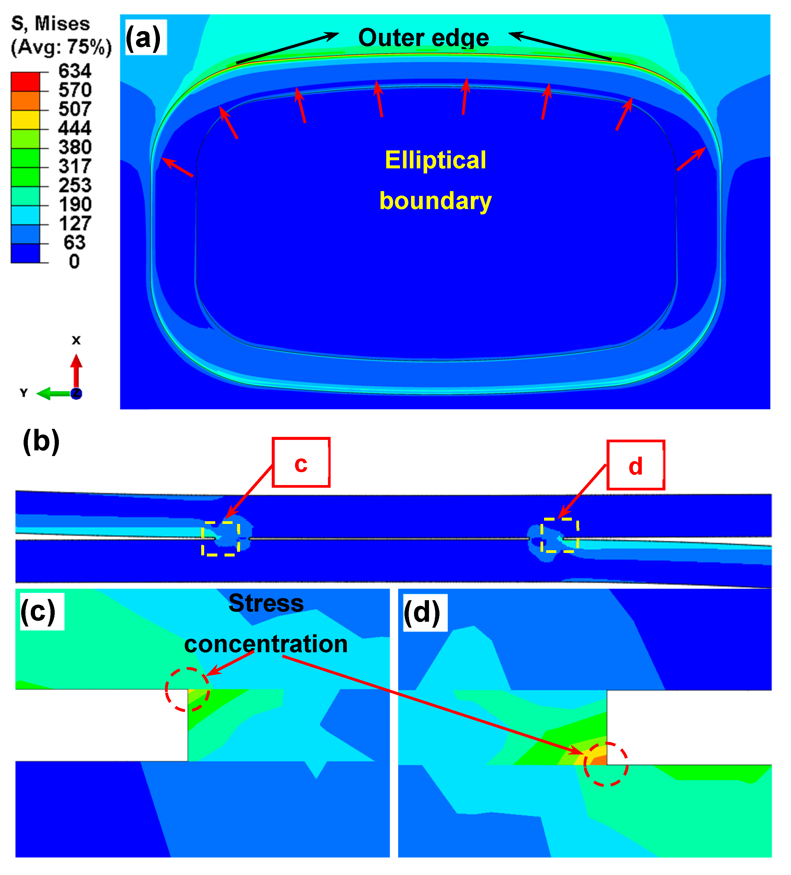
- In the interfacial failure, fatigue crack initiated from the outer edge of annular welding area, and propagated from the outer edge to form an approximate elliptical boundary. Fatigue crack propagation was characterized by fatigue striations present in discrete areas on the fracture surface. The final fast fracture started from elliptical boundary with some elongated shear dimples.
- (4)
- Both theoretical stress analysis and finite element model revealed that the maximum stress and stress concentration occurred along the outer edge, in accordance with the experimental observations of fatigue crack initiation site. The theoretical stress analysis also uncovered the existence of a normal stress due to the presence of bending moment caused by the inherent misalignment of a tensile lap shear sample. The combined role of the shear and normal stresses led to the formation of fatigue striations on the fracture surface.
Author Contributions
Funding
Acknowledgments
Conflicts of Interest
References
- Wu, X.; Shang, J. An investigation of magnetic pulse welding of Al/Cu and interface characterization. J. Manuf. Sci. Eng. 2014, 136, 051002. [Google Scholar] [CrossRef]
- McNutt, M. Climate change impacts. Science 2013, 341, 435. [Google Scholar] [CrossRef] [PubMed]
- Gielen, D.; Boshell, F.; Saygin, D. Climate and energy challenges for materials science. Nat. Mater. 2016, 15, 117–120. [Google Scholar] [CrossRef] [PubMed]
- Borbon-Almada, A.C.; Rodriguez-Muñoz, N.A.; Najera-Trejo, M. Energy and economic impact on the application of low-cost lightweight materials in economic housing located in dry climates. Sustainability 2019, 11, 1586. [Google Scholar] [CrossRef]
- Shi, Y.; Guo, H. Fatigue performance and fatigue damage parameter estimation of spot welded joints of aluminium alloys 6111-T4 and 5754. Fatigue Fract. Eng. Mater. Struct. 2013, 36, 1061–1090. [Google Scholar] [CrossRef]
- Honarpisheh, M.; Asemabadi, M.; Sedighi, M. Investigation of annealing treatment on the interfacial properties of explosive-welded Al/Cu/Al multilayer. Mater. Des. 2012, 37, 122–127. [Google Scholar] [CrossRef]
- Veerkamp, W.E. Copper-to-aluminum transitions in high DC bus systems. IEEE Trans. Ind. Appl. 1997, 33, 1027–1034. [Google Scholar] [CrossRef]
- Prangnell, P.; Haddadi, F.; Chen, Y.C. Ultrasonic spot welding of aluminium to steel for automotive applications—Microstructure and optimisation. Mater. Sci. Technol. 2011, 27, 617–624. [Google Scholar] [CrossRef]
- Das, H.; Jana, S.S.; Pal, T.K.; De, A. Numerical and experimental investigation on friction stir lap welding of aluminium to steel. Sci. Technol. Weld. Join. 2014, 19, 69–75. [Google Scholar] [CrossRef]
- Chen, S.; Daehn, G.S.; Vivek, A.; Liu, B.; Hansen, S.R.; Huang, J.; Lin, S. Interfacial microstructures and mechanical property of vaporizing foil actuator welding of aluminum alloy to steel. Mater. Sci. Eng. A 2016, 659, 12–21. [Google Scholar] [CrossRef]
- Ma, Z.Y.; Feng, A.; Chen, D.L.; Shen, J. Recent advances in friction stir welding/processing of aluminum alloys: Microstructural evolution and mechanical properties. Crit. Rev. Solid State Mater. Sci. 2018, 43, 269–333. [Google Scholar] [CrossRef]
- Mishra, R.; Ma, Z.Y. Friction stir welding and processing. Mater. Sci. Eng. R 2005, 50, 1–78. [Google Scholar] [CrossRef]
- Peng, H.; Chen, D.L.; Bai, X.F.; She, X.W.; Li, D.Y.; Jiang, X.Q. Ultrasonic spot welding of magnesium-to-aluminum alloys with a copper interlayer: Microstructural evolution and tensile properties. J. Manuf. Process. 2019, 37, 91–100. [Google Scholar] [CrossRef]
- Macwan, A.; Patel, V.; Jiang, X.Q.; Li, C.; Bhole, S.D.; Chen, D.L. Ultrasonic spot welding of Al/Mg/Al tri-layered clad sheets. Mater. Des. 2014, 62, 344–351. [Google Scholar] [CrossRef]
- Wang, S.Q.; Ma, T.J.; Li, W.Y.; Wen, G.D.; Chen, D.L. Microstructure and fatigue properties of linear friction welded TC4 titanium alloy joints. Sci. Technol. Weld. Join. 2017, 22, 177–181. [Google Scholar] [CrossRef]
- Wen, G.D.; Ma, T.J.; Li, W.Y.; Wang, S.Q.; Guo, H.Z.; Chen, D.L. Strain-controlled fatigue properties of linear friction welded dissimilar joints between Ti-6Al-4V and Ti-6.5Al-3.5Mo-1.5Zr-0.3Si alloys. Mater. Sci. Eng. A 2014, 612, 80–88. [Google Scholar] [CrossRef]
- Wang, H.M.; Wang, Y.L. High-velocity impact welding process: A review. Metals 2019, 9, 144. [Google Scholar] [CrossRef]
- Asemabadi, M.; Sedighi, M.; Honarpisheh, M. Investigation of cold rolling influence on the mechanical properties of explosive-welded Al/Cu bimetal. Mater. Sci. Eng. A 2012, 558, 144–149. [Google Scholar] [CrossRef]
- Mirza, F.A.; Macwan, A.; Bhole, S.D.; Chen, D.L.; Chen, X.G. Microstructure, tensile and fatigue properties of ultrasonic spot welded aluminum to galvanized high-strength-low-alloy and low-carbon steel sheets. Mater. Sci. Eng. A 2017, 690, 323–336. [Google Scholar] [CrossRef]
- Geng, H.; Mao, J.; Zhang, X.; Li, G.; Cui, J. Strain rate sensitivity of Al-Fe magnetic pulse welds. J. Mater. Process. Technol. 2018, 262, 1–10. [Google Scholar] [CrossRef]
- Liu, B.; Vivek, A.; Daehn, G.S. Joining sheet aluminum AA6061-T4 to cast magnesium AM60B by vaporizing foil actuator welding: Input energy, interface, and strength. J. Manuf. Process. 2017, 30, 75–82. [Google Scholar] [CrossRef]
- Macwan, A.; Kumar, A.; Chen, D.L. Ultrasonic spot welded 6111-T4 aluminum alloy to galvanized high-strength low-alloy steel: Microstructure and mechanical properties. Mater. Des. 2017, 113, 284–296. [Google Scholar] [CrossRef]
- Watanabe, M.; Kumai, S.; Hagimoto, G.; Zhang, Q.; Nakayama, K. Interfacial microstructure of aluminum/metallic glass lap joints fabricated by magnetic pulse welding. Mater. Trans. 2009, 50, 1279–1285. [Google Scholar] [CrossRef]
- ASTM E466-15—Standard practice for conducting force controlled constant amplitude axial fatigue tests of metallic materials; American Society for Testing and Material: Philadelphia, PA, USA, 2015.
- Xu, W.; Westerbaan, D.; Nayak, S.S.; Chen, D.L.; Goodwin, F.; Zhou, Y. Tensile and fatigue properties of fiber laser welded high strength low alloy and DP980 dual-phase steel joints. Mater. Des. 2013, 43, 373–383. [Google Scholar] [CrossRef]
- Xu, W.; Chen, D.L.; Liu, L.; Mori, H.; Zhou, Y. Microstructure and mechanical properties of weld-bonded and resistance spot welded magnesium-to-steel dissimilar joints. Mater. Sci. Eng. A 2012, 537, 11–24. [Google Scholar] [CrossRef]
- Peng, H.; Chen, D.L.; Jiang, X.Q. Microstructure and mechanical properties of an ultrasonic spot welded aluminum alloy: The effect of welding energy. Materials 2017, 10, 449. [Google Scholar] [CrossRef]
- Mohammed, S.M.A.K.; Dash, S.S.; Jiang, X.Q.; Li, D.Y.; Chen, D.L. Ultrasonic spot welding of 5182 aluminum alloy: Evolution of microstructure and mechanical properties. Mater. Sci. Eng. A 2019, 756, 417–429. [Google Scholar] [CrossRef]
- Rozumek, D.; Marciniak, Z. Fatigue tests of bimetal zirconium-steel made by explosive welding. Procedia Eng. 2016, 160, 137–142. [Google Scholar] [CrossRef]
- Peng, H.; Jiang, X.Q.; Bai, X.F.; Li, D.Y.; Chen, D.L. Microstructure and mechanical properties of ultrasonic spot welded Mg/Al alloy dissimilar joints. Metals 2018, 8, 229. [Google Scholar] [CrossRef]

| Material | Mg | Si | Cu | Mn | Fe | Zn | Ti | Cr | Ni | Al |
|---|---|---|---|---|---|---|---|---|---|---|
| 6061 O-Al alloy | 1.0 | 0.7 | 0.3 | 0.15 | 0.2 | 0.25 | 0.03 | 0.15 | 0.05 | Bal |
| Material | Bi | Sb | As | Fe | Pb | S | Cu |
|---|---|---|---|---|---|---|---|
| Copper T2 | 0.001 | 0.002 | 0.002 | 0.005 | 0.005 | 0.005 | ≥99.90 |
| Name | 6061-O Al Alloy | Copper T2 | Annular Shape Welding Area | |
|---|---|---|---|---|
| Properties | ||||
| Elastic modulus, E(GPa) | 69 | 120 | 95 | |
| Poisson ratio, ν | 0.33 | 0.34 | 0.33 | |
© 2019 by the authors. Licensee MDPI, Basel, Switzerland. This article is an open access article distributed under the terms and conditions of the Creative Commons Attribution (CC BY) license (http://creativecommons.org/licenses/by/4.0/).
Share and Cite
Wang, P.; Chen, D.; Ran, Y.; Yan, Y.; Peng, H.; Jiang, X. Fracture Characteristics and Analysis in Dissimilar Cu-Al Alloy Joints Formed via Electromagnetic Pulse Welding. Materials 2019, 12, 3368. https://doi.org/10.3390/ma12203368
Wang P, Chen D, Ran Y, Yan Y, Peng H, Jiang X. Fracture Characteristics and Analysis in Dissimilar Cu-Al Alloy Joints Formed via Electromagnetic Pulse Welding. Materials. 2019; 12(20):3368. https://doi.org/10.3390/ma12203368
Chicago/Turabian StyleWang, Puquan, Daolun Chen, Yang Ran, Yunqi Yan, He Peng, and Xianquan Jiang. 2019. "Fracture Characteristics and Analysis in Dissimilar Cu-Al Alloy Joints Formed via Electromagnetic Pulse Welding" Materials 12, no. 20: 3368. https://doi.org/10.3390/ma12203368