Article

A New Approach of Mathematical Analysis of Structure of Graphene as a Potential Material for Composites

Faculty of Mechanical Engineering, Lodz University of Technology, 90-924 Łódź, Poland
*
Author to whom correspondence should be addressed.
Materials 2019, 12(23), 3918; https://doi.org/10.3390/ma12233918
Submission received: 24 October 2019 / Revised: 16 November 2019 / Accepted: 22 November 2019 / Published: 27 November 2019
(This article belongs to the Special Issue Experimental and Numerical Investigation of Composite Materials)

Abstract

:
The new analysis of a simplified plane model of single-layered graphene is presented in this work as a potential material for reinforcement in ultralight and durable composites. However, owing to the clear literature discrepancies regarding the mechanical properties of graphene, it is extremely difficult to conduct any numerical analysis to design parts of machines and devices made of composites. Therefore, it is necessary to first systemize the analytical and finite element method (FEM) calculations, which will synergize mathematical models, used in the analysis of mechanical properties of graphene sheets, with the very nature of the chemical bond. For this reason, the considered model is a hexagonal mesh simulating the bonds between carbon atoms in graphene. The determination of mechanical properties of graphene was solved using the superposition method and finite element method. The calculation of the graphene tension was performed for two main directions of the graphene arrangement: armchair and zigzag. The computed results were verified and referred to articles and papers in the accessible literature. It was stated that in unloaded flake of graphene, the equilibrium of forces exists; however, owing to changes of inter-atom distance, the inner forces occur, which are responsible for the appearance of strains.

1. Introduction

The observed trend in “thinning” the parts of machines and devices as well as structural elements, especially in the aviation or armament industry (unmanned aerial, ground, or underwater vehicles), forces the development of new materials with particular emphasis on composites. Currently, in the world, a lot of attention is devoted to the potential use of graphene as a reinforcement matrix of polymer or polymer–carbon composites. It is assumed that the presence of dispersed graphene flakes will change the mechanics of system cracking. In the case of propagation of cracks and the potential impact of the fracture front with the encountered graphene structure, the energy will be dispersed according to the direction of spatial arrangement of the given graphene flake. This phenomenon can significantly improve the fracture toughness of the entire system, especially when operating in cryogenic conditions, for example, an unmanned aerial vehicle. However, the main problem of the design of composite elements reinforced with graphene is the enormous literature chaos associated with the mechanical parameters of the material, resulting mainly from the fact of projecting the graphene structure onto a lattice model, without taking into account the nature of the chemical bond. This fact undoubtedly makes it impossible to carry out a detailed finite element method (FEM) analysis enabling the design of the morphology and geometry of structural elements. For this reason, we first set up the systematization of mechanical parameters of graphene as an isolated material from the matrix of the composite.
The two-dimensional nature and carbon hybridization give graphene a unique set of properties, which are electrical [1,2,3], optical [4,5,6], and mechanical [7,8,9,10,11,12,13,14,15,16,17,18,19,20], practically unattainable for other engineering materials. While the optical and electrical research of graphene layers has been mostly perfected, defining the mechanical properties of the material leads to many technical issues, resulting from the nano-scale nature of graphene layers, which makes it impossible to conduct typical tests for the elongation. Any attempt to use nanotest or Atomic Force Microscope (AFM) [21,22,23] to characterize the mechanical properties is also disputable, owing to difficulties with sample mounting, which, in practice, is very difficult and complex. Such a process can also uncontrollably generate structural defects, which makes it very sensitive to mechanical damages [24]. In addition, graphene virtually cannot exist without a carrier in the form of a substrate, which also directly affects the final measurement result. An important factor is also the presence of physical interactions with CO, NO, NO2, and water vapor from the atmosphere with a graphene surface, which is not without significance and requires the stabilization of atmospheric composition on a level of ppm [25].
For this reason, a number of scientific centers have attempted to theoretically determine the mechanical properties of graphene [26]. These analyses, owing to the necessity of taking into account the multicriterial model, from both a physical and chemical point of view, are not devoid of defects, which, in the scientific literature, results in a multitude of incomparable results. Meo and Rossi [27] investigated the molecular mechanics of single-walled carbon nanotubes to predict the ultimate strength. Liu et al. [28] analyzed atomic bond breakage using a meshless atomic-scale method. With regard to the literature, many works were devoted to modeling of carbon nanotubes, which can be found in the literature [9,16,21,29,30,31,32,33,34,35,36,37,38,39,40,41,42,43,44,45]. One of them [33] can be here mentioned, where authors dealt with the mechanical properties of single-walled carbon nanotubes (SWCNTs) modeled as Euler beams. On the basis of the elastic deformation energy and mechanical equilibrium of single graphite sheet, they investigated Young’s modulus and Poisson’s ratio of such nanotubes.
The authors of [46,47] also investigated the fracture of nanotubes and a progressive fracture of nanotubes was developed in the work of [48]. From this point of view, the work deals with the simplified plate model of a graphene structure. In many analyses and investigations given in the literature, basic mechanical properties of graphene (Young’s modulus and Poisson’s ratio) were treated as the base for calculations. Both Young’s modulus and Poisson’s ratio in the elastic range are material constants; however, looking through literature, it is unknown how one should assume the values of those parameters for calculations of composite composed of matrixes and flaxes of graphene. As it is well known, graphene, with respect to its mechanical properties, among others, is being researched more and more in applications in the space vehicle and aviation industry, for example, as a structural composite material. However, first of all, it is necessary to systematize the data on the mechanical properties of graphene, which are clearly lacking in the literature. Among the articles concerning graphene, different mechanical properties are given: Young’s modulus Y = 1.2 TPa, 4.70 TPa, 6.6 TPa, 31.7 TPa, or even 86.5 TPa [41]. One should note that Young’s modulus of graphene flaxes treated as orthotropic material (assuming the homogenization) in almost all papers amounts to Y ≅ 1.0 ÷ 1.2 TPa, whereas Young’s modulus of graphene bars YGr is characterized by different values. Likely, the values of Poisson’s ratio are different and range, according to the literature, from 0.16 to 0.6. The results in some papers can also be incorrect, for example, in the work of [33], Poisson’s ratio equals 0.2, but following those equations, Poisson’s ratio equals νGr ≅ 0.49 ÷ 0.6. For the above reason, the author decide to developed an analytical model based on the theory of elasticity, assuming the incompressibility conditions that are used in continuity mechanics. The proposed model was validated by numerical calculation (finite element method software).

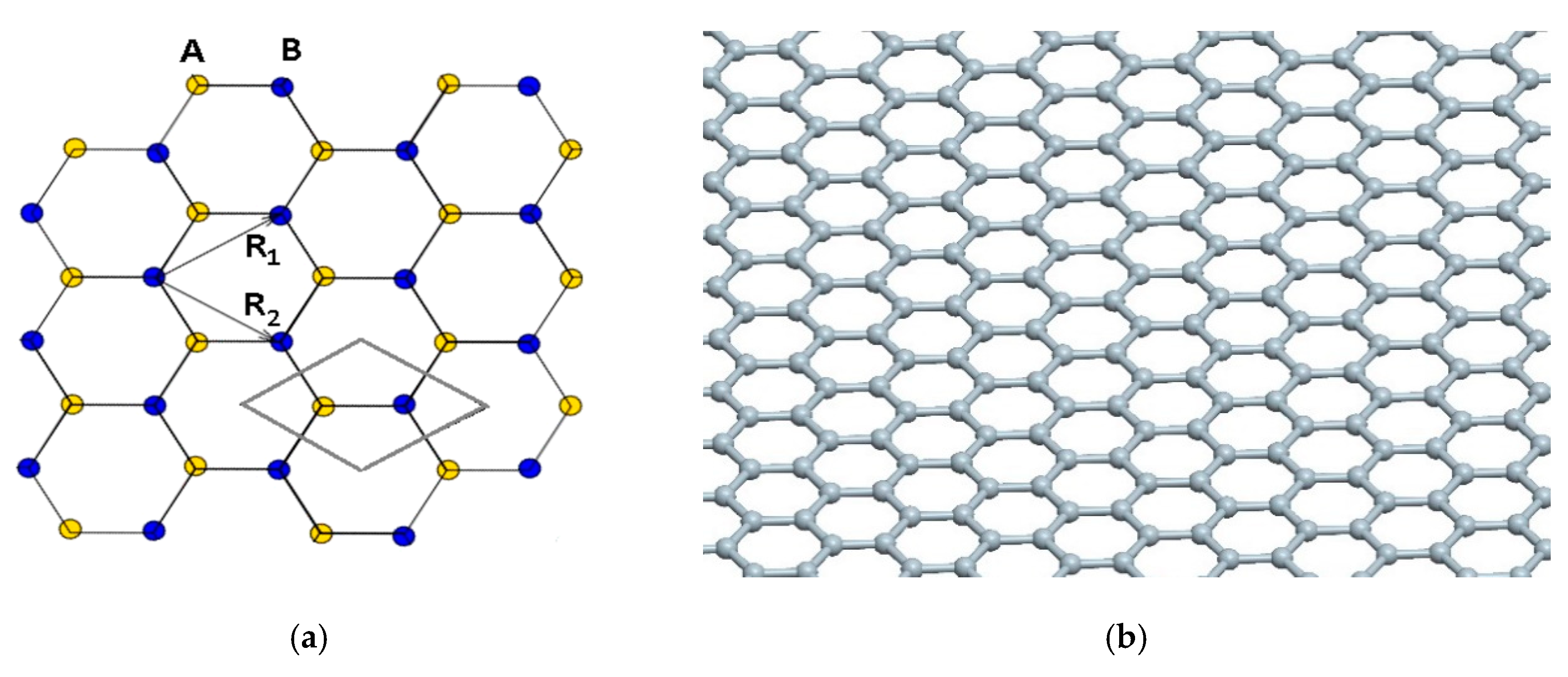
2. Assumptions for Modeling the Graphene Structure

In the present work, the analysis of the plane element of graphene consists of one layer of carbon atoms embedded in polymer matrix. The basic model was hexagonal mesh combining detailed atoms of graphene, which simultaneously are structural nodes (Figure 1). Similar to the classic method of strength analysis, bonds of graphene were stretched (continuous object was compared with the tension of the hexagonal mesh), which allowed the determination of Young’s modulus EGr and Poisson’s ratio ν for the graphene bar. The model is based on the ideal, chemically pristine structure of graphene, being a single layer of carbon atoms without any structural or chemical defects. We decided that any modelling based on a structure consisting of two or more graphene layers is not justified, as the presence of van der Waals interactions between them dramatically changes the properties of the material.
The analysis of the graphene tension was carried out for two basic directions (if the edge is cut-out along bonds between carbon atoms, one receives the “armchair” edge, otherwise the cutting-out in the perpendicular direction has the edge called “zigzag” [49]).
The model used for calculation was elaborated on the basis of the graphene structure given in other papers [27,29,32,50], among others (Figure 2). Young’s modulus of microstructure was assumed as Y = 1.15 TPa = 11.5 nN/Å2 (as in the works of [22,23,32,36,38]). The dimensions of the hexagonal mesh of graphene are presented in Figure 3; that is, l = 1.42 Å, a = 2.46 Å [50]. It was assumed that the thickness of the graphene sheet is the same as the diameters of carbon atom; however, different diameters were also taken into account. For comparison, the computations were conducted for three thicknesses of the graphene sheet (h = 0.44 Å; 0.75 Å; 0.89 Å and d = 0.44 Å; 0.75 Å; 0.89 Å, respectively). In the present work, it was assumed that the hexagonal structure can be divided into repeatable, “Y”-shaped elements interacting with each other through reactions (Figure 2a). For the simplified model, forces and strains were determined through tensions of the considered model. The basic literature states that graphene is a two-dimensional rhomb-shaped carbon mesh with a two-atom basis (Figure 1a).
Young’s modulus determined on the basis of data from the literature [16,19,21,25,27,32] for the continuous structure of graphene, Y= 1.15 TPa [16], but Young’s modulus for the polymer matrix amounts to Em = 3.5 GPa. Thus, with respect to large difference in stiffnesses, the stresses carried by the matrix, this parameter can be omitted (ratio of Young’s moduli of matrix to graphene is Em/Y = 0.003). The tension stresses of elementary distance with dimensions a, h and 3/4l amount to σx = ε y ( 1 ) Y = 1.15 GPa, but the total force F = Fx acting in the repeatable element of structure is determined by the following:
F x = ε x ( 1 ) · Y · a · h .
with the assumptions of average Young’s modulus of the considered part of graphene Yave = Y, one can calculate the force F x affecting repeatable elements of the structure. For example, for strain ε Y ( 1 ) = 0.001, the Y = 1.15 TPa, a = 2.46 Å, and h = 0.75 Å force is as follows:
F x = ε x ( 1 ) · Y · a · h = 2.122 · 10 2 n N .

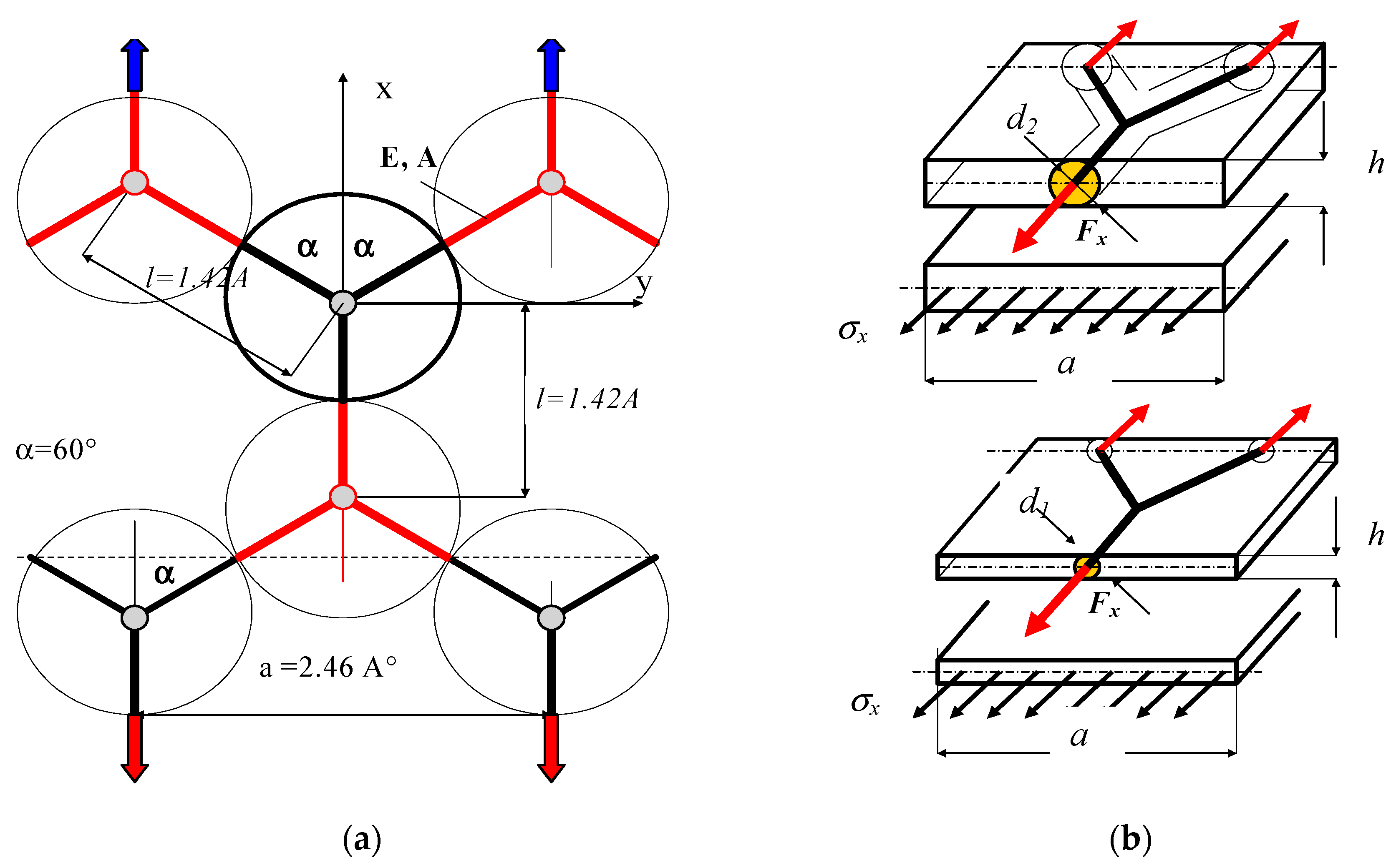
3. Basic Model of Graphene Cell (Calculations of Strains)

To simplify, substituting continuous elementary segments of graphene by the bar system, it was assumed that the schematic model includes interactions between atoms in the graphene owing to tensions and bending (Figure 4). The shown segment of graphene in the Y-shape can be treated as a macroelement of the graphene structure.
The elongations of system owing to tension are as follows:
Δ L = F x · l 2 E G r · A ;   Δ N = F x · l / 2 4 E G r · A ;   Δ L + Δ N 2 = 9 F · l 16 E G r · A .
The elongations of system owing to bending can be written as follows:
f b = F x · 3 4 ( l 2 ) 3 3 · E G r · J = F x 3 4 · l 3 24 E G r · J   ;   f s = ψ ( 1 + ν ) F x 3 4 · l E G r · A ; f c = f b + f s = F x 3 4 ( l 3 24 E G r · J + ψ ( 1 + ν ) l E G r · A ) ,
where A and J represent the cross-section area and moment of inertia of the graphene bar, respectively. The magnitude ψ denotes the coefficient regarding the influence the shear stresses during strains of the graphene bars (ψ = 1.2). Taking into account both effects, total elongation can be written as follows:
Δ l c = Δ L + 1 2 Δ N + 3 2 f c = 9 F · l 16 E · A + 3 F 8 ( l 3 24 E · J + ψ ( 1 + ν ) l E · A ) .
The strain in the x-direction of the segment caused by bending and tension is expressed as follows:
ε x ( 1 ) = 4 3 l ( Δ L + 1 2 Δ N + 3 2 f c ) .
By transforming the strain in the x-direction, one obtains the following:
ε x ( 1 ) = F x 4 E G r ( l 2 12 J + 3 + 2 ψ ( 1 + ν ) A ) .
The elongation of the segment of the graphene structure at the length of Ls = ¾ l is as follows:
Δ l c = ε x ( 1 ) · L s = F x 4 E G r ( l 2 12 J + 3 + 2 ψ ( 1 + ν ) A ) · L s .
The strain of the alternative segment of the graphene structure with dimensions a, h and length L is as follows:
ε x ( 2 ) = F x Y · a · h .
With the assumption of the bar structure of graphene and substitution of the repeatable element of structure by rectangular shape, one can compare both strains ε Y ( 1 ) = ε Y ( 2 ) . It was assumed that the strains of repeatable of the graphene structure are the same as the continuous structure of graphene with dimensions a, h and length Ls. Young’s modulus was taken from the literature [22,32,38] as EGr = Y = 1.15 TPa = 11.5 nN/Å2. Hence, substituting Young’s modulus of graphene is determined as follows:
E G r = Y · a · h 4 ( l 2 12 · J + 3 + 2 ψ ( 1 + ν ) A ) .
In this same way as above, the strain in the perpendicular direction was obtained:
ε y ( 1 ) = F x 4 E G r ( l 2 12 · J + 2 ψ ( 1 + ν ) 1 A ) .
On the basis of Equations (7) and (11), the substitute Poisson’s ratio of hexagonal structure of graphene can be calculated as follows:
ν G r ( 1 ) = ε x ( 1 ) ε y ( 1 ) .
By transforming Equation (11), the force of repeatable element of structure for given strain can be calculated as follows:
F x = 4 ε x ( 1 ) · E G r l 2 12 J + 2 ψ ( 1 + ν ) + 3 A .

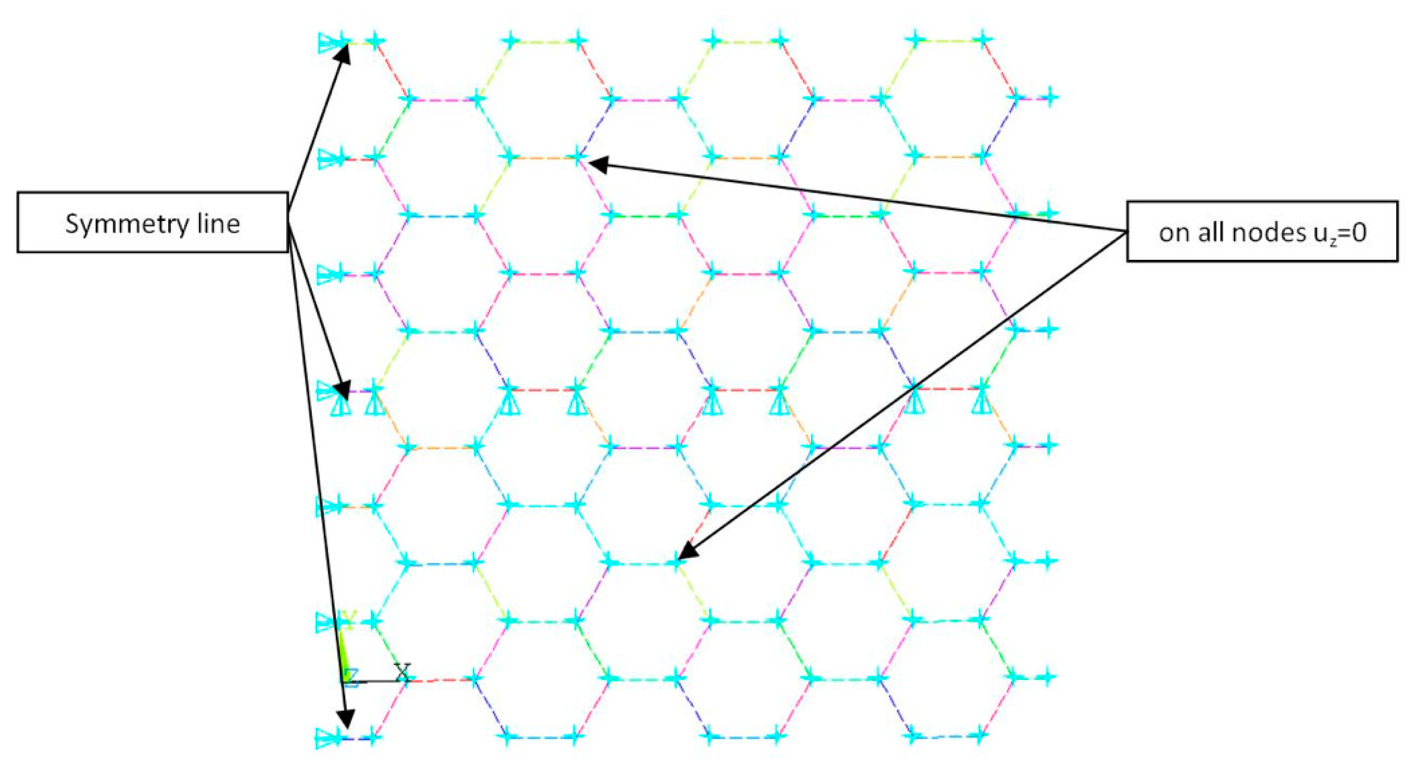
4. Numerical Model of Graphene Band

The numerical model of graphene was discussed in many works [28,30,32,47], among others. For the aim of the verification of the assumed macroelement of graphene structure shown in Figure 4, numerical calculation using the finite element method (ANSYS v.18.2 software—Figure 3) was executed.
The mesh of the graphene structure was created by a two-node element beam. The dimensions of numerical model were Lx = 14.91 Å, Ly = 14.76 Å, and different diameters of bar (see results in Table 1). Numerical models of the segment of the graphene band subjected to tension in the x-direction and y-direction were displayed in Figure 5a (armchair) and Figure 5b (zigzag), respectively.

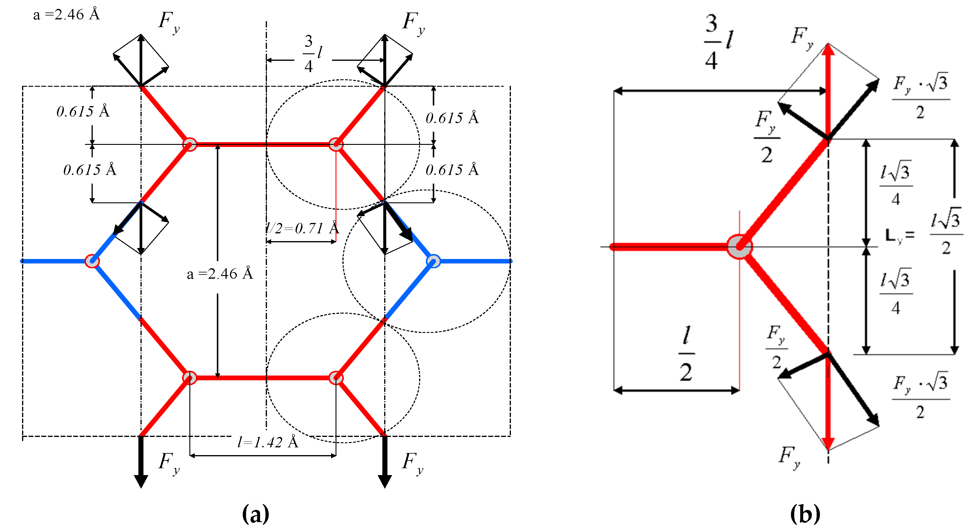
5. The Strain in y-Direction

Treating the segment of graphene as the basic element for the analysis of forces and strains of the structure, calculations of strains for tension in the y-direction were conducted. In this case, the band of graphene has the “zigzag”-type edge. Owing to the fact that graphene is an anisotropic structure, analogous analysis of strains, as done previously, but in the y-direction, was carried out. The scheme of acting forces on the repeatable element of the graphene structure is displayed in Figure 6a.
The strain for load in the y-direction, perpendicular to the x-axis, is presented in Figure 7b. The lines associating atoms passing through the line are called zigzags (Figure 6b). Initially, the simplified estimations were performed, provided that forces in horizontal elements are forces between atoms. Thus, their influence on strains in the perpendicular direction, with respect to the direction of load, can be defined on the basis of the strain of the graphene band. The elongation of the cut-out structure at the length of L y = l 3 2 amounts to Δ l y = ε y · L y . However, the strain of the substitute segment with dimensions b, h and Ly is described as follows:
ε y ( 3 ) = F y Y · b · h .
With assumption of bar structure of the graphene and substitution of the repeatable element of the structure by cubic element, strains of both models were compared, where b = ¾ l. The strain owing to load in the y-direction is given as follows:
ε y ( 4 ) = F y 2 3 · E G r ( l 2 12 · J + 3 + 2 ψ ( 1 + ν ) A ) .
Further, the strain in the perpendicular direction regarding loading is formulated as follows:
ε x ( 4 ) = F y 2 3 · E G r ( l 2 12 · J + 2 ψ ( 1 + ν ) 1 A ) .
Considering tensile element by forces Fy and comparing longitudinal and lateral strains, the substitute Poisson’s ratio is determined as follows:
ν G r ( 2 ) = ε x ( 4 ) ε y ( 4 ) .
Young’s modulus in the case of tension in the y-direction was calculated using the following equation:
ε x ( 4 ) = F y 2 3 · E G r ( l 2 12 J + 2 ψ ( 1 + ν ) 1 A ) ,
E G r = 3 l · h · Y 2 3 ( l 2 24 J + 3 + 2 ψ ( 1 + ν ) 2 A ) .
If Young’s modulus for the bar of graphene is known, the modulus for the sheet of graphene can be calculated as follows:
Y = 3 · E G r h ( l 2 16 J + 9 + 6 ψ ( 1 + ν ) 2 A l ) .
By omitting coefficient ψ, identical results as in the work of [33] can be obtained. Coefficient ψ takes into account the influence of shear stress on the value of beam deflection, which represents a model of the chemical bond between carbon atoms [51].

6. Results

On the basis of the above relations (Equation (10); Equation (12), lines 1–7; and Equation (17), lines 8–14), Young’s modulus of the graphene bar EGr and substitute Poisson’s ratio for the hexagonal structure of graphene were computed. Those values are set out in Table 1. The first seven lines in the table refer to the x-direction of tension (“armchair”), whereas the next seven lines relate to the y-direction of tension (“zigzag”).
For the purpose of comparison, calculations for seven thicknesses of the graphene sheet (Table 1) were executed. On the basis of the above relations (Equation (10) and (12)), Young’s modulus of the graphene bar EGr and substitute Poisson’s ratio of the hexagonal structure were estimated. These values are included in Table 1. It should be mentioned that, in another paper [18], Poisson’s ratio of graphene was given as 0.06, 0.19, and 0.22–0.55. In the present paper, for all determined cases (FEM), Poisson’s ratio ranges from 0.373 (“zigzag”) to 0.812 (“armchair”), but these values are still significantly greater than 0.2. Thus, it should be verified which factors have an influence on the strain in the perpendicular direction to tension. It is a question of whether forces between atoms blocking excessive narrowing incompatible with real lateral shortening of graphene should be considered. This phenomenon cannot be caused owing to the presence of a matrix, because the ratio of Young’s moduli of both materials amounts to 0.003. For example, the diameter of the graphene bar and thickness of the sheet equals 0.75Å, and Young’s modulus EGr of elementary segment consisting of the graphene bar amounts to 13.09 TPa. However, the Poisson’s ratio determined according to the above relation (Equation (12) and (17)) is equal to 0.63 and does not correspond to the real value obtained empirically (νexp = 0.19–0.22). Moreover, this value is greater than 0.5 (limit value assumed usually for a solid). Therefore, it is interesting if the assumed scheme of the graphene band with omitting forces between atoms responds to the real graphene. It can be assumed that, for the decrease of strain in the perpendicular direction, inner forces in the atom structure are responsible. Poisson’s ratios obtained in an analytical and numerical way for some mechanical properties are comparable (cf: Table 1, line 2). Maps of displacements of the graphene mesh are displayed in Figure 7a (x-direction) and Figure 7b (y-direction).

7. Strains in Both Directions

As stated in the previous subsection, obtaining Poisson’s ratio on the level of 0.2, in both a numerical and an analytical way, is impossible. Hence, apparently, the interaction between graphene atoms should be taken into account, which in practise can be very difficult. Using superposition of forces’ action in both directions (Figure 8), the ratio of forces for Poisson’s ratio can be found.
On the basis of the superposition rule, the value of Poisson’s ratio attributable to both tension forces Fy and Fx simultaneously equals the following:
ν x y = ε y ε x = ε y ( 1 ) + ε y ( 4 ) ε x ( 1 ) + ε x ( 4 ) .
After taking into consideration previously derived relations (Equations (7), (11), (15), (18)), the Poisson’s ratio dependent upon tension forces can be written as follows:
ν x y = F x 2 E G r ( 1 ) ( l 2 12 J + 2 ψ ( 1 + ν ) 1 A ) + F y 3 · E G r ( 2 ) ( l 2 12 J + 2 ψ ( 1 + ν ) + 3 A ) F x 2 E G r ( 1 ) ( l 2 12 J + 2 ψ ( 1 + ν ) + 3 A ) F y 3 · E G r ( 2 ) ( l 2 12 J + 2 ψ ( 1 + ν ) 1 A ) .
Introducing the ratio of forces as follows:
k x y = F y F x ,
and by transforming Equation (22), the ratio kxy can be determined as follows:
k x y = 3 E G r ( 2 ) 2 E G r ( 1 ) ( l 2 12 J + 2 ψ ( 1 + ν ) 1 A ) ν x y ( l 2 12 J + 2 ψ ( 1 + ν ) + 3 A ) ( l 2 12 J + 2 ψ ( 1 + ν ) + 3 A ) ν x y ( l 2 12 J + 2 ψ ( 1 + ν ) 1 A ) .
For example, to obtain Poisson’s ratio equal to 0.215 in the range of proportionality, and taking the data of graphene, kxy should equal 0.433 (notice the ratio of forces as well). Hence, it can be concluded that it is necessary to consider the interaction between the graphene atoms, introducing additional bars in the mathematical model of graphene, which is the aim of further work of the authors.

8. Summary

In the present work, the new simplified model of the plane graphene structure was investigated. In it, numerous analyses and studies included in the literature of basic mechanical properties (Young’s modulus and Poisson’s ratio) of graphene were presented. The basic model that was used was a hexagonal mesh associated with detailed atoms of graphene, which were simultaneously nodes. The issue was solved on the basis of the superposition method. As in the classic method of the strength analysis, the easy tension of the graphene band (continuous medium was compared with the tension of the hexagonal mesh) was considered to determine the mechanical properties of bars of the mesh. The study of tension was performed for two basic directions (for the “armchair” and “zigzag” direction). It turned out that, for the analytical and numerical calculations, the relations between Young’s moduli of continuous graphene structure and hexagonal structure relate to homogenization principals established in the theory of orthotropic medium. However, the value of Poisson’s ratio of hexagonal mesh does not correspond to values of 0.06, 0.19, and 0.22–0.55, approved in the literature [18]. Also, in the work of [18], it was stated that Poisson’s ratio of graphene can be greater and close to 1.0; therefore, the value of 0.6 is not the special case. Nevertheless, the presented model for calculation should be modified to respond to the real graphene structure. In the unloaded flax of the graphene structure, equilibrium between atoms exists. During tension, owing to changes in the distance between atoms, the forces of atoms’ interaction take different values and have an influence on the strain of graphene. In the case of nanotubes, the graphene mesh constitutes the closed circumference, which essentially disturbs the determination of the forces between atoms. However, in the case of the tensed band on the edges, non-zero forces act. The load by those forces on the edges of the bands of graphene enables the simplified analysis of strain of graphene structure. The values of those forces can be approximately determined for stretched segment along the zigzag edge. The issue concerning mathematical analysis of interaction between graphene atoms requires deeper research and will be a subject of further work of authors, especially with regard to graphene as a reinforcement of composite materials, in the case in which it will also be necessary to consider physicochemical interactions at the boundary of polymer matrix and a reinforcement in the form of graphene.

Author Contributions

Methodology, M.J., L.C., Ł.K. and T.W.; formal analysis, M.J. and L.C.; investigation, M.J., L.C. and Ł.K.; validation, M.J., L.C., Ł.K. and T.K.; writing—original draft, M.J., L.C. and Ł.K.; writing—review & editing, L.C., Ł.K., T.K. and T.W.; supervision—T.K.

Funding

This research received no additional funding.

Conflicts of Interest

The authors declare no conflict of interest.

Nomenclature

a Dimension between atoms bond
l Length of graphene bar
d Diameter of graphene bar
h Thickness of single graphene sheet for one layer
L s Length of segment
F x Tension force for armchair edge (x-direction)
F y Tension force for zigzag edge (y-direction)
α Angle between graphene bar
Δ N Increment of elongation of segment caused by tension
Δ l Increment of elongation of bar
f c Total elongation caused by bending
Y Young’s modulus of segment of graphene sheet
E Gr Young’s modulus of graphene bar
J Moment of inertia of graphene bar
A Cross-section area
Δ l t Total increment of elongation due to bending and tension
L s Length of graphene segment
ν Poisson’s ratio for graphene bar
ν Gr ( 1 ) Poisson’s ratio for graphene cut-out for x-direction
ν Gr ( 2 ) Poisson’s ratio for graphene cut-out for y-direction
ε x ( 1 ) Strain of segment in x-direction caused by tension and bending in x-direction
ε y ( 1 ) Strain of segment in y-direction caused by tension and bending in x-direction
ε x ( 2 ) Strain in x-direction of alternative segment in x-direction
ε y ( 4 ) Strain of segment in y-direction caused by tension and bending in y-direction
ε x ( 4 ) Strain of segment in x-direction caused by tension and bending in y-direction
ε y ( 3 ) Strain in y-direction of alternative segment in y-direction
νxyPoisson’s ratio of graphene calculated for two perpendicular forces
kxyRatio of forces

References

  1. Zhou, B.L.; Zhou, B.H.; Chen, X.W.; Zhou, G.H.; Zhou, G. Electronic transport for impurity-doped armchair-edge graphene nanoribbons. Eur. Phys. J. B 2012, 85, 85–121. [Google Scholar] [CrossRef]
  2. Shin, S.; Kim, J.; Kim, J.H.; Kim, S.I. Enhanced performance of organic light-emitting diodes by using hybrid anodes composed of graphene and conducting polimer. Curr. Appl. Phys. 2013, 13, 144–147. [Google Scholar] [CrossRef]
  3. Atabaki, M.M.; Kovacevic, R. Graphene composites as anode materials in lithium-ion batteries. Electron. Mater. Lett. 2013, 9, 133–153. [Google Scholar] [CrossRef]
  4. Liu, Z.; Zhang, X.; Yan, X.; Chen, Y.; Tian, J. Nonlinear optical properties of graphene-based materials. Chin. Sci. Bull. 2012, 57, 2971–2982. [Google Scholar] [CrossRef]
  5. Yamuna, R.; Ramakrishnan, S.; Dhara, K.; Devi, R.; Kothurkar, N.K.; Kirubha, E.; Palanisamy, P.K. Synthesis, characterization, and nonlinear optical properties of graphene oxide functionalized with tetra-amino porphyrin. J. Nanopart. Res. 2013, 15, 1399. [Google Scholar] [CrossRef]
  6. Yang, Y.E.; Yang, Y.R.; Yan, X.H. Universal optical properties of graphene nanoribbons: A first-principles study. Phys. E Low Dimens. Syst. Nano Struct. 2012, 44, 1406–1409. [Google Scholar] [CrossRef]
  7. Gao, Y.; Hao, P. Mechanical properties of monolayer graphene under tensile and compressive loading. Phys. E Low Dimens. Syst. Nanostruct. 2009, 41, 1561–1566. [Google Scholar] [CrossRef]
  8. Ferralis, N. Probing mechanical properties of graphene with Raman spectroscopy. J. Mater. Sci. 2010, 45, 5135–5149. [Google Scholar] [CrossRef]
  9. Xiao, J.R.; Staniszewski, J.; Gillespie, J.W., Jr. Tensile behaviors of graphene sheets and carbon nanotubes with multiple Stone–Wales defects. Mater. Sci. Eng. A 2010, 527, 715–723. [Google Scholar] [CrossRef]
  10. Park, H.J.; Meyer, J.; Roth, S.; Skákalová, V. Growth and properties of few-layer graphene prepared by chemical vapor deposition. Carbon 2010, 48, 1088–1094. [Google Scholar] [CrossRef]
  11. Georgantzinos, S.; Giannopoulos, G.; Anifantis, N.; Georgantzinos, S. Numerical investigation of elastic mechanical properties of graphene structures. Mater. Des. 2010, 31, 4646–4654. [Google Scholar] [CrossRef]
  12. Ni, Z.; Bu, H.; Zou, M.; Yi, H.; Bi, K.; Chen, Y. Anisotropic mechanical properties of graphene sheets from molecular dynamics. Phys. B Condens. Matter 2010, 405, 1301–1306. [Google Scholar] [CrossRef]
  13. Soldano, C.; Mahmood, A.; Dujardin, E. Production, properties and potential of graphene. Carbon 2010, 48, 2127–2150. [Google Scholar] [CrossRef]
  14. Kula, P.; Szymanski, W.; Kolodziejczyk, L.; Atraszkiewicz, R.; Grabarczyk, J.; Clapa, M.; Kaczmarek, L.; Jedrzejczak, A.; Niedzielski, P. High strength metallurgical graphene for hydrogen storage nanocomposites. Vacuum 2016, 129, 79–85. [Google Scholar] [CrossRef]
  15. Kula, P.; Kaczmarek, L.; Zawadzki, P.; Kołodziejczyk, L.; Szymanski, W.; Niedzielski, P.; Pietrasik, R.; Dybowski, K.; Kazimierski, D.; Nowak, D. Functionality of graphene as a result of its heterogenic growth on SiC nanoparticles on the basis of reversible hydrogen storage. Int. J. Hydrogen Energy 2014, 39, 19662–19671. [Google Scholar] [CrossRef]
  16. Tu, Z.C.; Ou-Yang, Z.C. Single-walled and multi-walled carbon nanotubes viewed as elastic tubes with the effective Young’s moduli dependent on layer number. Phys. Rev. B 2002, 65, 233407. [Google Scholar] [CrossRef]
  17. Meguid, S.; Wernik, J.; Cheng, Z. Atomistic-based continuum representation of the effective properties of nano-reinforced epoxies. Int. J. Solids Struct. 2010, 47, 1723–1736. [Google Scholar] [CrossRef]
  18. Zhao, P.; Shi, G. Study of poisson’s ratios of graphene and single-walled carbon nanotubes based on an improved molecular structural mechanics model. SL 2011, 5, 49–58. [Google Scholar]
  19. Zhao, H.; Min, K.; Aluru, N.R. Size and Chirality Dependent Elastic Properties of Graphene Nanoribbons under Uniaxial Tension. Nano Lett. 2009, 9, 3012–3015. [Google Scholar] [CrossRef]
  20. Baykasoglu, C.; Kirca, M.; Mugan, A. Nonlinear failure analysis of carbon nanotubes by using molecular-mechanics based models. Compos. Part B Eng. 2013, 50, 150–157. [Google Scholar] [CrossRef]
  21. Frank, I.W.; Tanenbaum, D.M.; Van Der Zande, A.M.; McEuen, P.L. Mechanical properties of suspended graphene sheets. J. Vac. Sci. Technol. B. 2007, 25, 2558–2561. [Google Scholar] [CrossRef]
  22. Cao, G. Atomistic Studies of Mechanical Properties of Graphene. Polymers 2014, 6, 2404–2432. [Google Scholar] [CrossRef]
  23. Akinwande, D.; Brennan, C.J.; Bunch, J.S.; Egberts, P.; Felts, J.R.; Gao, H.; Huang, R.; Kim, J.S.; Li, T.; Li, Y.; et al. A review on mechanics and mechanical properties of 2D materials—Graphene and beyond. Extrem. Mech. Lett. 2017, 13, 42–77. [Google Scholar] [CrossRef]
  24. Tian, W.; Li, W.; Yu, W.; Liu, X. A Review on Lattice Defects in Graphene: Types, Generation, Effects and Regulation. Micromachines 2017, 8, 163. [Google Scholar] [CrossRef]
  25. Peng, Q.; Chen, Z.; De, S. A Density Functional Theory Study of the Mechanical Properties of Graphane with van der Waals Corrections. Mech. Adv. Mater. Struct. 2015, 22, 717–721. [Google Scholar] [CrossRef]
  26. Kvashnin, A.G.; Sorokin, P.B.D.; Kvashnin, G. The Theoretical Study of Mechanical Properties of Graphene Membranes. Fuller. Nanotub. Carbon Nanostruct. 2010, 18, 497–500. [Google Scholar] [CrossRef]
  27. Meo, M.; Rossi, M. A molecular-mechanics based finite element model for strength prediction of single wall carbon nanotubes. Mater. Sci. Eng. A 2007, 454, 170–177. [Google Scholar] [CrossRef]
  28. Liu, B.; Huang, Y.; Jiang, H.; Qu, S.; Hwang, K.C. The atomic-scale finite element method. Comput. Methods Appl. Mech. Eng. 2004, 193, 1849–1864. [Google Scholar] [CrossRef]
  29. Wernik, J.M.; Meguid, S.A. Recent Developments in Multifunctional Nanocomposites Using Carbon Nanotubes. Appl. Mech. Rev. 2010, 63, 050801. [Google Scholar] [CrossRef]
  30. Liu, B.; Jiang, H.; Huang, Y.; Qu, S.; Yu, M.F.; Hwang, K.C. Atomic-scale finite element method in multiscale computation with applications to carbon nanotubes. Phys. Rev. B 2005, 72, 035435. [Google Scholar] [CrossRef]
  31. Song, Y.S.; Youn, J.R. Modeling of effective elastic properties for polymer based carbon nanotube composites. Polymer 2006, 47, 1741–1748. [Google Scholar] [CrossRef]
  32. Meo, M.; Rossi, M. Prediction of Young’s modulus of single wall carbon nanotubes by molecular-mechanics based finite element modelling. Compos. Sci. Technol. 2006, 66, 1597–1605. [Google Scholar] [CrossRef]
  33. Lei, X.; Natsuki, T.; Shi, J.; Ni, Q.Q. Analysis of Carbon Nanotubes on the Mechanical Properties at Atomic Scale. J. Nanomater. 2011, 2011, 805313. [Google Scholar] [CrossRef] [Green Version]
  34. Parvaneh, V.; Shariati, M.; Torabi, H. Bending buckling behavior of perfect and defective single-walled carbon nanotubes via a structural mechanics model. Acta Mech. 2012, 223, 2369–2378. [Google Scholar] [CrossRef]
  35. Tserpes, K.; Papanikos, P.; Labeas, G.; Pantelakis, S. Multi-scale modeling of tensile behavior of carbon nanotube-reinforced composites. Theor. Appl. Fract. Mech. 2008, 49, 51–60. [Google Scholar] [CrossRef]
  36. Tserpes, K.; Papanikos, P. The effect of Stone–Wales defect on the tensile behavior and fracture of single-walled carbon nanotubes. Compos. Struct. 2007, 79, 581–589. [Google Scholar] [CrossRef]
  37. Mohammadpour, E.; Awang, M. Predicting the nonlinear tensile behavior of carbon nanotubes using finite element simulation. Appl. Phys. A 2011, 104, 609–614. [Google Scholar] [CrossRef]
  38. Wernik, J.M.; Meguid, S.A. Atomistic-based continuum modeling of the nonlinear behaviour of carbon nanotubes. Acta Mech. 2010, 212, 167–179. [Google Scholar] [CrossRef]
  39. Xiao, J.R.; Staniszewski, J.; Gillespie, J.W. Fracture and progressive failure of defective graphene sheets and carbon nanotubes. Compos. Struct. 2009, 88, 602–609. [Google Scholar] [CrossRef]
  40. Rao, P.S.; Anandatheertha, S.; Naik, G.N.; Gopalakrishnan, S. Estimation of mechanical properties of single wall carbon nanotubes using molecular mechanics approach. Sadhana 2015, 40, 1301–1311. [Google Scholar] [CrossRef]
  41. Bernholc, J.; Brabec, C.J.; Yakobson, B.I. Nanomechanics of Carbon Tubes: Instabilities beyond Linear Response. Phys. Rev. Lett. 1996, 76, 2511–2514. [Google Scholar]
  42. Chen, X.; Cao, G. A structural mechanics study of single-walled carbon nanotubes generalized from atomistic simulation. Nanotechnology 2006, 17, 1004–1015. [Google Scholar] [CrossRef] [PubMed]
  43. Tserpes, K.I.; Papanikos, P. Finite element modeling of single-walled carbon nanotubes. Compos. Part B 2005, 36, 468–477. [Google Scholar] [CrossRef]
  44. Nahas, M.N.; Abd-Rabou, M. Finite Element Modeling of Carbon Nanotubes. Int. J. Mech. Mechatron. Eng. 2010, 10, 19–24. [Google Scholar]
  45. Gupta, S.S.; Bosco, F.G.; Batra, R.C. Wall thickness and elastic moduli of single-walled carbon nanotubes from frequencies of axial, torsional and inextensional modes of vibration. Comput. Mater. Sci. 2010, 47, 1049–1059. [Google Scholar] [CrossRef]
  46. Belytschko, T.; Xiao, S.P.; Schatz, G.C.; Ruoff, R.S. Atomistic simulations of nanotube fracture. Phys. Rev. B 2002, 65, 235430. [Google Scholar] [CrossRef] [Green Version]
  47. Fan, N.; Ren, Z.; Jing, G.; Guo, J.; Peng, B.; Jiang, H. Numerical Investigation of the Fracture Mechanism of Defective Graphene Sheets. Materials 2017, 10, 164. [Google Scholar] [CrossRef] [Green Version]
  48. Tserpes, K.; Papanikos, P.; Tsirkas, S. A progressive fracture model for carbon nanotubes. Compos. Part B Eng. 2006, 37, 662–669. [Google Scholar] [CrossRef]
  49. Kim, J.; Lee, N.; Min, Y.H.; Noh, S.; Kim, N.K.; Jung, S.; Joo, M.; Yamada, Y. Distinguishing Zigzag and Armchair Edges on Graphene Nanoribbons by X-ray Photoelectron and Raman Spectroscopies. ACS Omega 2018, 3, 17789–17796. [Google Scholar] [CrossRef] [Green Version]
  50. Geim, A.; Novoselov, K. Graphene: Scientific Background on the Nobel Prize in Physics 2010; The Royal Swedish Academy of Sciences: Stockholm, Sweden, 2010. [Google Scholar]
  51. Timoshenko, S.; Gere, J.M. Theory of Elastic Stability, 2nd ed.; Dover Publications: Mineola, NY, USA, 2009. [Google Scholar]
Figure 1. (a) Hexagonal mesh of graphene. The elementary cell includes two atoms of carbon; (b) Model of graphene given in the works of [5,50], among others.
Materials 12 03918 g001
Figure 2. (a) Schematic bar system and microelement taken into calculations and (b) examples of the graphene element with different thicknesses “h” and diameters “d”. If the edge is cut-out along bonds between carbon atoms, one receives the “armchair”.
Materials 12 03918 g002
Figure 3. Numerical model of graphene segment prepared for simulation.
Materials 12 03918 g003
Figure 4. Forces and elongations of bars caused by bending and tension.
Materials 12 03918 g004
Figure 5. Numerical model of graphene segment prepared for simulation for tension in the x-direction (a) (“armchair”) and (b) y-direction (“zigzag”).
Materials 12 03918 g005
Figure 6. The segment of the (a) graphene mesh and (b) elementary part for tension in the y-direction. The cut-out in the perpendicular direction has the edge called a “zigzag”.
Materials 12 03918 g006
Figure 7. Maps of displacements in the (a) x-direction and (b) y-direction.
Materials 12 03918 g007
Figure 8. The segment of the graphene mesh with (a) two perpendicular forces and (b) the elementary part for tension in the x- and y-directions.
Materials 12 03918 g008
Table 1. Results of calculations. FEM, finite element method.
Number of Calculation VariantDirection of Tensionl (Å)a (Å)h (Å)d (Å)Y (Tpa) ν (-)EGr (TPa)
(Equation (10))
ν G r (-)
(Equation (12))
(Equation (17))
ν G r (-)
FEM
1x1.422.460.440.441.150.340.950.8000.812
2x1.422.460.750.751.150.313.090.6630.666
3x1.422.460.890.891.150.39.6300.5800.620
4x1.422.461.001.001.150.37.9320.5460.59
5x1.422.461.421.421.150.34.7270.4630.515
6x1.422.462.002.001.150.33.0580.4110.471
7x1.422.462.422.421.150.32.4480.3920.453
8y1.422.460.440.441.150.340.940.8000.791
9y1.422.460.750.751.150.313.080.6330.618
10y1.422.460.890.891.150.39.6200.5800.564
11y1.422.461.001.001.150.37.9300.5460.527
12y1.422.461.421.421.150.34.7260.4630.445
13y1.422.462.002.001.150.33.0570.4110.394
14y1.422.462.422.421.150.32.4480.3920.373

