Article

The Effect of Potential on Surface Characteristic and Corrosion Resistance of Anodic Oxide Film Formed on Commercial Pure Titanium at the Potentiodynamic-Aging Mode

1
R&D Center of China Tabacco Yunnan Industrial Co., Ltd., Yunnan 650000, China
2
School of Materials Science and Engineering, South China University of Technology, Guangzhou 510641, China
*
Author to whom correspondence should be addressed.
Materials 2019, 12(3), 370; https://doi.org/10.3390/ma12030370
Submission received: 12 December 2018 / Revised: 11 January 2019 / Accepted: 18 January 2019 / Published: 24 January 2019

Abstract

:
Anodic oxidation treatment of commercially pure titanium was carried out at the voltages of 10, 30, 50 V in 0.5 M H2SO4 solution at the potentiodynamic-aging mode so as to obtain the effects of the anodic potential on the surface characteristic and corrosion resistance of the anodic oxide film. The influences of potential on the surface morphology, the roughness, the crystalline behavior, the chemical composition and the corrosion resistance of the anodic oxide films were investigated by using scanning electron microscopy (SEM), atomic force microscope (AFM), Raman spectrum, X-ray diffractometry (XRD), X-ray photoelectron spectroscopy (XPS), potentiodynamic polarization curves and electrode impedance spectroscopy (EIS). The results show that increasing anodic potential at the potentiodynamic-aging mode can significantly enhance thickness, flatness, crystallization, chemical stability, and corrosion resistance of anodic oxide film.

1. Introduction

Titanium and its alloys have been extensively used in aerospace, marine engineering, biomedical applications due to their excellent properties [1]. The excellent corrosion resistance of titanium is due to an ultra-thin amorphous film, which grows spontaneously on its surface in air and aqueous environments (Ti + O2 = TiO2, ΔG0 = −888.8 kJ·mol−1) [2]. This native oxide film can prevent the metal from further reacting with corrosive environments [3]. Unfortunately, these films have many defects, only a few nm in thickness [4]. What is more, according to Hanawa et al. [5], the oxide film formed in air is composed of Ti4+, Ti3+, Ti2+ and metallic Ti0. Multivalent Ti is thermodynamically less favorable than Ti4+. As a result, it can be destroyed easily owing to many reasons, leading to crevice and galvanic corrosion [4,6].
Surface modification methods are extensively applied in improving corrosion resistance of the titanium and its alloys, such as plasma, ion implantation, anodic oxidation treatment, spraying, etc. [7,8]. Among them, anodic oxidation treatment is one of the most important surface modification techniques on account of its lower cost and operability [9]. The corrosion resistance of the anodic oxide film depends on its morphology, thickness, chemical composition, and crystallization. In addition, these properties can be programmed by using a suitable electrolyte, anodic density, anodic potential, treated time and anodic modes.
Anodic potential may be the most important parameter for the anodic oxide film. Diamanti et al. [1] revealed that high potentials bring about a crystalline structure of the anodic films on titanium, on the contrary, low potentials lead to an amorphous structure. Karambakhsh et al. [10] reported that the thickness was increased by the ascending anodic potential. The crystalline titanium oxide film is more stable than the amorphous one, and the corrosion resistance increases with thickness of the oxidic film [11]. Therefore, increasing the anodic potential is beneficial to enhance the corrosion resistance of titanium and its alloy. However, several studies have also shown that the higher anodic potential can result in the increase of the roughness and the formation of micropores on the surface of Ti and its alloy [12,13]. As is known to all, a material with a flat and dense surface may have a better corrosion resistance [14]. Sivaet al. [15] studied the effect of surface roughness of industrial pure titanium on corrosion resistance, and electrochemical tests revealed the lower the surface roughness of industrial pure titanium, the better its corrosion resistance. That is because the aggressive ions can be preferentially adsorbed into the pores and cracks of the anodic oxide films, which may cause localized corrosion.
In order to further enhance the corrosion resistance of the anodic oxide film, it is necessary to reduce its surface roughness and porosity while improving its thickness and crystalline. According to literature [16,17], the properties of the anodic oxide films are considerably influenced by the anodization mode, even if the final anodic potential has a constant value. There are mainly three anodization modes, including potentiostatic mode, galvanostatic mode, and potentiodynamic mode. The anodic oxide film formed on potentiostatic mode is thicker and more crystalline than the potentiodynamic mode and galvanostatic mode films [18,19]. However, Xing et al. [17] also reported that the potentiodynamic grown film is smoother than the film formed at the potentiostatically mode.
From these previous results, it can be concluded that potentiostatically mode or potentiodynamic mode has its own advantage. Therefore, the purpose of this study to improve the thickness and the crystallinity, while reducing the roughness and improving the surface compactness of the oxide film by an anodization mode named potentiodynamic-aging mode. To our best knowledge, no systematic study has been done to evaluate potentiodynamic-aging mode on the properties of commercial pure titanium (CP-Ti). The goal is to understand the effect of potential on surface characteristic and corrosion resistance of anodic oxide film formed on CP-Ti at the potentiodynamic-aging mode. The surface topography, crystalline, thickness, and composition of CP-Ti oxide films at the potentiodynamic-aging mode as a function of anodic potential in 0.5 M H2SO4 solution are studied. The electrochemical tests were conducted in 3.5 wt.% NaCl solution by means of electrochemical impedance spectroscopy (EIS) and potentiodynamic polarization curves. Electrochemical data were correlated to anodic oxide film composition. In addition, the film growing and crystallization process of anodic oxide films on CP-Ti under potentiodynamic-aging mode are discussed.

2. Experimental

2.1. Specimen Preparation

The nominal composition of industrial pure Ti used in this research was (wt.%) C 0.02, N 0.02, Fe 0.10, O 0.15, H 0.0011, and the rest is Ti. The test-pieces were cut into sizes of 50 × 10 × 1 mm3, cleaned with acetone, alcohol and deionized water under the ultrasonic condition. Subsequently, the titanium sheets were etched using Kroll’s reagent (1 mL HF and 5 mL HNO3 in 44 mL H2O) for 10 min [20], and then rinsed with deionized water for 20 min under the ultrasonic condition again. Anodic oxide films were formed in a two-electrode electrochemical cell. Using the test-piece as the anode, a graphite plate as the cathode. The anode and cathode were positioned face-to-face with a 10 mm distance in 0.5 M H2SO4. During anodic treatment, the potential was firstly swept from 0 to 10, 30 or 50 V at a constant sweep rate of 1 V/s, and then was kept at the final potential for 3600 s. All experiments were carried out at room temperature. The final samples were termed Tix, where x = 10, 30 or 50.

2.2. Surface Characterization

The micromorphology of the sample was observed using scanning electron microscopy (SEM, LEO 1530Vp, Carl Zeiss AG, Heidenheim, Germany) and the acceleration voltage was 15 kV. The 3D morphology of passive film was characterized by atomic force microscope (AFM, CSPM-400, China Benyuan nano co., Ltd., Beijing, China). The Si probe tips (force constant: 3.0 N/m) used for the AFM measurements were integral with the V-shaped cantilevers. A Raman spectrometer equipped with an optical microscopy (LabRAM HR Evolution, Horiba Group, Kyoto, Japan) was used to detect the crystallization of anodic oxide films on titanium. The excitation wavelength was 532 nm, and the incident power was 10.4 mW. To eliminate influence on the values of binding energies as a result of the X-ray photoelectron spectroscopy (XPS, PHI5000 Versaprobe-II, Shimadzu co., Ltd., Kyoto, Japan) analysis may charge the sample, all data were corrected by a linear shift so as to the peak maximum of the C 1s originated from adventitious carbon corresponded to 284.8 eV [21]. An XPS analysis software named Multipak (Shimadzu co., Ltd., Kyoto, Japan) was used to fit the existing forms of Ti and O in passive films. The quantitative elemental analysis was performed determining peak areas and taking into account empirical sensitivity factors for each element. To analyze the thickness and the elemental contents longitudinal changes of the passive film, a 3000 eV Ar+ ion beam sputtered on the surface over an area of 4 × 4 mm2.

2.3. Corrosion Behavior

The corrosion resistance of samples was assessed through electrochemical tests conducted on electrochemical workstation in 3.5 wt.% NaCl solution. In the three-electrode system, the sample was the working electrode, the platinum coil was the counter electrode and the saturated calomel electrode (SCE) was the reference electrode. Potentiodynamic polarization curves were started from a cathodic potential of −2000 to 3000 mVSCE at 0.03 mV/s. Electrode impedance spectroscopy (EIS, CHI 760E, Shanghai Chenghua Instrument Co., Ltd., Shanghai, China) tests were proceeded under open-circuit voltage. The alternating current voltage signal varied from 0.01 Hz to 100 kHz using a 10 mV amplitude to analyze the electrode response. Zsimpwin software was used to fit the EIS experiment data.

3. Results and Discussion

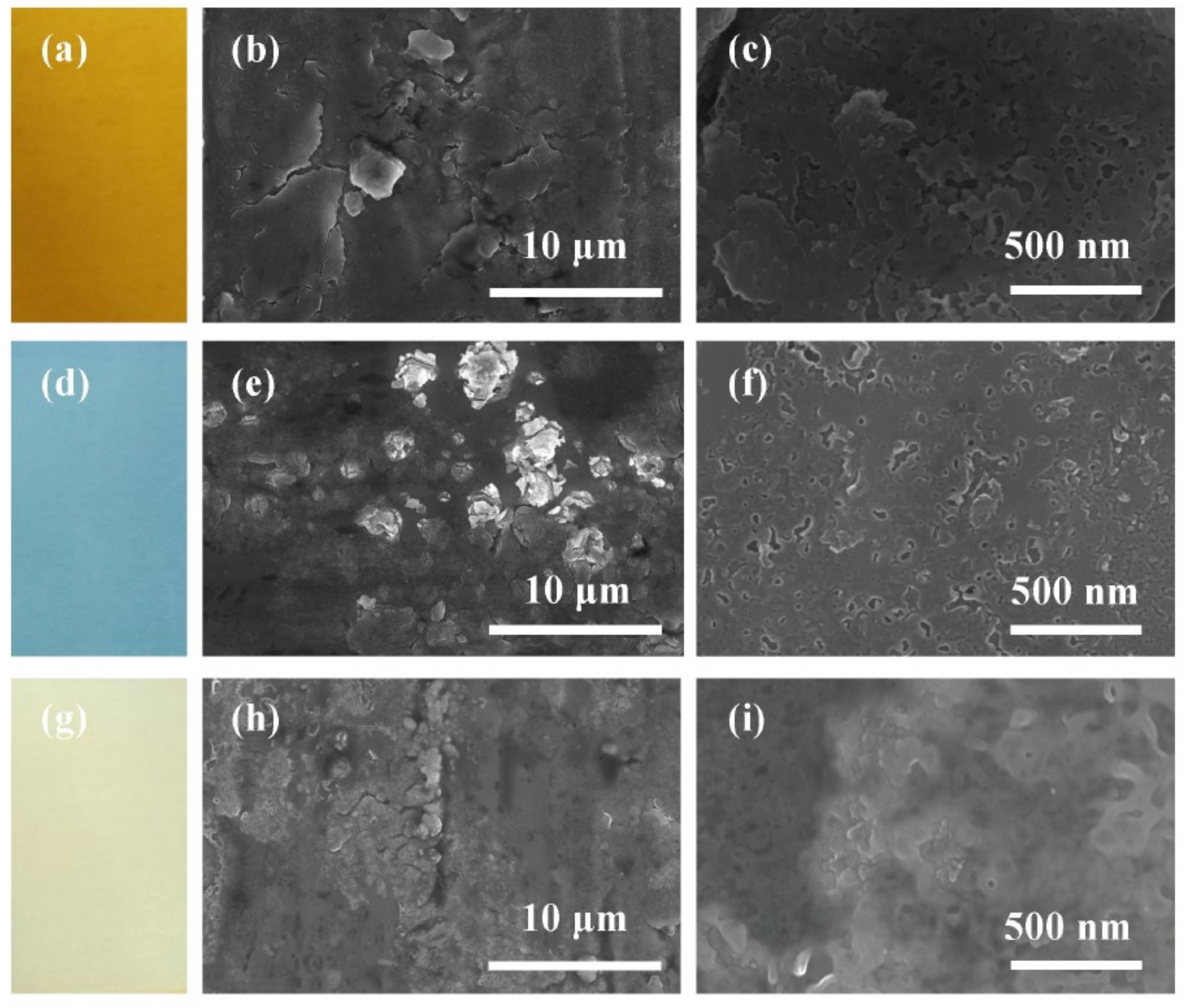
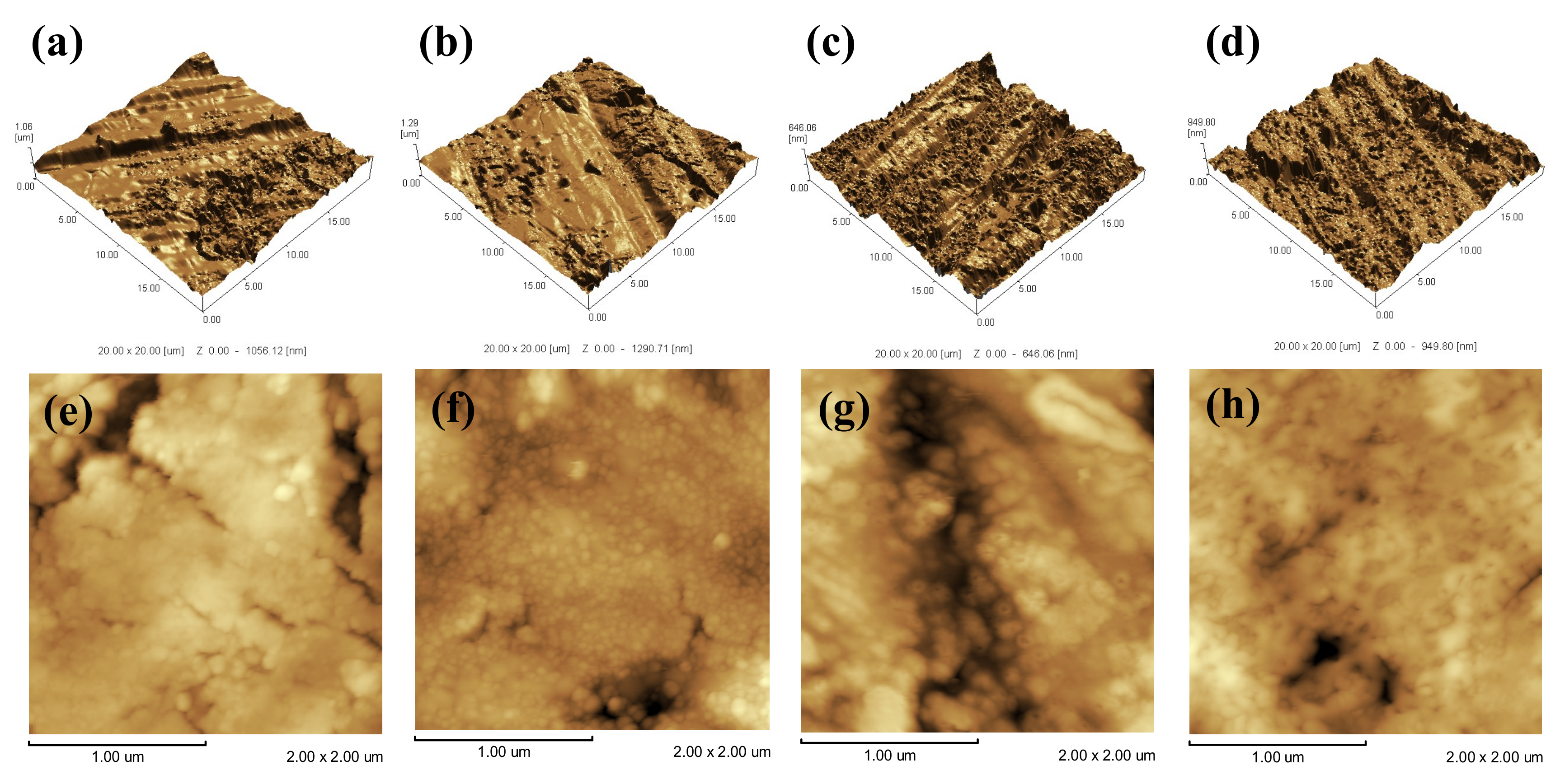
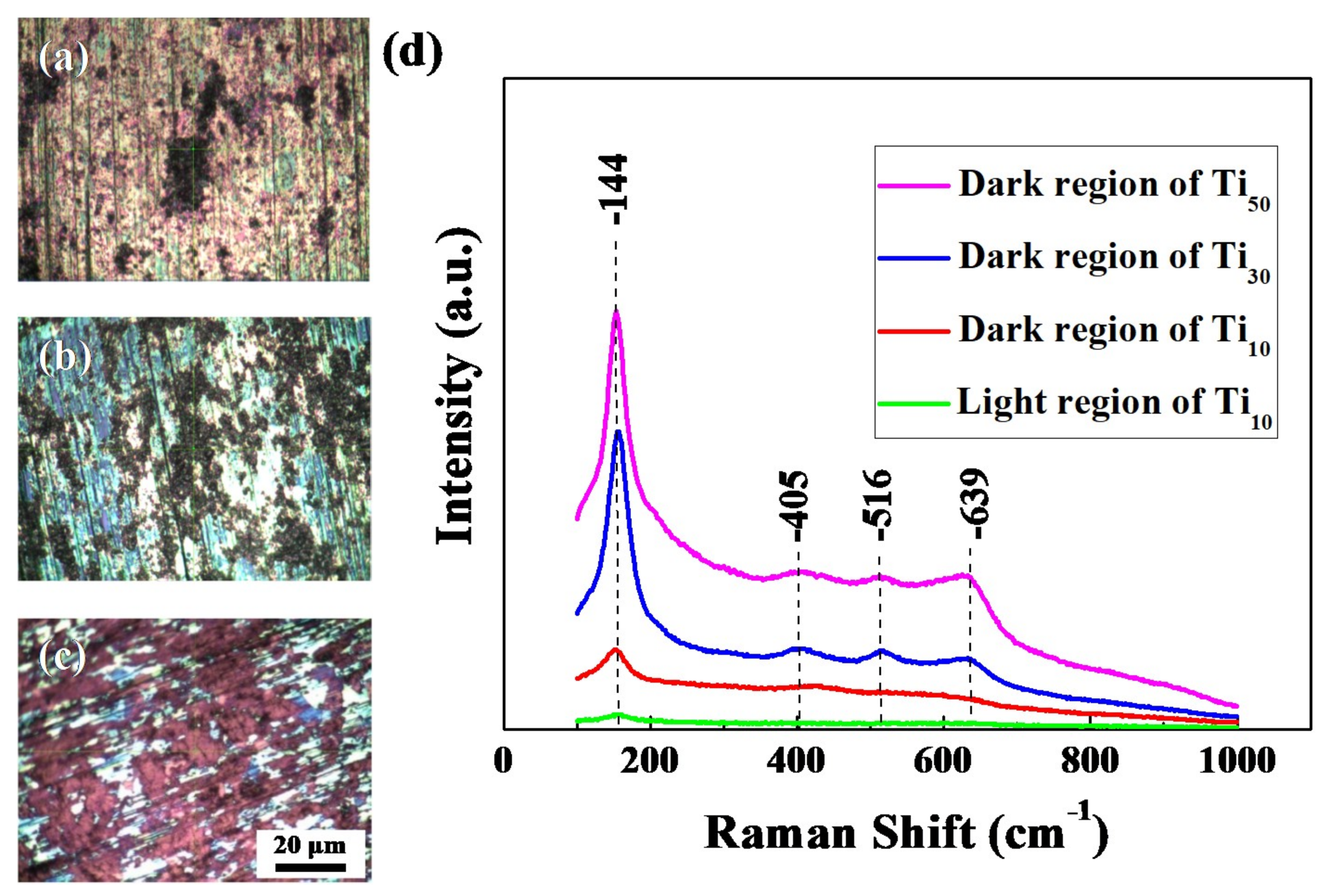
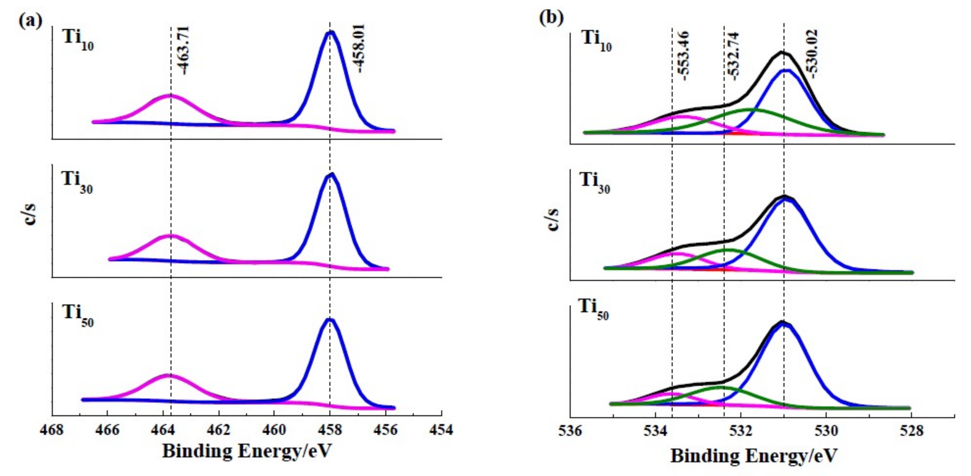
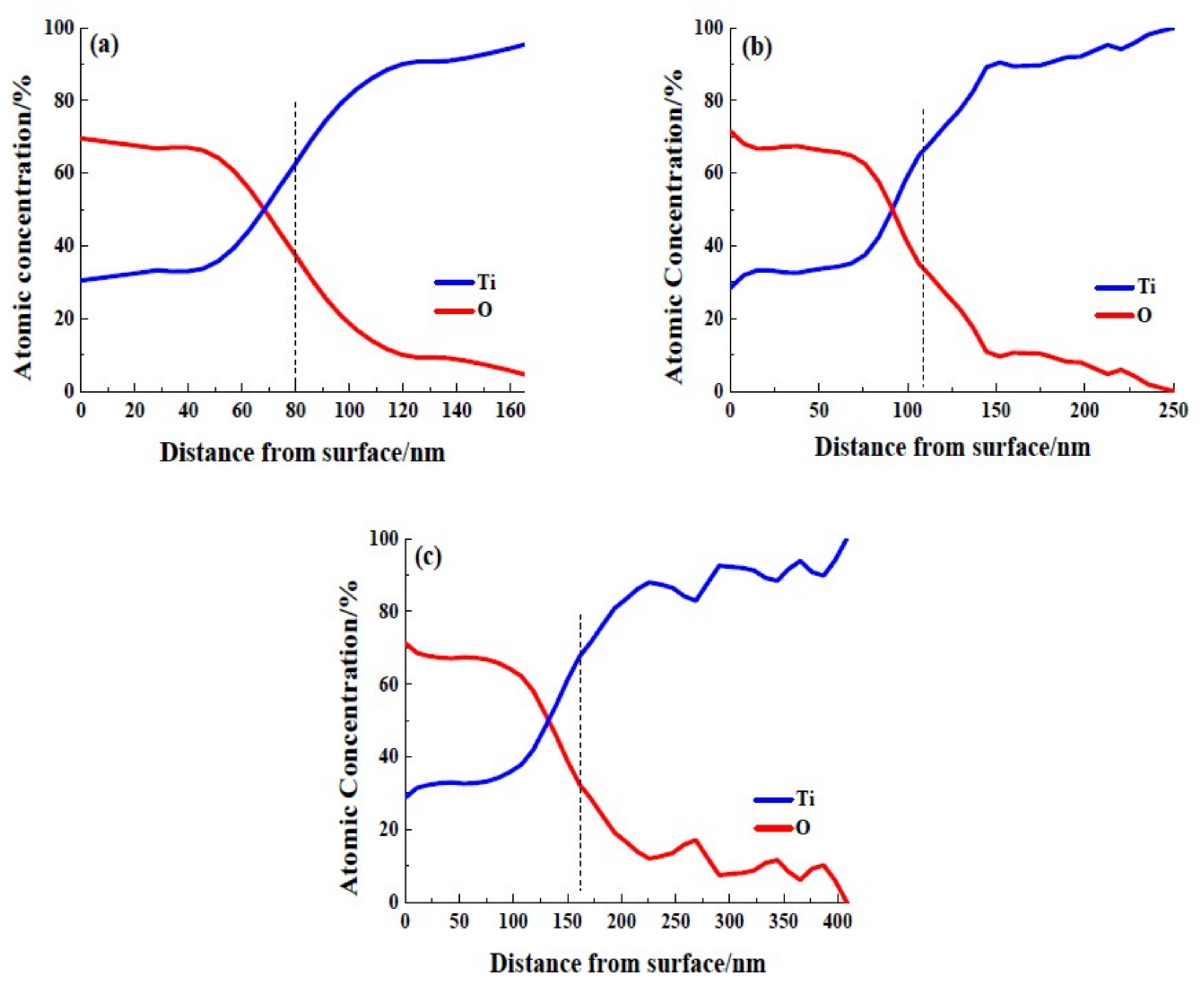
3.1. Surface Properties

Figure 1 shows photos and the SEM images of CP-Ti, Ti10, Ti30, and Ti50 samples. As shown in Figure 1a, the color of the oxide film formed on bare material is relatively dark grey. From Figure 1b,c, it can be seen that the film of bare material has lots of holes and scratches. As shown in Figure 1d,g,j, the sample surface changed into different colors after treated by anodic oxide treatment. It is well-known that titanium and its alloy exhibit various colors because of thin film interference of oxide films [22]. As the anodic voltages increase, the colors of the oxide film change from yellowish orange to grey, which shows that the higher the anodic voltage, the thicker the oxide film produced.
From Figure 1b,c, it can be observed that many cracks and nanopores appear on the Ti10 surface. As shown in Figure 1e,f, the passive film formed on Ti30 is relatively dense, some of the nanopores are slightly smaller. Some “flower-like” structures emerge. This is in accordance with the results of the other research [23]. According to the literature [17,24], these “flower-like” structures are mainly composed of crystalline grains, and are mostly attributed to manifestation of the dielectric breakdown of the film. When the anodic potential continued to increase, as shown in Figure 1h,i, the “flower-like” structures grow intensively and spread, covering the film surface and the passive film becomes flat and dense.
Figure 2 presents the AFM images of passive films produced under different anodic potential. Since the surface roughness parameter has an effect on the adhesion, adsorption and differentiation of Cl [25], it is also an important parameter affecting corrosion resistance [25]. The roughness parameter is generally labeled with Ra, which represents the arithmetic mean of the deviation of the rough contour from the average line profile measured over the entire length [26]. The roughness measured by AFM of bare material is 121.627 nm, as shown in Figure 2a. Ra of the Ti10 is calculated to be about 106.566 nm corresponding to 3D profile as shown in Figure 2b. The Ti30 revealed a surface roughness Ra equal to 84.098 nm (Figure 2c), while Ti50 is quite smooth with a lower surface roughness Ra = 43.094 nm (Figure 2d).
Furthermore, no nanocrystalline grains can be found on the surface of CP-Ti (Figure 2e). As shown in Figure 2f, lots of nanocrystalline grains with similar shape and dimension (around 50 nm) can be observed on the surface of Ti10. In the case of 30 V, the randomly distributed nanoscale grains grow larger (Figure 2g). For Ti50, the TiO2 nanocrystalline grains join together and form a smooth region (Figure 2h). In summary, when the commercially pure titanium was treated at a higher potential at the potentiodynamic-aging mode, the growth of the oxide film is favored, decreasing its roughness, and increasing its flatness.
The crystallization of the obtained passive films was evaluated by Raman spectrum. Figure 3 shows the optical microscopy photos and Raman spectrum of passive film formed on Ti10, Ti30, and Ti50. The optical microscopy photos under different anodic potentials are shown in Figure 3a–c. The images of all samples have two distinguishable regions, the dark, and the light region, which means that the crystallization of the passive film is non-uniform. This phenomenon is in accordance with the results of Raman spectrum.
The Raman bands at around 144, 405, 516 and 639 cm−1 are in accordance with the values of the Eg, B1g, A1g or B1g and Eg modes of anatase phase, respectively. Furthermore, the Raman band at about 144 cm−1 is the long range order of anatase phase, Raman bands at about 405, 516 and 639 cm−1 are the short range ones [27]. When the Raman microlaser beam is centered respectively on the dark and the light region of anodic oxide film grown on the Ti10, the results are shown in the spectrum red and green in Figure 3d. It is clear that a low-frequency Eg mode is observed in the dark region, while no Raman band can be found in the light region. The Raman band is weak and has an obvious shift towards lower wave number, which indicates that the passive film formed on Ti10 in dark region is composed of nanometer-scale anatase phase [28]. This phenomenon clearly implies that the dark region is more crystalline than the light region. On the Ti30 samples, the dark regions Raman spectra were composed of a strong band about 144 cm−1 and three weak bands about 405, 516, 639 cm−1, which are attributed to long range order and short range order of anatase phase. Additionally, when the anode voltage increased to 50 V, the Raman peaks become sharper and stronger. According to Xing et al. [23], the Raman band intensity is proportional to the film crystallinity. These results clearly show that the crystallization of passive films is enhanced by increasing the anodic potential at the potentiodynamic-aging mode.
The surface chemical state of the anodic oxide films formed at different anodic potentials was characterized via XPS analysis. As Figure 4 shows, the resulting wide-range XPS spectrum of each specimen indicates that Ti, O and C elements in the passive film. The C 1s peak, which occurs at 284.06 eV, is attributed to the surface-contaminant hydrocarbon layer that covers the topmost surface of the samples [29].
XPS measurements were used to characterize the chemical state of passive film formed on specimens and the results are illustrated in Figure 4. By using the results from Wang et al. [30] and Jiang et al. [31], we determined the possible species in anodic oxide films, as shown in Table 1.
After deconvolution using Gaussian-Lorentzian functions, Ti 2p3/2 narrow-scan spectrums of the specimens, reveal a major peak at 458.01 eV corresponding to Ti4+ species, as shown in Figure 5a. The O 1s narrow-scan spectrums, as shown in Figure 5b, are composed of three peaks, which correspond to O2−, OH, and adsorbed water. The O2− is reported to assign to oxygen atoms in TiO2, and the OH and the adsorbed water may be from the hydrated titanium oxides. This phenomenon has been reported in other research [23,32]. The Ti 2p narrow-scan spectrum of all samples indicate that anodic oxidation treatment favors the transformation from lower valence states to Ti4+, and enhancing thermodynamically stability of the anodic oxide film. In addition these peaks reveal the outmost surface (0 nm) of all samples consist of TiO2, Ti(OH)4 and TiO2·nH2O.
The anodic potential effect on the percentage contents of O2−, OH and adsorbed water of the anodic oxide film are summarized in Table 2. Compared the contribution of O 1s components in Ti10, Ti30, and Ti50 samples, it indicates that the O2− increases and the OH, H2O decrease with increasing anodic potential. As mentioned by other research [17], the hydroxide group and adsorbed water were unfavorable for the crystallization. This result indicates that enhancing the anodic voltage has a positive effect on the formation of dehydrated and TiO2 dominated anodic oxide film, which is in accordance with the results of Roman spectrum.
In order to compare the thickness of the passive film formed on different anodic potentials, XPS depth profiles were carried out. Figure 6 depicts Ti and O atomic percentages varying with sputtering depth of each sample. The thickness of the anodic oxide films can be calculated by the XPS depth profiles at the point where the oxygen-atoms concentration dropped to 50% of its maximum value [33,34], in which case the value is calculated to be about 35%. Figure 6a shows that the thickness of anodic oxide film formed on 10 V is about 80 nm. Figure 6b reveals that the thickness of the anodic oxide film formed on 30 V is about 114 nm. Whereas, the thickness of the anodic oxide film formed on 50 V is about 160 nm (Figure 6c). The grown rate abstracted from Figure 6 was about 1.5 nm V−1, which is commonly found on other passivated metals [35].
The XPS narrow-scan spectrum spectra recorded from surface to depth of the anodic oxide films exhibited the chemical state of Ti 2p and O 1s peaks, as shown in Figure 7a,c,f and Figure 7b,d,e respectively. For Ti10 sample (as shown in Figure 7a,b), the Ti2p spectra in a depth of 34 nm show the presence of Ti2+. Furthermore, O element existed in the form of O2−, OH. These results reveal the anodic oxide film is consisted of TiO2, Ti(OH)4, and TiO in the depth from 0 to 34 nm. In the sputtering depth from 34 to 72 nm, Ti3+ and metallic Ti0 occurred, and the peak intensity from Ti2+ weakened. The XPS data suggest that the anodic oxide film in this region mainly consists of Ti2O3, TiO, and metallic Ti0. In a depth of 120 nm, the peaks attributed to Ti3+ and Ti2+ disappeared and the peak attributed to metallic Ti0 became higher. For Ti30 sample (as shown in Figure 7c,d), the Ti 2p spectra recorded at 52 nm is assigned to Ti4+ and Ti2+. The O 1s spectra recorded in the depth of 52 nm is composed of O2− and OH. The XPS data indicate that chemical compositions of the anodic oxide film are TiO2, TiO, and Ti(OH)4 in the depth of 0–52 nm. In the depth of 75 nm, the peaks attributed to Ti4+ weakened and the peaks due to Ti2+ became higher. In the depth from 75 to 143 nm, the anodic oxide film is composed of Ti2O3, TiO, and metallic Ti. In the depth of 196 nm, both Ti2O3 and TiO disappeared and only the metallic Ti0 is observed. For Ti50 sample (as shown in Figure 7e,f), the Ti 2p spectra recorded at 75 nm is composed of Ti4+ and Ti3+. The O element in this depth is O2− and OH. The XPS results reveal that the components in the anodic oxide film are TiO2, Ti2O3, and Ti(OH)4 in the depth from 0 to 75 nm. In the depth from 75 to 124 nm, the anodic oxide film is composed of TiO2, TiO, and Ti(OH)4. In the depth of 124–175 nm, the anodic oxide film is composed of TiO2, Ti2O3, Ti(OH)4 and metallic Ti0. In the depth of 175–196 nm, the major constituents of the film are TiO and metallic Ti0. In the depth of 232 nm, only the metallic Ti0 can be detected. In addition, metallic Ti0 can be found throughout the anodic oxide film and mainly exist near the substrate in each sample.
The XPS results also show that the anodic oxide film are mainly composed of TiO2, Ti2O3, TiO, metallic Ti0, Ti(OH)4, and TiO2.H2O. Therefore, the XPS analysis provides many extra pieces of evidence to support the discussions of SEM and Raman spectrum to clarify the relationship between compositions of anodic oxide films and anodic potentials.

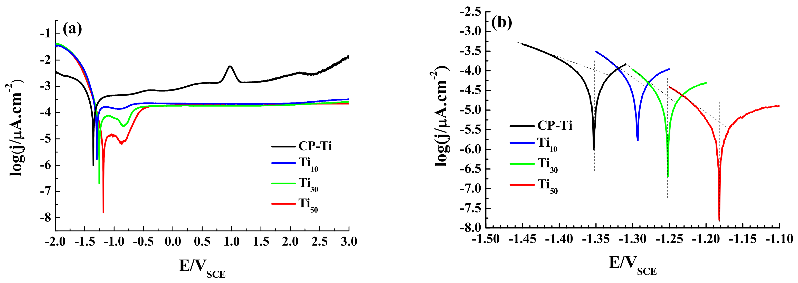
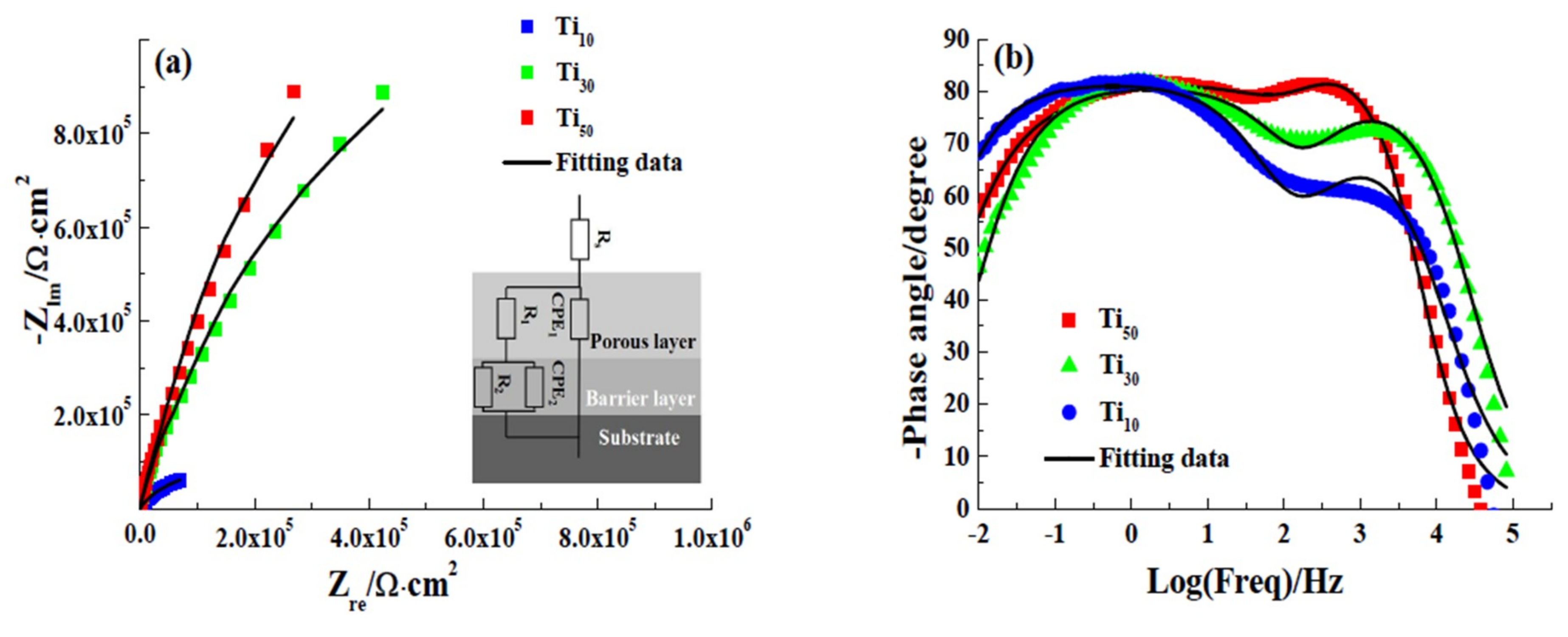
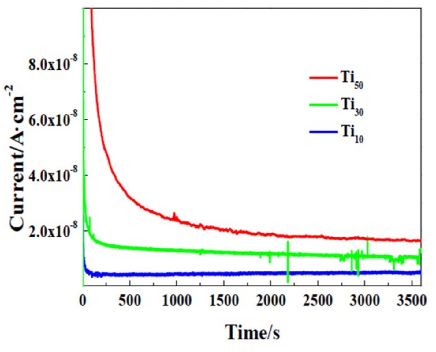
3.2. Electrochemical Tests

Figure 8 shows potentiodynamic polarization curves measured in 3.5 wt.% NaCl solution. In the present case, the cathodic reduction reaction is oxygen absorption reaction [36]. The chemical equation may be:
O 2 + 2 H 2 O + 4 e 4 O H
The corrosion potential (Ecorr) and corrosion current density (jcorr) were obtained from the Figure 8 by Tafel extrapolation and summarized in Table 3 [37]. In order to obtain the accurate extrapolation results, anodic or cathodic branch should exhibit Tafel behavior. In addition, the extrapolation should be used at least 50 to 100 mV away from Ecorr [38]. As Ti and its alloy do not have Tafel behavior in anodic branch [39], only the cathodic Tafel line was used to extrapolate to the Ecorr to determine the jcorr in this study. Ecorr, values of –1.352, –1.297, –1.252 and –1.181 VSCE, and jcorr, values of 1.258 × 10⁻⁴, 5.623 × 10⁻⁵, 1.995 × 10⁻⁵, and 5.623 × 10⁻⁶ μA·cm−2 were obtained for the CP-Ti, Ti10, Ti30, and Ti50, respectively. The higher Ecorr and the lower jcorr means the lower susceptibility to corrosion [40]. The results indicate that the anodic oxidation treatment has a positive effect of improving the corrosion resistance of CP-Ti. Furthermore, as the anodic potential increases, the Ecorr increases and jcorr decreases. This is a clear indication that the anodic potential has a positive effect on the corrosion resistance of CP-Ti.
Electrochemical impedance spectroscopy (EIS) was used to obtain important parameters associated with the anodic oxide film, such as the charge transfer resistance, capacitance and thickness of the anodic oxide film [41]. It can be seen that Nyquist plots were characterized by flattened and incomplete semi-circles in the entire frequency range, as shown in Figure 9a. This semi-circle is associated with the charge transfer reaction occurring at the metal/electrolyte interface. The larger the diameter of the arc is, the greater the electron transfer resistance is, and the stronger the stability of the oxide film is [42]. The semi-circle increases with increasing anodic potential, which means that the anodic potential has greatly improved the corrosion resistance of CP-Ti. The Nyquist plot of the Ti50 is almost a straight line which indicates good insulating properties of the anodic oxide film.
Furthermore, two time constants are well distinguished in the Bode plot. According to Robin [43], the anodic oxide film formed on Ti and its alloy is a double layer structure which consists of a porous outer layer and a barrier inner layer. The EIS were fitted using an electrical equivalent circuit (EEC), in which two time constants was chosen to represent the double layer structure. In this EEC, RS is the solution resistance, R1 and R2 are the charge transfer resistances of the porous layer and barrier layer. The symbol Q corresponding to a constant phase element (CPE) with varying α, stands for the possibility of a non-ideal capacitance behavior. The symbol Q corresponding to a constant phase element (CPE) with varying α, stands for the possibility of a non-ideal capacitance behavior. Q1 and Q2 are the CPE of the porous outer layer and barrier inner layer. The mathematical formulation of CPE can be obtained by Equation (2) [44]:
Z CPE ( ω ) = 1 Q ( j w ) α
where Q is the magnitude of the CPE in F·cm−2 sα−1, ω is the angular frequency (ω = 2πf) in rad·s−1, f is the frequency in Hz, j is the imaginary number ( j = 1 ), α is the CPE exponent which is adjusted between 0 and 1. For α = 1, the CPE represents an ideal capacitor; for α = 0, the CPE represents an ideal resistor; for α = 0.5, the CPE behaves a Warburg impedance with diffusion character, for 0.5 < α < 1, the CPE describes a distribution of dielectric relaxation times in the frequency domain [25,45]. The value of α is related to surface state [46].
Table 4 shows the fitted results of the impedance spectra. The Chi-squared (χ2) values were lower than 10−3 which indicates satisfactory agreement between the experimental and fitting data. Rs remains almost constant in all tests. R1 increases from 1.79 Ω·cm−2 for the Ti10 to 43.78 Ω·cm−2 for the Ti30 and further to 89.45 Ω·cm−2 for the Ti50, respectively. R1 was increased by two orders of magnitude through enhancing the anodic potential. Additionally, R2 of the Ti10, Ti30 and Ti50 are about 489.53, 502.56, and 512.48 Ω·cm−2, respectively. It is clear that the values of R2 are higher than the R1 values, indicating that the inner layer is a more compact film than the outer layer. However, R2 increase slowly with the increment of anodic potential, which reflects that the increase of potential has little effect on the inner layer. The value of R1 depends strongly on the existence of pores, channels or cracks which the solution can penetrate [47]. Combined the results of SEM, Raman spectrum, XPS, it is revealed that the surface roughness is decreased, the density and the crystallinity is increased, and the resistance of the outer porous layer significantly improved with increasing the potential.
Furthermore, the value of Q decreases with increasing applied potential. The increase of transfer charge resistances and the decreased value of Q indicated continuous growth of the anodic oxide film with the increment of potential value.
The CPE used in EEC has been converted into a pure capacitance (C) via Equation (3) [48]:
C = ( Q R ) 1 α R
where R is the film resistance, Q is the magnitude of the CPE, α is the CPE exponent. The values of C1 of Ti10, Ti30, and Ti50 are 0.08121, 0.02611, and 0.02078 μF cm−2, respectively. C2 decreases from 0.08935 Ω·cm−2 for the Ti10 to 0.05964 Ω·cm−2 for the Ti30 and further to 0.04896 Ω·cm−2 for the Ti50, respectively. It can be seen that both C1 and C2 values decrease with the increment of potential value insulating the growth of the anodic oxide film. The thickness of the anodic oxide film can be calculated using Equation (4):
L = ε ε 0 C
where ε is the relative dielectric constant of the film, ε0 is the dielectric constant in vacuum (8.8542 × 10⁻¹⁴ F·cm−1) and L denotes the film thickness. As the Raman results show that crystalline form of the film is anatase, the ε of porous outer layer can be considered as 48 [49]. Based on the XPS results, the chemical condition of barrier inner layer is amorphous titanium oxide, hence the value of ε is taken as 33 [50]. Thickness of the barrier inner layer and porous outer layer of anodic oxide films formed at different potentials are shown in Table 5, it is clear that the porous outer layer thickness is larger than the barrier inner layer. Moreover, the potential has a greater influence on the thickness of the outer porous layer.
The EIS results demonstrate that increasing anodic potential positive affects the protective properties of the anodic oxide films formed on CP-Ti. Increasing the potential can increase the thickness of the anodic oxide film and the charge transfer resistance, and the effect on the outer layer is more obvious.

3.3. Discussion

I–t curves of CP-Ti under potentiodynamic-aging mode at 10, 30 and 50 V are shown in Figure 10. It can be seen from the curves that the current density is very large at the first stage. Subsequently, the current density decreases dramatically during the first few seconds. Finally it remains at steady state until the end of the anodic treatment. It can be indicated that the oxide film has been formed in only a few seconds and the current fluctuations may be related to the oxygen evolution reaction (OER) [51]. Moreover, it can be also found that after the initial drop, the steady state current density is much larger for CP-Ti anodization at higher anodic potential. Additionally, the larger current density at higher anodic potential means that the film growth is higher [52].
Based on the results mentioned above, the growth and crystallization process of passive films under potentiodynamic-aging mode are shown in Figure 11 and Figure 12. According to our previous studies [53], the oxide film of titanium is an n-type semiconductors, which indicates the defects in the oxide film are donors, such as oxygen vacancies and titanium interstitials [54]. The formation energy of oxygen vacancies and titanium interstitials is 2.7 and 4.7 eV, respectively [55]. Therefore, oxygen vacancies are considered to be dominant donors. However, titanium interstitials is also under consideration in the present study.
These point defects transport through the oxide film and undergo defect reactions at the Ti/oxide film (Ti/f) and film/solution (f/s) interfaces. According to Veluchamy et al. [56], the transport and reaction of these point defects determine the growth of the oxide film. The point defect model (PDM) was used to describe the growth process of oxide films on Ti surfaces and can be schematically illustrated in Figure 10 and R1–R8 (Figure 11).
The equations are expressed in Kröger-Vink notation [57], where the VTi represents Ti vacancy, VTi’’’’ repesents Ti cation vacancy, VO•• represents O vacancy, TiTi represents Ti in Ti site on the cation sublattice, Tii•••• represents Ti cation interstitial, OO represents oxide ion in oxide site on the anion sublattice, Ti4+(aq) represents Ti4+ in solution, Ti(H2O)n4+ repesents Ti and hydrated titanium complexes, respectively. The electrical field of the oxide film enables the defects through the film at room temperature [57,58].
R1–R3 happen at the Ti/inner layer interface. R1 expresses the submergence of cation vacancies, VTi’’’’ into the Ti lattice. It results in the formation of TiTi in the oxide lattice and a vacancy VTi into the Ti lattice. R2 represents Ti reacting with VTi which generates TiTi and VO••. It results in the movement of the Ti/f toward the Ti side. R3 corresponds to metal Ti generating VTi’’’’ and VTi. R5–R8 take place at the outer layer film/solution interface (f|s). R5 represents the formation of VTi’’’’ and Ti(H2O)n4+, which are soluble. VTi’’’’ is transferred by the electric field toward the Ti|f where they are annihilated towards the Ti side (R1). R6 indicates the absorption of O2− into VO•• resulting in OO. R7 represents the dissolution of the oxide film. In addition, the dissolution of the oxide film is necessary for the oxide film to attain steady-state. Cation-vacancy annihilation (via R4) leads to VO••/VTi’’’’ interactions, which are driven by the electrostatic attraction between high concentrations of oppositely charged defects [59]. R9 corresponds to the oxygen evolution reaction.
The addition of R1 and R5 or R2 and R6 result in the Tii•••• and VTi’’’’ eliminated, yields:
Ti Ti 4 + ( a q ) + v Ti + 4 e
which indicates metal Ti dissolution. The barrier inner layer is a semi-permeable membrane [54]. The addition of R3 and R8, result in the oxygen vacancy eliminated, yields:
Ti + χ H 2 O T i T i + χ O O + e
which corresponds to the growth of the barrier layer. VO•• generated at f/s via R2 and annihilated at Ti/f via R6. By means of hopping mechanism, the OO ions are transferred through VO•• toward the Ti/f. Meanwhile, VO•• is transferred towards the f/s via the electric field and the concentration gradient [54], which determines barrier layer growth towards into the metal. The species in the solution does not participate in the growth of the barrier layer. This result is in accordance with the XPS results that the barrier layer contains only Ti and O elements. The outer layer forms by the hydrolysis of H2O. As a result, the outer layer comprises oxide, hydroxide and hydrated oxide. The growth rate of the anodic oxide film is related to the concentration of oxygen vacancies which depends on applied potential [3]. Therefore, the higher the anodic potential, the thicker film oxide film thickness.
The crystallization stage of anodic titanium oxide films under different potentials are shown in Figure 11. As mentioned by other research [60,61], the crystallization of the of anodic oxide film is considered to be a thermally-induced, slow evolving process, and promoted by enhancing the oxide potential.
For Ti10 sample, at the end of grown stage, the current density is relatively small, the film crystallization occurs at a very slow speed, numerous micro-crystals randomly emerge at the beginning of titanium anodization and grow to small crystalline grains in the following process. For the Ti30 sample, the current density is relatively large, the oxygen bubbles are formed and released from the surface due to the OER, and the films breakdown is enhanced. As reported by Dyer et al. [62], crystallization is promoted by breakdown of amorphous anodic oxide films because the breakdown can enhance the local current density. As a result, numerous of TiO2 micro-crystals grow quickly, and form bigger crystalline grains. When the titanium treated at 50 V, at the end of the grown stage, the current density is very large and the OER is very high frequency. Therefore, the micro-crystals are quickly formed. With the anodizing time prolonged, these micro-crystals join together and form a smooth region.

4. Conclusions

The effect of anodic potential on passive films in 0.5 M H2SO4 solution has been investigated using SEM, AFM, XPS, potentiodynamic polarization curves and EIS.
The SEM and AFM results show that the anodic potential has a positive effect on the characteristics of the passive film. With increasing anodic potential, the surface micromorphology became more compact and lower roughness. XPS analysis revealed that the thickness of the anodic oxide film increases with increasing anodic potential. The potentiodynamic polarization curves revealed that the Ecorr shifted towards more positive values and corrosion current density jcorr values decreased with increasing anodic potential.

Author Contributions

Conceptualization, L.Z. and T.F.; methodology, Y.D.; software, R.G.; validation, D.T.; formal analysis, L.Z.; investigation, T.F.; resources, L.Z.; data curation, K.W.; writing—original draft preparation, L.Z.; writing—review and editing, T.F.; visualization, D.T.; supervision, J.Y.; project administration, L.Z. and R.G.; funding acquisition, L.Z.

Funding

Science and Technology Project of Yunnan Province (Preparation and application of plateau characteristic plants based semicarbonized functional materials and fragrance); Foundational Project of China Tabacco Yunnan Industrial Co., Ltd. (2015CP02, 2015CP03); Technological Innovation Talent Project of Yunnan Province (2016HB009).

Conflicts of Interest

The authors declare no conflict of interest.

References

  1. Diamanti, M.V.; Pedeferri, M.P. Effect of anodic oxidation parameters on the titanium oxides formation. Corros. Sci. 2007, 49, 939–948. [Google Scholar] [CrossRef]
  2. Oliveira, V.M.C.A.; Aguiar, C.; Vazquez, A.M.; Robin, A.; Barboza, M.J.R. Improving corrosion resistance of Ti–6Al–4V alloy through plasma-assisted PVD deposited nitride coatings. Corros. Sci. 2014, 88, 317–327. [Google Scholar] [CrossRef]
  3. Jiang, Z.; Dai, X.; Norby, T.; Middleton, H. Investigation of pitting resistance of titanium based on a modified point defect model. Corros. Sci. 2011, 53, 815–821. [Google Scholar] [CrossRef]
  4. Li, S.; Yao, W.; Liu, J.; Yu, M.; Wu, L.; Ma, K. Study on anodic oxidation process and property of composite film formed on Ti–10V–2Fe–3Al alloy in SiC nanoparticle suspension. Surf. Coat. Technol. 2015, 277, 234–241. [Google Scholar] [CrossRef]
  5. Hanawa, T. Metal ion release from metal implants. Mater. Sci. Eng. C 2004, 24, 745–752. [Google Scholar] [CrossRef]
  6. Jiang, Z.; Norby, T.; Middleton, H. Evaluation of metastable pitting on titanium by charge integration of current transients. Corros. Sci. 2010, 52, 3158–3161. [Google Scholar] [CrossRef]
  7. Manhabosco, T.M.; Tamborim, S.M.; Santos, C.B.D.; Müller, I.L. Tribological, electrochemical and tribo-electrochemical characterization of bare and nitrided Ti6Al4V in simulated body fluid solution. Corros. Sci. 2011, 53, 1786–1793. [Google Scholar] [CrossRef]
  8. Wang, J.; Ma, Y.; Guan, J.; Zhang, D. Characterizations of anodic oxide films formed on Ti6Al4V in the silicate electrolyte with sodium polyacrylate as an additive. Surf. Coat. Technol. 2018, 338, 14–21. [Google Scholar] [CrossRef]
  9. Narayanan, R.; Seshadri, S.K. Phosphoric acid anodization of Ti–6Al–4V—Structural and corrosion aspects. Corros. Sci. 2007, 49, 542–558. [Google Scholar] [CrossRef]
  10. Karambakhsh, A.; Afshar, A.; Ghahramani, S.; Malekinejad, P. Pure Commercial Titanium Color Anodizing and Corrosion Resistance. J. Mater. Eng. Perform. 2011, 20, 1690–1696. [Google Scholar] [CrossRef]
  11. Simka, W.; Sadkowski, A.; Warczak, M.; Iwaniak, A.; Dercz, G.; Michalska, J.; Maciej, A. Characterization of passive films formed on titanium during anodic oxidation. Electrochim. Acta 2011, 56, 8962–8968. [Google Scholar] [CrossRef]
  12. Xing, J.H.; Xia, Z.B.; Hui, L.I.; Wang, Y.Y.; Zhong, L. Growth and crystallization behaviors of anodic oxide films on sputter-deposited titanium at very low potentials. Trans. Nonferrous Met. Soc. China 2013, 23, 3286–3292. [Google Scholar] [CrossRef]
  13. Kuromoto, N.K.; Simão, R.A.; Soares, G.A. Titanium oxide films produced on commercially pure titanium by anodic oxidation with different voltages. Mater. Charact. 2007, 58, 114–121. [Google Scholar] [CrossRef]
  14. Nanjo, H.; Deng, H.; Oconer, I.S.; Ishikawa, I.; Suzuki, T.M. Effect of Ultraviolet Light Irradiation on Structure and Electrochemical Properties of Iron Surface. Jpn. J. Appl. Phys. 2005, 44, 539–542. [Google Scholar] [CrossRef]
  15. Sivakumar, B.; Pathak, L.C.; Singh, R. Role of surface roughness on corrosion and fretting corrosion behaviour of commercially pure titanium in Ringer’s solution for bio-implant application. Appl. Surf. Sci. 2017, 401, 385–398. [Google Scholar] [CrossRef]
  16. Xia, Z.; Nanjo, H.; Aizawa, T.; Kanakubo, M.; Fujimura, M.; Onagawa, J. Growth process of atomically flat anodic films on titanium under potentiostatical electrochemical treatment in H2SO4 solution. Surf. Sci. 2007, 601, 5133–5141. [Google Scholar] [CrossRef]
  17. Xing, J.H.; Xia, Z.B.; Hu, J.F.; Zhang, Y.H.; Zhong, L. Growth and Crystallization of Titanium Oxide Films at Different Anodization Modes. J. Electrochem. Soc. 2013, 160, C239–C246. [Google Scholar] [CrossRef]
  18. Delplancke, J.L.; Garnier, A.; Massiani, Y.; Winand, R. Influence of the anodizing procedure on the structure and the properties of titanium oxide films and its effect on copper nucleation. J. Appl. Polym. Sci. 1994, 39, 1281–1289. [Google Scholar] [CrossRef]
  19. Kudelka, S.; Michaelis, A.; Schultze, J.W. Effect of texture and formation rate on ionic and electronic properties of passive layers on Ti single crystals. Electrochim. Acta 1996, 41, 863–870. [Google Scholar] [CrossRef]
  20. Alves, A.; Wenger, F.; Ponthiaux, P.; Celis, J.-P.; Pinto, A.; Rocha, L.; Fernandes, J. Corrosion mechanisms in titanium oxide-based films produced by anodic treatment. Electrochim. Acta 2017, 234, 16–27. [Google Scholar] [CrossRef]
  21. Mu, S.; Li, N.; Li, D.; Zou, Z. Investigation of a transparent chromate (III) passive film on electroless Ni–P coating by XPS and electrochemical methods. Electrochim. Acta 2009, 54, 6718–6724. [Google Scholar] [CrossRef]
  22. Komatsu, I.; Aoki, H.; Ebisawa, M.; Kuroda, A.; Kuroda, K.; Maeda, S. Color change mechanism of niobium oxide thin film with incidental light angle and applied voltage. Thin Solid Film. 2016, 603, 180–186. [Google Scholar] [CrossRef]
  23. Xing, J.; Xia, Z.; Hu, J.; Zhang, Y.; Zhong, L. Time dependence of growth and crystallization of anodic titanium oxide films in potentiostatic mode. Corros. Sci. 2013, 75, 212–219. [Google Scholar] [CrossRef]
  24. Matykina, E.; Arrabal, R.; Skeldon, P.; Thompson, G.E.; Habazaki, H. Influence of grain orientation on oxygen generation in anodic titania. Thin Solid Film. 2008, 516, 2296–2305. [Google Scholar] [CrossRef]
  25. Benea, L.; Danaila, E.; Ponthiaux, P. Effect of titania anodic formation and hydroxyapatite electrodeposition on electrochemical behaviour of Ti–6Al–4V alloy under fretting conditions for biomedical applications. Corros. Sci. 2015, 91, 262–271. [Google Scholar] [CrossRef]
  26. Elias, C.N.; Oshida, Y.; Lima, J.H.C.; Muller, C.A. Relationship between surface properties (roughness, wettability and morphology) of titanium and dental implant removal torque. J. Mech. Behav. Biomed. Mater. 2008, 1, 234. [Google Scholar] [CrossRef] [PubMed]
  27. Ohtsuka, T.; Guo, J.; Sato, N. ChemInform Abstract: Raman Spectra of the Anodic Oxide Film on Titanium in Acidic Sulfate and Neutral Phosphate Solutions. Cheminform 1987, 18, 2473–2476. [Google Scholar] [CrossRef]
  28. Si, H.Y.; Sun, Z.H.; Kang, X.; Zi, W.W.; Zhang, H.L. Voltage-dependent morphology, wettability and photocurrent response of anodic porous titanium dioxide films. Microporous Mesoporous Mater. 2009, 119, 75–81. [Google Scholar] [CrossRef]
  29. Fattah-Alhosseini, A. Passivity of AISI 321 stainless steel in 0.5 M H2SO4 solution studied by Mott–Schottky analysis in conjunction with the point defect model. Arab. J. Chem. 2016, 9, S1342–S1348. [Google Scholar] [CrossRef]
  30. Wang, C.; Pan, L.; Zhang, Y.; Xiao, S.; Chen, Y. Deoxidization mechanism of hydrogen in TiH2 dehydrogenation process. Int. J. Hydrogen Energy 2016, 41, 14836–14841. [Google Scholar] [CrossRef]
  31. Jiang, Z.; Dai, X.; Middleton, H. Effect of silicon on corrosion resistance of Ti–Si alloys. Mater. Sci. Eng. B 2011, 176, 79–86. [Google Scholar] [CrossRef]
  32. Tsutsumi, Y.; Nishimura, D.; Doi, H.; Nomura, N.; Hanawa, T. Difference in surface reactions between titanium and zirconium in Hanks’ solution to elucidate mechanism of calcium phosphate formation on titanium using XPS and cathodic polarization. Mater. Sci. Eng. B 2009, 29, 1702–1708. [Google Scholar] [CrossRef]
  33. Vesel, A.; Mozetic, M.; Drenik, A.; Hauptman, N.; Balat-Pichelin, M. High temperature oxidation of stainless steel AISI316L in air plasma. Appl. Surf. Sci. 2008, 255, 1759–1765. [Google Scholar] [CrossRef]
  34. Gui, Y.; Meng, X.B.; Zheng, Z.J.; Gao, Y. Critical temperature determination of detectable Cr diffusion enhancement by nanostructure through structural evolution analysis of the oxide films at 25–450 °C on 304 stainless steel. Appl. Surf. Sci. 2017, 419, 512–521. [Google Scholar] [CrossRef]
  35. Kirchheim, R. Growth kinetics of passive films. Electrochim. Acta 1987, 32, 1619–1629. [Google Scholar] [CrossRef]
  36. Krawiec, H.; Vignal, V.; Schwarzenboeck, E.; Banas, J. Role of plastic deformation and microstructure in the micro-electrochemical behaviour of Ti–6Al–4V in sodium chloride solution. Electrochim. Acta 2013, 104, 400–406. [Google Scholar] [CrossRef]
  37. Mccafferty, E. Validation of corrosion rates measured by the Tafel extrapolation method. Corros. Sci. 2005, 47, 3202–3215. [Google Scholar] [CrossRef]
  38. Poorqasemi, E.; Abootalebi, O.; Peikari, M.; Haqdar, F. Investigating accuracy of the Tafel extrapolation method in HCl solutions. Corros. Sci. 2009, 51, 1043–1054. [Google Scholar] [CrossRef]
  39. Kelly, E.J. Electrochemical Behavior of Titanium; Springer: New York, NY, USA, 1982. [Google Scholar]
  40. Fu, T.; Zhan, Z.; Zhang, L.; Yang, Y.; Liu, Z.; Liu, J.; Li, L.; Yu, X. Effect of surface mechanical attrition treatment on corrosion resistance of commercial pure titanium. Surf. Coat. Technol. 2015, 280, 129–135. [Google Scholar] [CrossRef]
  41. Hernández-López, J.M.; Conde, A.; Damborenea, J.J.D.; Arenas, M.A. Electrochemical response of TiO2 anodic layers fabricated on Ti6A14V alloy with nanoporous, dual and nanotubular morphology. Corros. Sci. 2016, 112, 194–203. [Google Scholar] [CrossRef]
  42. Ningshen, S.; Mudali, U.K.; Ramya, S.; Raj, B. Corrosion behaviour of AISI type 304L stainless steel in nitric acid media containing oxidizing species. Corros. Sci. 2011, 53, 64–70. [Google Scholar] [CrossRef]
  43. Robin, A.; Meirelis, J.P. Influence of fluoride concentration and pH on corrosion behavior of Ti-6Al-4V and Ti-23Ta alloys in artificial saliva. Mater. Corros. 2015, 58, 173–180. [Google Scholar] [CrossRef]
  44. Ter-Ovanessian, B.; Alemany-Dumont, C.; Normand, B. Electronic and transport properties of passive films grown on different Ni-Cr binary alloys in relation to the pitting susceptibility. Electrochim. Acta 2014, 133, 373–381. [Google Scholar] [CrossRef]
  45. Xu, J.; Liu, L.; Li, Z.; Munroe, P.; Xie, Z.H. Niobium addition enhancing the corrosion resistance of nanocrystalline Ti5Si3 coating in H2SO4 solution. Acta Mater. 2014, 63, 245–260. [Google Scholar] [CrossRef]
  46. Jurczakowski, R.; Hitz, C.; Lasia, A. Impedance of porous Au based electrodes. J. Electroanal. Chem. 2004, 572, 355–366. [Google Scholar] [CrossRef]
  47. Leiva-García, R.; Fernandes, J.C.S.; Muñoz-Portero, M.J.; García-Antón, J. Study of the sensitisation process of a duplex stainless steel (UNS 1.4462) by means of confocal microscopy and localised electrochemical techniques. Corros. Sci. 2015, 94, 327–341. [Google Scholar] [Green Version]
  48. Orazem, M.E.; PéBèRe, N.; Tribollet, B. Enhanced Graphical Representation of Electrochemical Impedance Data. J. Electrochem. Soc. 2006, 153, B129–B36. [Google Scholar] [CrossRef]
  49. Mantzila, A.G.; Prodromidis, M.I. Development and study of anodic Ti/TiO electrodes and their potential use as impedimetric immunosensors. Electrochim. Acta 2006, 51, 3537–3542. [Google Scholar] [CrossRef]
  50. Busani, T.; Devine, R.A.B. Dielectric and infrared properties of TiO2 films containing anatase and rutile. Semicond. Sci. Technol. 2005, 20, 870. [Google Scholar] [CrossRef]
  51. Habazaki, H.; Uozumi, M.; Konno, H.; Shimizu, K.; Skeldon, P.; Thompson, G.E. Crystallization of anodic titania on titanium and its alloys. Corros. Sci. 2003, 45, 2063–2073. [Google Scholar] [CrossRef]
  52. Hwang, B.J.; Hwang, J.R. Kinetic model of anodic oxidation of titanium in sulphuric acid. J. Appl. Electrochem. 1993, 23, 1056–1062. [Google Scholar] [CrossRef]
  53. Fu, T.; Wang, X.; Liu, J.; Li, L.; Yu, X.; Zhan, Z. Characteristics and Corrosion Behavior of Pure Titanium Subjected to Surface Mechanical Attrition. JOM 2017, 69, 1–4. [Google Scholar] [CrossRef]
  54. Jiang, Z.; Dai, X.; Middleton, H. Investigation on passivity of titanium under steady-state conditions in acidic solutions. Mater. Chem. Phys. 2011, 126, 859–865. [Google Scholar] [CrossRef]
  55. Kong, D.-S.; Lu, W.-H.; Yu, Z.-Y.; Wu, J.-X.; Fan, W.-J.; Liu, H.-Y.; Feng, Y.-Y. Studying on the Point-Defect-Conductive Property of the Semiconducting Anodic Oxide Films on Titanium. J. Electrochem. Soc. 2009, 156, C39–C44. [Google Scholar] [CrossRef]
  56. Veluchamy, A.; Sherwood, D.; Emmanuel, B.; Cole, I.S. Critical review on the passive film formation and breakdown on iron electrode and the models for the mechanisms underlying passivity. J. Electroanal. Chem. 2017, 785, 196–215. [Google Scholar] [CrossRef]
  57. Macdonald, D.D. The history of the Point Defect Model for the passive state: A brief review of film growth aspects. Electrochim. Acta 2011, 56, 1761–1772. [Google Scholar] [CrossRef]
  58. Xia, D.-H.X.; Song, S.; Zhu, R.; Behnamian, Y.; Shen, C.; Wang, J.; Luo, J.; Lu, Y.; Klimas, S. A mechanistic study on thiosulfate-enhanced passivity degradation of Alloy 800 in chloride solutions. Electrochim. Acta 2013, 111, 510–525. [Google Scholar] [CrossRef]
  59. Fernández-Domene, R.M.; Blasco-Tamarit, E.; García-García, D.M.; García-Antón, J. Passive and transpassive behaviour of Alloy 31 in a heavy brine LiBr solution. Electrochim. Acta 2013, 95, 1–11. [Google Scholar] [CrossRef] [Green Version]
  60. Vanhumbeeck, J.F.; Ryelandt, L.; Proost, J. On the relationship between local voltage maxima and efficiency changes during galvanostatic Ti anodising. Electrochim. Acta 2009, 54, 3330–3338. [Google Scholar] [CrossRef]
  61. Leach, J.S.L.; Pearson, B.R. ChemInform Abstract: Crystallization in Anodic Oxide Films. Cheminform 1988. [Google Scholar] [CrossRef]
  62. Dyer, C.K.; Leach, J.S.L. ChemInform Abstract: Breakdown and Efficiency of Anodic Oxide Growth on Titanium. Chem. Inf. 1978, 9, 1032–1038. [Google Scholar] [CrossRef]
Figure 1. Surface colors and scanning electron microscopy (SEM) images of the surface of the oxide films formed at different voltages: (a–c) Ti10; (d–f) Ti30; (g–i) Ti50.
Materials 12 00370 g001
Figure 2. Atomic force microscope (AFM) image of three-dimensional anodic oxide film. (a,e) CP-Ti; (b,f) Ti10; (c,g) Ti30; (d,h) Ti50.
Materials 12 00370 g002
Figure 3. Optical microscopy pictures of passive film formed on different potentials (a) Ti10, (b) Ti30, (c) Ti50, (d) Raman spectrum of passive film formed on different potentials.
Materials 12 00370 g003
Figure 4. XPS survey spectra of the anodic oxide films formed on different potentials.
Materials 12 00370 g004
Figure 5. XPS analysis of the samples: (a) the narrow-scan spectrum of Ti 2p, (b) the narrow-scan spectrum of O 1s.
Materials 12 00370 g005
Figure 6. XPS depth profile of passive film and oxide film thickness vs. the anodic potential (a) Ti10; (b) Ti30; (c) Ti50.
Materials 12 00370 g006
Figure 7. High-resolution XPS spectra of Ti 2p and O 1s obtained from Ti10, Ti30, and Ti50. (a,b) Ti10; (c,d)Ti30; (e,f)Ti50.
Materials 12 00370 g007
Figure 8. Potentiodynamic polarization curves of the CP-Ti, Ti10, Ti30 and Ti50 samples in 3.5 wt.% NaCl solution. (a) Potentiodynamic polarization curves for all samples; (b) Tafel extrapolation plot for all samples.
Materials 12 00370 g008
Figure 9. Nyquist and Bold plots of the Ti30 and Ti50 samples in 3.5 wt.% NaCl. (a) Nyquist plots; (b) Bold plots.
Materials 12 00370 g009
Figure 10. Chrono-amperometric curves of CP-Ti anodization under potentiodynamic-aging mode at 10, 30 and 50 V.
Materials 12 00370 g010
Figure 11. Schematic illustration of the growth process of oxide films.
Materials 12 00370 g011
Figure 12. Schematic illustration of the crystallization process of oxide films under different potential.
Materials 12 00370 g012
Table 1. Energies of XPS-peaks of standards.
Ti 2p3/2 (eV)O 1s (eV)
TiTi2+Ti3+Ti4+O2−OHH2O
453.6455.9457.3458.7530.2532.5533.4
Table 2. The contribution of O 1s components on the surface of Ti10, Ti30 and Ti50.
SamplesThe Contribution of O 1s Components (%)
O2−OHH2O
Ti1073.6521.884.47
Ti3078.0317.594.38
Ti5084.0912.992.92
Table 3. Electrochemical parameters of the CP-Ti, Ti10, Ti30 and Ti50 in 3.5 wt.% NaCl solution at room temperature.
SampleEcorr/VSCEjcorr (μA cm−2)
CP-Ti−1.3521.258 × 10−4
Ti10−1.2975.623 × 10−5
Ti30−1.2521.995 × 10−5
Ti50−1.1815.623 × 10−6
Table 4. Fitting data of electrode impedance spectroscopy (EIS) for the Ti30 and Ti50.
SamplesRs (kΩ·cm2)Q1/10−5
−1·cm−2sα)
α1Q2/10−5
−1·cm−2sα)
α2R1 (kΩ·cm2)R2 (kΩ·cm2)χ2 (10−4)
Ti101.028.55010.922.56800.671.79489.533.47
Ti301.122.57270.891.75350.6443.78502.56 2.87
Ti501.081.98260.931.30680.5989.45512.482.67
Table 5. Capacitance and thickness of porous outer layer and barrier inner layer for titanium anodized films formed under different potentials.
SamplesC1 (μF·cm−2)C2 (μF·cm−2)L1 (nm)L2 (nm)
Ti100.081210.0893552.3332.68
Ti300.026110.05964162.7549.86
Ti500.020780.04896204.4859.64

