Abstract
The effects of ZrO2 nanoparticles in a NaAlO2 electrolyte on the thickness, morphology, composition, structure, and high temperature oxidation resistance of plasma electrolytic oxidation (PEO) coatings on a TC21 titanium alloy were investigated. The coating thickness increased with increasing concentration of ZrO2 nanoparticles in the electrolyte, accompanied by a decrease in the porosity of the coating surface. The PEO coatings formed in the ZrO2 nanoparticle-free electrolyte were composed of Al2TiO5. ZrTiO4, m-ZrO2, and t-ZrO2 were detected in the PEO coatings produced by the electrolyte that contained ZrO2 nanoparticles, which indicated that the deposition mechanism of the nanoparticles was partly reactive incorporation. The high temperature oxidation resistance of the TC21 titanium alloy at 650 °C and 750 °C was improved by 3–5 times after PEO treatment. The oxidation mechanism involved oxygen diffusing inward to form an oxide layer at the interface of the PEO coating and substrate.
1. Introduction
Titanium alloys are attractive for applications in the aerospace industry because of their high strength to weight ratio, excellent corrosion resistance, great composite compatibility, and remarkable fatigue properties [1,2,3]. TC21 titanium alloys are a damage-tolerant type of titanium alloy that has been used in aircraft landing gears, connecting pieces, engine frameworks, and engine cabin partitions that have temperature requirements [4,5]. However, its widespread application in high temperature parts of the aircraft are still limited due to poor high temperature oxidation resistance. To date, various coating methods have been studied to improve the high temperature oxidation resistance, including electron-beam physical vapor deposition [6], plasma spraying [7], hot dipping [8], laser cladding [9], arc ion plating [10], magnetron sputtering [11], sol-gel [12], and plasma electrolytic oxidation (PEO) [13].
PEO is a process to produce ceramic coatings on the metal surface that have corrosion and wear resistance, and desirable electrical and thermal properties [14]. Initial studies of PEO mostly focused on the effects of different electrolyte compositions and electrical parameters on the properties of the coatings. However, the porous microstructure is detrimental to the corrosion resistance and high temperature oxidation resistance of the PEO coating. Therefore, increasing research on PEO composite coatings has been carried out recently. One strategy is to prepare composite coatings by combining PEO with other surface treatment technologies [15,16,17,18,19]. However, this secondary composite technology undoubtedly increases the workload and energy consumption. Another strategy is to prepare nanocomposite coatings by adding various insoluble nanoparticles into the electrolyte. In this process, the type and concentration of nanoparticles directly affects the properties of the coatings. The most commonly added particles are various oxides including TiO2 [20], Al2O3 [21], ZrO2 [22], SiO2 [23], CeO2 [24], and La2O3 [25]. The particles can achieve either reactive or inert incorporation into the coating while imparting excellent properties to the coating.
ZrO2 has the advantages of strong thermal shock resistance, high temperature resistance, and good chemical stability. Many studies have prepared composite coatings by adding ZrO2 nanoparticles to the electrolyte, but most of them focused on the wear and corrosion resistance of the coatings [26,27,28,29]. Very limited studies have been done on the high temperature oxidation properties of this kind of composite coating.
In this paper, three different concentrations of ZrO2 nanoparticles were added to the electrolyte to study changes in the thickness, surface morphology, composition, and structure of the coatings. The reactive or inert incorporation mechanism of the ZrO2 nanoparticles was determined. The oxidation behavior and mechanism of the composite coatings at different temperatures were studied.
2. Materials and Methods
2.1. Materials
Rectangular specimens (30 mm × 20 mm × 2 mm) of two-phase TC21 titanium alloy were used as substrates for PEO. The nominal composition of this alloy by wt.% is 6.23 Al, 2.15 Zr, 2.10 Sn, 2.93 Mo, 1.60 Cr, 2.03 Nb, and balance Ti. Prior to the coating process, the samples were abraded using 240, 400, 800, 1000 grits SiC emery papers in succession, the substrates were then ultrasonically cleaned in ethanol and then dried in air.
2.2. Coating Preparation
The electrolyte for the PEO process was composed of sodium aluminate, sodium phosphate, sodium hydroxide, and different concentrations of monoclinic-ZrO2 (m-ZrO2) nanoparticles with an average size of 50 nm (Figure 1). The detailed chemical concentration of the electrolyte is listed in Table 1.
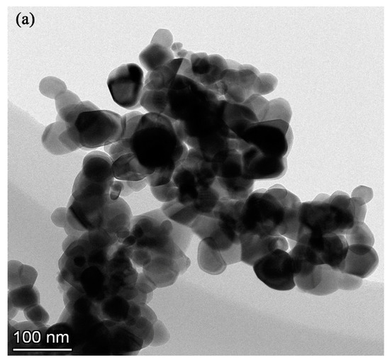
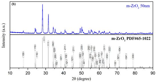
Figure 1.
(a) TEM image, (b) XRD patterns of m-ZrO2 nanopowder.

Table 1.
The detailed compositions of electrolyte.
A pulsed unipolar power supply unit was used to carry out the PEO process. A 304 stainless steel double-walled chamber containing the electrolyte was used as a cathode through which cooled water was pumped to keep the electrolyte temperature close to 20 °C. A TC21 titanium alloy rectangular sample immersed in the electrolyte was used as the anode. During the PEO process, the electrical parameters were fixed as follows: anodic current density of 10 A/dm2, frequency of 600 Hz, duty cycle of 10% and treatment time of 20 min. To ensure the uniform dispersion of m-ZrO2 nanoparticles in the electrolyte, the corresponding amount of m-ZrO2 nanoparticles was added to the prepared 2 L volume of electrolyte. After continuous stirring for 24 h, the electrolyte was ultrasonicated for 30 min and transferred to the 304 stainless steel chamber to start the PEO process. During the treatment, the electrolyte was stirred continuously. After PEO treatment, the coating samples were rinsed in deionized water and dried in air.
2.3. High Temperature Oxidation Tests
The TC21 titanium alloys and coating samples were put into an alumina crucible and placed in a muffle furnace for cyclic oxidation experiments. Before the cyclic oxidation experiments, the samples pre-dried at 150 °C were weighed together with the alumina crucibles, which were pre-dried to a constant mass at 800 °C. The cyclic oxidation experiment temperatures were 650 °C and 750 °C. The total oxidation time was 100 h. Every 10 h, the experimental samples were taken out and placed into a dryer. After cooling in static air, the mass of each sample was weighed by a Sartorius BSA 124S analytical balance (accuracy of 10−4 g).
2.4. Coating Characterization
The surface and cross-sectional morphology and elemental compositions of the PEO coatings before and after high temperature oxidation were observed by scanning electron microscopy (SEM, JSM-6460, JEOL, Tokyo, Japan) equipped with energy dispersion X-ray spectrometry (EDS, Oxford INCA, Oxford, UK). The phase composition was investigated by X-ray diffraction (XRD), using a D8 Bruker Advantage instrument (Bruker, Karlsruhe, Germany) with a step size of 0.05° and a scan range from 10° to 90° (in 2θ). Transmission electron microscopy (TEM) characterization with EDS was performed by using a FEI Talos F200X (FEI, Hillsboro, OR, USA). The TEM specimen preparation was as follows: pieces of the coating were scraped off and ground into a powder; the powder was dispersed in ethanol and ultrasonicated for 20 min; and then, several microliters of the solution was added dropwise onto a carbon-coated copper grid for subsequent TEM analysis. The zeta potentials of ZrO2 nanoparticles in the electrolyte were measured using a zeta potential analyzer (Nano zs; Malvern Panalytical, Malvern, UK).
3. Results
3.1. Surface SEM Analysis
The scanning electron micrographs of the surface of the coated samples are shown in Figure 2. The coatings prepared in four different electrolytes had a typical volcanic cone morphology, and there were different size discharge micropores in the middle and around the volcanic cones. For the coatings prepared in bath A, there were two kinds of discharge micropores on the surface. One type comprised small discharge micropores continuously distributed in the red labelled area with a diameter less than 2 μm. The other type comprised the independent discharge micropores marked in the yellow area with a large aperture of 5 to 8 μm. When the ZrO2 nanoparticles were added to the electrolyte, the number of fine discharge micropores decreased as the concentration of the nanoparticles increased. For the coating prepared in bath D, the fine discharge micropores almost disappeared. This was because with an increase in the concentration of the ZrO2 nanoparticles in the electrolyte, the thickness of the coating increased, which led to an increase in the discharge intensity. Furthermore, from the enlarged image in Figure 2, it can be observed that the fine white ZrO2 nanoparticles deposited on the surface of the coatings, which played an obvious sealing effect, and the deposition amount increased with an increase in the concentration of ZrO2 nanoparticles. Table 2 shows the porosity of the coatings determined with by ImageJ software, and the porosity of the composite coatings decreased obviously.
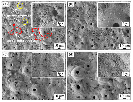
Figure 2.
Surface morphology of the plasma electrolytic oxidation (PEO) coatings formed in (a) bath A, (b) bath B, (c) bath C, and (d) bath D.
Table 2.
Area energy dispersion X-ray spectrometry (EDS) analysis, thickness, and porosity of the PEO coatings.
Table 2 shows the EDS surface scan results for each coating surface. As the concentration of ZrO2 nanoparticles in the electrolyte increased, the content of aluminum and titanium in the coatings gradually decreased, and the content of zirconium increased. This also indicated that deposition of the ZrO2 nanoparticles occurred.
3.2. Cross-Sectional SEM Analysis
As shown in Figure 3, all the coated samples showed good adhesion to the substrate without any discontinuity at the interface. The results of elemental mapping showed that Al, Ti, O, and Zr elements were uniformly distributed in the coatings. Table 2 shows the thickness increased with an increase in the concentration of ZrO2 nanoparticles.
Figure 3.
Cross-sectional morphology of the PEO coatings formed in (a) bath A, (b) bath B, (c) bath C, and (d) bath D. (e) EDS elemental mapping of the sample formed in bath C.
3.3. Phase Composition
The X-ray diffraction peaks of the coatings formed in baths A, B, C, and D are shown in Figure 4. The coated samples prepared in bath A consisted mainly of Al2TiO5. Alpha and beta titanium peaks in the TC21 alloy spectra can still be observed because of the relatively low atomic number, thin thickness, and high porosity of the coated samples.
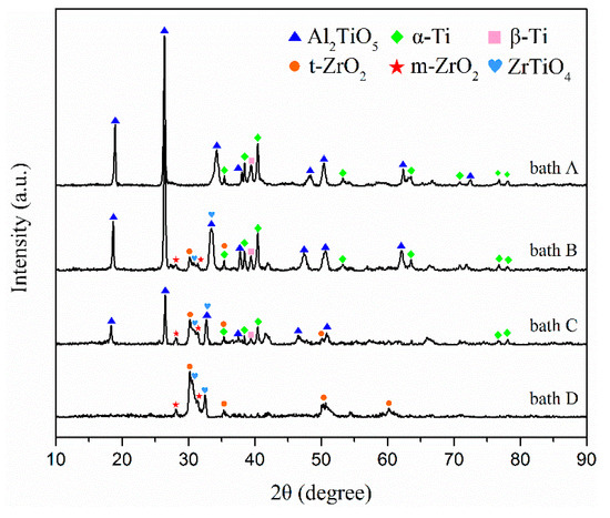
Figure 4.
XRD patterns of the PEO coatings formed in baths A, B, C, and D.
The m-ZrO2, tetragonal-ZrO2 (t-ZrO2), and ZrTiO4 can be observed in the composite coatings prepared in baths B, C, and D. At the same time, it can be observed that the alpha and beta titanium peaks for TC21 alloy in the spectra decreased gradually. One reason was the composite coating contained zirconium, which has a large atomic number. Another reason was that as the ZrO2 concentration increased, the coating thickness increased and the porosity decreased. Titanium peaks were not observed in the coatings prepared in bath D. In addition, with an increase in the concentration of ZrO2 nanoparticles in the electrolyte, the peak strength of Al2TiO5 decreased gradually, which also indicated that ZrO2 nanoparticles were deposited on the coating surface.
3.4. TEM Analysis
The TEM image of pieces scraped off the coatings formed in bath C is shown in Figure 5a. The EDS maps showed in Figure 5b–e indicate that the coating contained zirconium, aluminum, oxygen, and titanium. As shown in Figure 5f–j, various lattice fringes can be observed in the HRTEM image of area A. The crystal plane spacing obtained from the lattice fringes in area 1, area 2, area 3, and area 4 were 0.336 nm, 0.316 nm, 0.297 nm, and 0.293 nm, respectively, which correspond to the (110) crystal plane of Al2TiO5, (−111) crystal plane of m-ZrO2, (111) crystal plane of t-ZrO2, and (111) crystal plane of ZrTiO4, respectively.
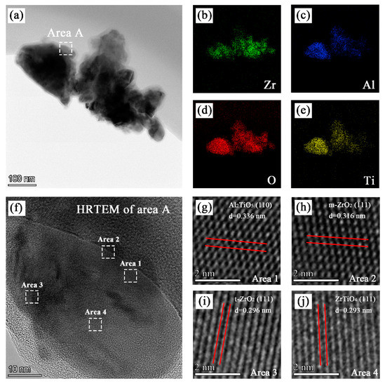
Figure 5.
TEM, EDS, and HRTEM analysis of the PEO coating formed in bath C: (a) TEM images; (b), (c), (d), and (e) EDS mapping of the distribution of zirconium, aluminum, oxygen, and titanium, respectively; and (f), (g), (h), (i), and (j) HRTEM images of certain regions.
3.5. Oxidation Kinetics
Figure 6 depicts the oxidation kinetics curves of the uncoated and coated TC21 alloys after cyclic oxidation at 650 °C and 750 °C. The weights of the four kinds of coatings decreased at the beginning of cyclic oxidation at 650 °C. Literature reports indicate that the coatings contain unstable hydrated compounds or carbonates, which decompose during the initial stage of high temperature oxidation, resulting in a decrease in the weight [30]. After 20 h of high temperature oxidation, the weight of the four coatings began to increase with the oxidation time. However, after several cycles, the coating quality was almost unchanged from 60 h of oxidation time and onward. The weight of the TC21 alloys continued to increase rapidly during the first 60 h of the oxidation experiment. Although there was still obvious weight gain after 60 h, the growth rate gradually slowed. Finally, after 100 h of oxidation, the weight change of the TC21 alloys was 0.41 mg/cm2, and the weight change of coated samples prepared in baths A, B, C, and D was 0.086 mg/cm2, 0.077 mg/cm2, 0.079 mg/cm2, and 0.071 mg/cm2, respectively, which was nearly five times lower than that of TC21 alloys.
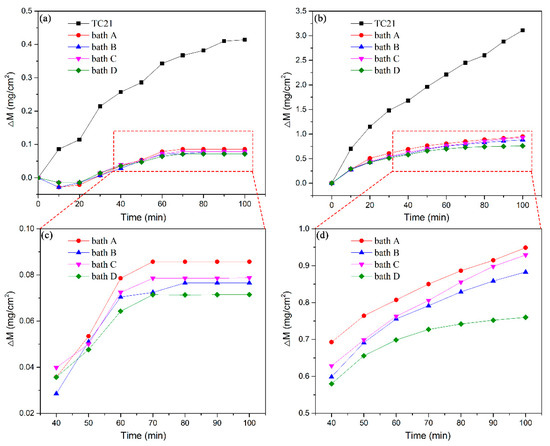
Figure 6.
Oxidation kinetic curves of TC21 alloys and the PEO coatings oxidized at different temperatures: (a) and (c) 650 °C and (b) and (d) 750 °C.
During the cyclic oxidation experiment at 750 °C, the slopes of the curves for the TC21 alloys were very large during the first 20 h. After 20 h, the slopes decreased slightly, but the weights still increased almost linearly. The weight change was 3.11 mg/cm2 after 100 h of oxidation. The oxidation kinetic curves for the four kinds of coatings were pseudo-parabolic. The weight gain of the composite coatings prepared in baths B, C, and D were 0.88 mg/cm2, 0.93 mg/cm2, and 0.76 mg/cm2 respectively, which were slightly lower than that of the coatings prepared in bath A, which was 0.95 mg/cm2.
The high temperature cyclic oxidation experiments at both temperatures showed that the PEO coatings can significantly improve the high temperature oxidation resistance of TC21 alloys. The high temperature oxidation resistance of the ZrO2 composite coatings was slightly better than that of the conventional coatings.
3.6. SEM/XRD Analysis of the PEO Coatings after Cyclic Oxidation
Figure 7 shows the XRD spectra of TC21 alloys and PEO coatings after high temperature cyclic oxidation at 650 °C and 750 °C. (The results of coatings produced in bath B and bath C were similar. Figure 7 gives only the results of the coating produced in bath B).
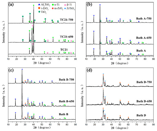
Figure 7.
XRD patterns of (a) TC21 alloys and the PEO coatings formed in (b) bath A, (c) bath B, and (d) bath D after high temperature oxidation tests.
Rutile can be observed for the TC21 alloys because the transition temperature from anatase to rutile is 600 °C ~ 1000 °C. With the increase of oxidation temperature, the intensity of the rutile peaks increased and the peak intensities of α-Ti and β-Ti decreased.
For coatings produced in baths A, B, and C, the phenomenon was similar to that for the TC21 alloys after high temperature oxidation. Rutile was found in all these coatings, but no Al2O3 peak was observed, which indicated that the Al2TiO5 phase in the coatings was stable and did not decompose during high temperature oxidation. The rutile came from the oxidation of the titanium matrix.
Although weight gain occurred, rutile was not observed in the coatings produced in bath D after high temperature oxidation. This was because the coatings themselves were thick, and the oxidation weight gain was very small, indicating that the formation of rutile was relatively small.
Figure 8 shows the surface and cross-sectional microstructures of the PEO coatings after oxidation at 750 °C. Some distinct cracks appeared on the surface of the coatings. The cracks in the coatings prepared in baths A and B were relatively few in number, while number of the cracks in the coatings prepared in baths C and D were obviously increased. From the cross-sectional morphology, it can be seen that the porosity increased slightly compared with that before oxidation. Vertical cracks can be observed in sample D. In addition, an interlayer of approximately 4 μm in thickness was formed at the interface between the TC21 alloys and coatings. The composition of the interlayers in atom percentage was as follows: point A (Ti 42.8%, O 56.6%, and Al 0.6%), point B (Ti 42.6%, O 56.6%, Al 0.4%, and Zr 0.4%), point E (Ti 39.1%, O 59.8%, Al 0.7%, and Zr 0.4%), and point F (Ti 41.3%, O 57.2%, Al 0.5%, and Zr 0.5%). The results showed that an oxide layer formed at the interface. However, in addition to rutile, there should be enrichment of titanium atoms in the interlayer. In addition, the low aluminum content meant that a small amount of alumina was produced during the oxidation process, which resulted in no corresponding peak on the XRD spectrum.
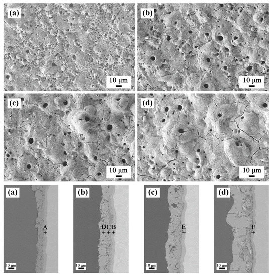
Figure 8.
Surface and cross-sectional morphologies of the PEO coatings after 750 °C oxidation tests: (a) bath A, (b) bath B, (c) bath C, and (d) bath D.
The above results were because the formation free energy and equilibrium oxygen pressure of Al/Al2O3 and Ti/TiO2 are similar, and the formation rate of TiO2 and Al2O3 is almost the same at the beginning of oxidation. However, the growth activation energy of TiO2 are significantly lower than that of Al2O3, and the formation rate of TiO2 was faster in subsequent stages [31]. Moreover, the composition of point C in atom percentage was (Ti 9.4%, O 57.0%, Al 28.5%, and Zr 5.1%) and that of point D was (Ti 9.7%, O 56.1%, Al 29.0%, and Zr 5.2%), which showed that the coatings themselves did not change during the oxidation process.
4. Discussion
4.1. Nanoparticle Deposition Mechanism
The deposition mechanism of the nanoparticles in the PEO coatings is determined by many factors, such as the substrate, electrolyte, and electrical parameters. The ZrO2 nanoparticles in this experiment were found to achieve partly reactive incorporation, resulting in the inclusion of m-ZrO2, t-ZrO2, and ZrTiO4 in the coatings. The zeta potential of the m-ZrO2 nanoparticles was −30 mV in alkaline electrolytes. They migrated to the anode and deposited on the coating surface inertly during the electrophoresis and mechanical stirring processes. In addition, the molten oxide ejected from the discharge micropores also enclosed the m-ZrO2 nanoparticles near the anode. The active deposition of m-ZrO2 nanoparticles included two aspects. First, the m-ZrO2 underwent phase transformation to form t-ZrO2. Second, ZrO2 nanoparticles that reacted with melted TiO2 formed during the PEO process and formed ZrTiO4. The m-ZrO2 transformed to t-ZrO2 at 1200 °C and t-ZrO2 transformed to c-ZrO2 at 2370 °C [32]. The formation temperature of ZrTiO4 ranged from 1100 °C ~ 1200 °C [33]. In summary, the reaction temperature of the experimental process should be between 1373 °C and 2370 °C.
4.2. High Temperature Oxidation Behavior and Mechanism
The essence of high temperature oxidation is that metal ions and oxygen molecules diffuse through the oxide coating and react when they meet. As shown in Figure 9a, the oxidation mechanism in this experiment was that the oxygen molecules diffuse inward, and preferentially reacted with the titanium atoms to form a layer of rutile at the interface between the coatings and TC21 alloys. The oxidation kinetics curves show that the PEO coatings substantially hindered the diffusion of the oxygen molecules. The oxidation weight gain of the coated samples was significantly smaller than that of the TC21 alloys. The protective property of the coatings was also better than that of the oxide spontaneously formed during the oxidation process of the TC21 alloys at high temperature. However, the discharge micropores on the surface of the coating inevitably became the diffusion channel for the oxygen molecules. With increasing oxidation temperature, the diffusion rate of the oxygen molecules through the coating increased, and the reaction rate of the metal/oxide interface increased, resulting in an increased oxidation reaction.
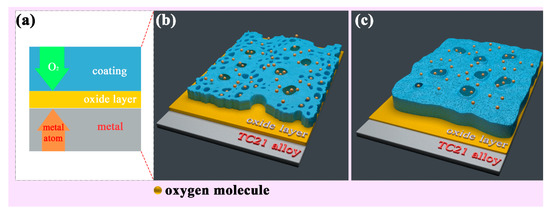
Figure 9.
two-dimension (a) and three-dimension schematic diagram of the high temperature oxidation mechanism of the PEO coatings formed (b) without ZrO2 and (c) with ZrO2.
Figure 9b,c show that the surface porosity of conventional PEO coatings was relatively large, and the oxygen molecule diffusion channel increased accordingly. The coating was relatively thin and the resistance to oxygen diffusion was comparatively weak. For the composite coatings, the thickness of the coating was significantly increased, and the ability to block oxygen molecules was increased. The porosity of the coating was significantly reduced due to the deposition of the nanoparticles on the surface of the coating and the barrier effect on the oxygen molecules was further enhanced. In addition, the composite coatings contained m-ZrO2, t-ZrO2, and ZrTiO4, which are stable at high temperatures, have a low thermal expansion coefficient, and do not readily delaminate and decompose at high temperatures [34]. Therefore, the high temperature oxidation resistance of the composite coatings was better than that of the conventional coatings.
5. Conclusions
Ceramic composite coatings were formed on TC21 alloys by plasma electrolytic oxidation using a m-ZrO2 nanoparticle suspension as the electrolyte. The high temperature oxidation behavior and mechanism at 650°C and 750°C were investigated. The following conclusions can be drawn:
- The composite coatings were mainly composed of m-ZrO2, t-ZrO2, and ZrTiO4, indicating that ZrO2 nanoparticles achieved partial reactive incorporation.
- As the concentration of ZrO2 nanoparticles in the electrolyte increased, the thickness of the composite coating increased and the porosity decreased.
- The high temperature oxidation resistance of TC21 alloys was improved by 3–5 times after PEO treatment, and that of the composite coatings were improved by nearly 20% compared with that of the conventional coatings.
Author Contributions
K.Z. drafted the manuscript and performed the experiments; F.X. contributed to the conception of the study; X.W. and S.W. performed the data analyses and revised the manuscript. All authors have read and agreed to the published version of the manuscript.
Funding
This research was funded by The Science and Technology Program for Research and Development of Shaanxi Province. (2018JZ5004).
Conflicts of Interest
The authors declare no conflict of interest.
References
- Boyer, R.R. An overview on the use of titanium in the aerospace industry. Mater. Sci. Eng. A 1996, 213, 103–114. [Google Scholar] [CrossRef]
- Huda, Z.; Edi, P. Materials selection in design of structures and engines of supersonic aircrafts: A review. Mater. Des. 2013, 46, 552–560. [Google Scholar] [CrossRef]
- Peters, M.; Kumpfert, J.; Ward, C.H.; Leyens, C. Titanium Alloys for Aerospace Applications. Adv. Eng. Mater. 2003, 5, 419–427. [Google Scholar] [CrossRef]
- Zhu, Y.S.; Lu, W.Z.; Zuo, D.W.; Cao, D.W. A novel rare earth-salt bath nitriding of TC21-DT titanium alloy. Surf. Eng. 2018, 34, 128–131. [Google Scholar] [CrossRef]
- Liu, W.; Liang, W.; Miao, Q.; Pan, X.; Ren, B. Preparation and oxidation resistance of Al-Cr composite coating on TC21 alloy surface. J. Nanjing Univ. Aeronaut. Astronaut. 2015, 47, 702–708. [Google Scholar] [CrossRef]
- Hosseini, S.H.; Mirdamadi, S.; Rastegari, S. Investigating efficiency of α-Al2O3 diffusion barrier layer in oxidation of EB-PVD NiCrAlY coatings. Surf. Eng. 2015, 31, 146–155. [Google Scholar] [CrossRef]
- Ghosh, D.; Das, S.; Roy, H.; Mitra, S.K. Oxidation behaviour of nanostructured YSZ plasma sprayed coated Inconel alloy. Surf. Eng. 2018, 34, 22–29. [Google Scholar] [CrossRef]
- Chaliampalias, D.; Pistofidis, N.; Pavlidou, E.; Tsipas, D.; Stergioudis, G.; Vourlias, G. Resistance of different Zn coatings at elevated temperature air environments. Surf. Eng. 2016, 32, 53–60. [Google Scholar] [CrossRef]
- Zhuang, Q.; Zhang, P.; Li, M.; Yan, H.; Yu, Z.; Lu, Q. Microstructure, Wear Resistance and Oxidation Behavior of Ni-Ti-Si Coatings Fabricated on Ti6Al4V by Laser Cladding. Materials 2017, 10, 1248. [Google Scholar] [CrossRef]
- Liang, J.; Chen, S.; Zou, C.; Tian, C.; Wang, Z.; Liao, S. Influence of Oxygen Contents on the Microstructure, High Temperature Oxidation and Corrosion Resistance Properties of Cr–Si–O–N Coatings. Coatings 2018, 8, 19. [Google Scholar] [CrossRef]
- Ye, F.; Zhao, L.; Mu, C.; Zhao, H. Influence of yttrium addition on reactive sputtered W–Y–N coatings. Surf. Eng. 2017, 33, 626–632. [Google Scholar] [CrossRef]
- Sayyedan, F.S.; Enayati, M.H. On structure and oxidation behaviour of non-stoichiometric amorphous aluminum phosphate coating. Surf. Eng. 2019, 35, 670–676. [Google Scholar] [CrossRef]
- Ding, Z.-Y.; Wang, Y.-H.; Ouyang, J.-H.; Liu, Z.-G.; Wang, Y.-M.; Wang, Y.-J. Influence of Al2O3 addition in NaAlO2 electrolyte on microstructure and high-temperature properties of plasma electrolytic oxidation ceramic coatings on Ti2AlNb alloy. Surf. Coat. Technol. 2019, 370, 187–195. [Google Scholar] [CrossRef]
- Yerokhin, A.L.; Nie, X.; Leyland, A.; Matthews, A.; Dowey, S.J. Plasma electrolysis for surface engineering. Surf. Coat. Technol. 1999, 122, S0257–S8972. [Google Scholar] [CrossRef]
- Tao, X.; Yao, Z.; Luo, X. Comparison of tribological and corrosion behaviors of Cp Ti coated with the TiO2/graphite coating and nitrided TiO2/graphite coating. J. Alloys Compd. 2017, 718, 126–133. [Google Scholar] [CrossRef]
- Tekin, K.C.; Malayoglu, U.; Shrestha, S. Tribological behaviour of plasma electrolytic oxide coatings on Ti6Al4V and cp-Ti alloys. Surf. Eng. 2016, 32, 435–442. [Google Scholar] [CrossRef]
- Ren, L.; Wang, T.; Chen, Z.; Li, Y.; Qian, L. Self-Lubricating PEO–PTFE Composite Coating on Titanium. Metals 2019, 9, 170. [Google Scholar] [CrossRef]
- Qin, Y.; Xiong, D.; Li, J.; Jin, Q.; He, Y.; Zhang, R.; Zou, Y. Adaptive-lubricating PEO/Ag/MoS2 multilayered coatings for Ti6Al4V alloy at elevated temperature. Mater. Des. 2016, 107, 311–321. [Google Scholar] [CrossRef]
- Zhang, R.; Liu, X.; Xiong, Z.; Huang, Q.; Yang, X.; Yan, H.; Ma, J.; Feng, Q.; Shen, Z. Novel micro/nanostructured TiO2/ZnO coating with antibacterial capacity and cytocompatibility. Ceram. Int. 2018, 44, 9711–9719. [Google Scholar] [CrossRef]
- Hakimizad, A.; Raeissi, K.; Golozar, M.A.; Lu, X.; Blawert, C.; Zheludkevich, M.L. Influence of cathodic duty cycle on the properties of tungsten containing Al2O3/TiO2 PEO nano-composite coatings. Surf. Coat. Technol. 2018, 340, 210–221. [Google Scholar] [CrossRef]
- Muhaffel, F.; Kaba, M.; Cempura, G.; Derin, B.; Kruk, A.; Atar, E.; Cimenoglu, H. Influence of alumina and zirconia incorporations on the structure and wear resistance of titania-based MAO coatings. Surf. Coat. Technol. 2019, 377, 124900. [Google Scholar] [CrossRef]
- Barati, N.; Meletis, E.I. Al2O3-ZrO2 nanocomposites coating on aluminum alloy by plasma electrolytic-electrophoretic hybrid process. Mater. Today Commun. 2019, 19, 1–11. [Google Scholar] [CrossRef]
- Lu, X.; Chen, Y.; Blawert, C.; Li, Y.; Zhang, T.; Wang, F.; Kainer, U.K.; Zheludkevich, M. Influence of SiO2 Particles on the Corrosion and Wear Resistance of Plasma Electrolytic Oxidation-Coated AM50 Mg Alloy. Coatings 2018, 8, 306. [Google Scholar] [CrossRef]
- Atapour, M.; Blawert, C.; Zheludkevich, M.L. The wear characteristics of CeO2 containing nanocomposite coating made by aluminate-based PEO on AM 50 magnesium alloy. Surf. Coat. Technol. 2019, 357, 626–637. [Google Scholar] [CrossRef]
- Lu, X.; Blawert, C.; Kainer, K.U.; Zheludkevich, M.L. Investigation of the formation mechanisms of plasma electrolytic oxidation coatings on Mg alloy AM50 using particles. Electrochim. Acta 2016, 196, 680–691. [Google Scholar] [CrossRef]
- Fatimah, S.; Kamil, M.P.; Kwon, J.H.; Kaseem, M.; Ko, Y.G. Dual incorporation of SiO2 and ZrO2 nanoparticles into the oxide layer on 6061 Al alloy via plasma electrolytic oxidation: Coating structure and corrosion properties. J. Alloys Compd. 2017, 707, 358–364. [Google Scholar] [CrossRef]
- Gowtham, S.; Hariprasad, S.; Arunnellaiappan, T.; Rameshbabu, N. An investigation on ZrO2 nano-particle incorporation, surface properties and electrochemical corrosion behaviour of PEO coating formed on Cp-Ti. Surf. Coat. Technol. 2017, 313, 263–273. [Google Scholar] [CrossRef]
- Rehman, Z.U.; Shin, S.H.; Lim, H.-T.; Koo, B.H. Transformation of plasma electrolytic oxidation coatings from crater to cluster–based structure with increase in DC voltage and the role of ZrO2 nanoparticles. Surf. Coat. Technol. 2017, 311, 383–390. [Google Scholar] [CrossRef]
- Eslamzadeh, N.; Ebrahimi-Kahrizsangi, R.; Karbasi, S.; Zarebidaki, A.; Gharavi, F. An Investigation into the Corrosion Behavior of MgO/ZrO2 Nanocomposite Coatings Prepared by Plasma Electrolytic Oxidation on the AZ91 Magnesium Alloy. J. Mater. Eng. Perform. 2017, 26, 4255–4264. [Google Scholar] [CrossRef]
- Xu, Y.; Yao, Z.; Jia, F.; Wang, Y.; Jiang, Z.; Bu, H. Preparation of PEO ceramic coating on Ti alloy and its high temperature oxidation resistance. Curr. Appl. Phys. 2010, 10, 698–702. [Google Scholar] [CrossRef]
- Dai, J.; Zhu, J.; Chen, C.; Weng, F. High temperature oxidation behavior and research status of modifications on improving high temperature oxidation resistance of titanium alloys and titanium aluminides: A review. J. Alloys Compd. 2016, 685, 784–798. [Google Scholar] [CrossRef]
- Matykina, E.; Arrabal, R.; Monfort, F.; Skeldon, P.; Thompson, G.E. Incorporation of zirconia into coatings formed by DC plasma electrolytic oxidation of aluminum in nanoparticle suspensions. Appl. Surf. Sci. 2008, 255, 2830–2839. [Google Scholar] [CrossRef]
- Li, H.; Sun, Y.; Zhang, J. Effect of ZrO2 particle on the performance of micro-arc oxidation coatings on Ti6Al4V. Appl. Surf. Sci. 2015, 342, 183–190. [Google Scholar] [CrossRef]
- Wang, C.; Hao, J.; Xing, Y.; Guo, C.; Chen, H. High temperature oxidation behavior of TiO2+ZrO2 composite ceramic coatings prepared by microarc oxidation on Ti6Al4V alloy. Surf. Coat. Technol. 2015, 261, 201–207. [Google Scholar] [CrossRef]


© 2019 by the authors. Licensee MDPI, Basel, Switzerland. This article is an open access article distributed under the terms and conditions of the Creative Commons Attribution (CC BY) license (http://creativecommons.org/licenses/by/4.0/).