Bird-Strike Resistance of Composite Laminates with Different Materials


Abstract
:1. Introduction
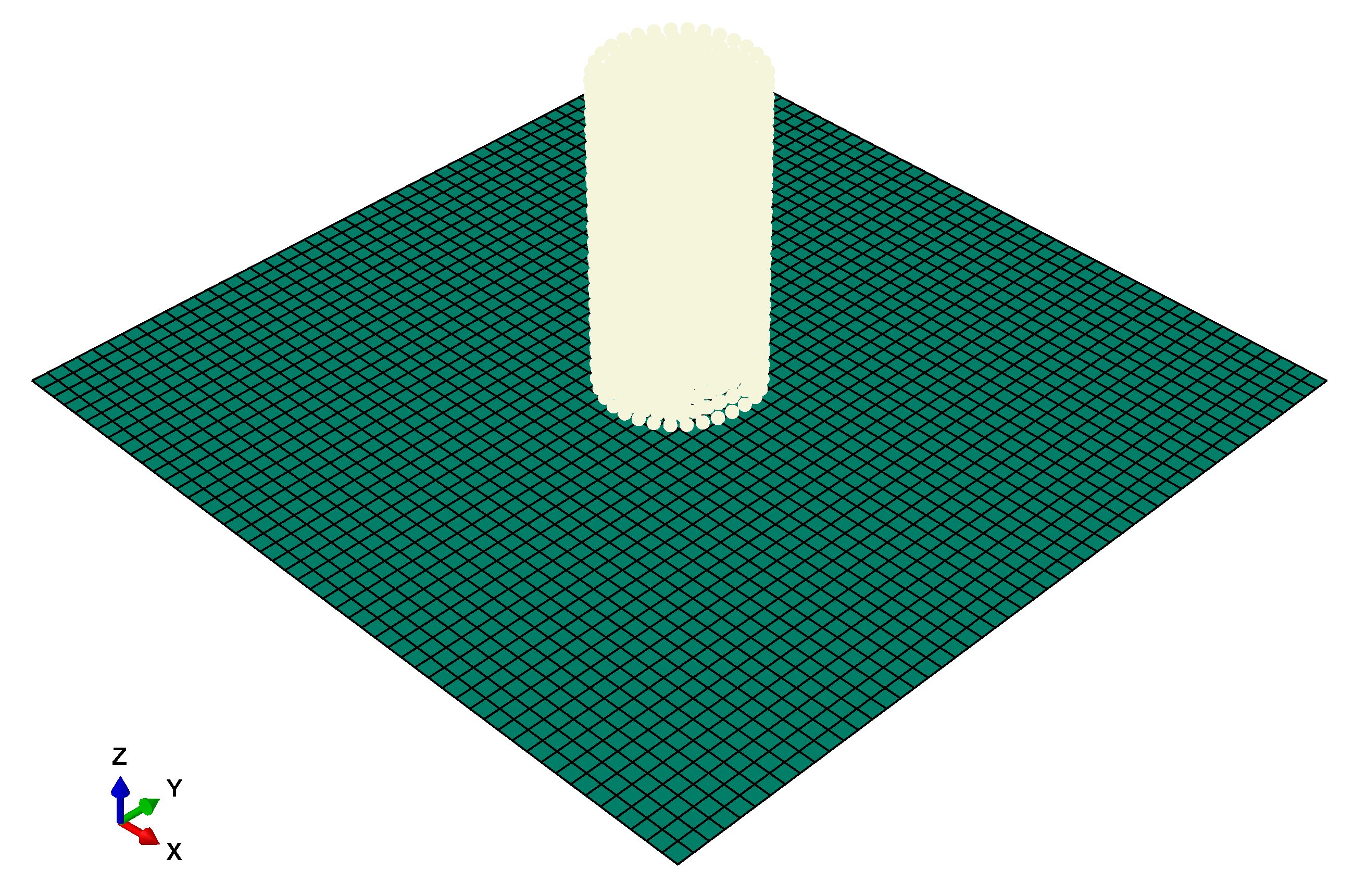
2. Numerical Model
3. Results and Discussion
4. Conclusions
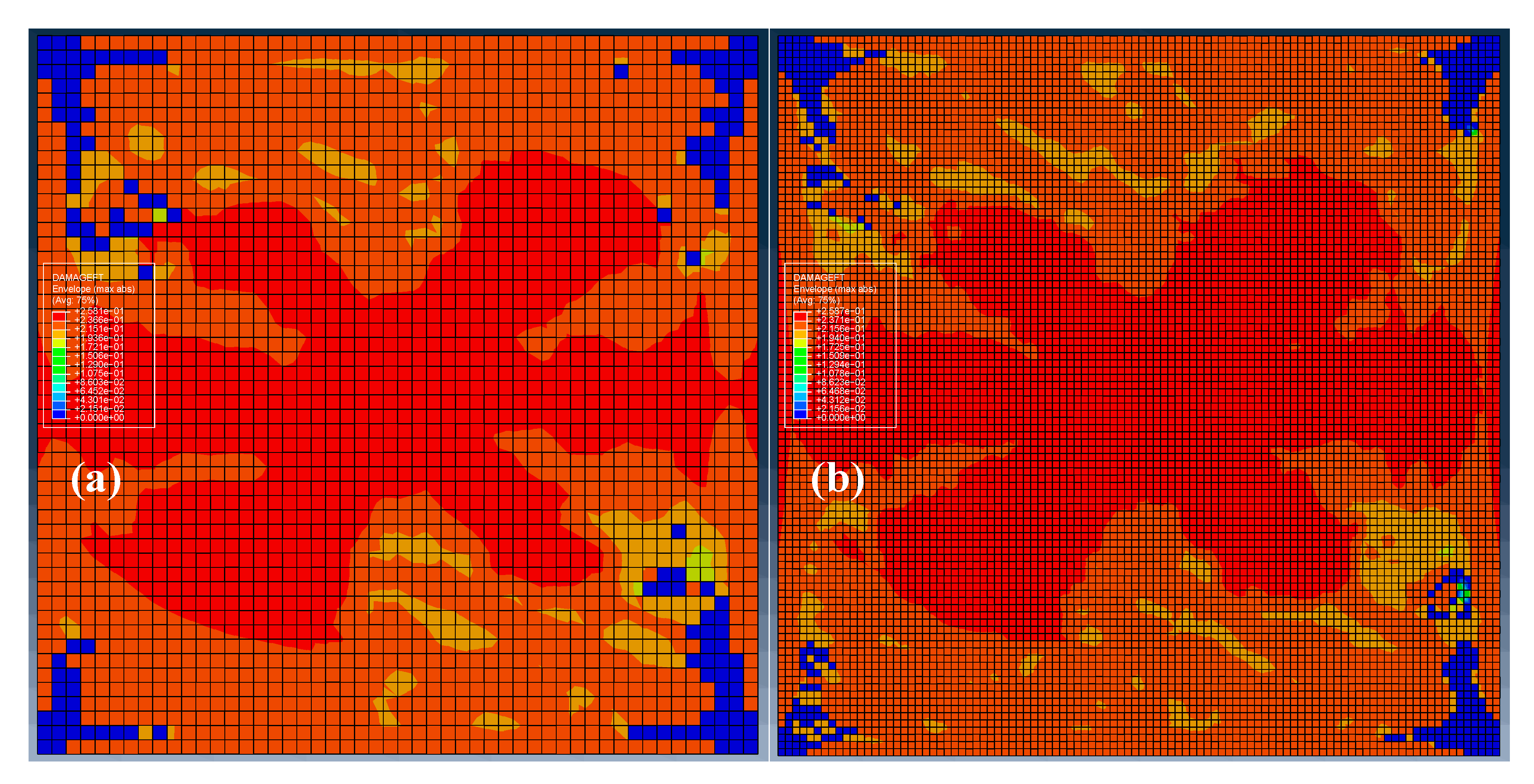
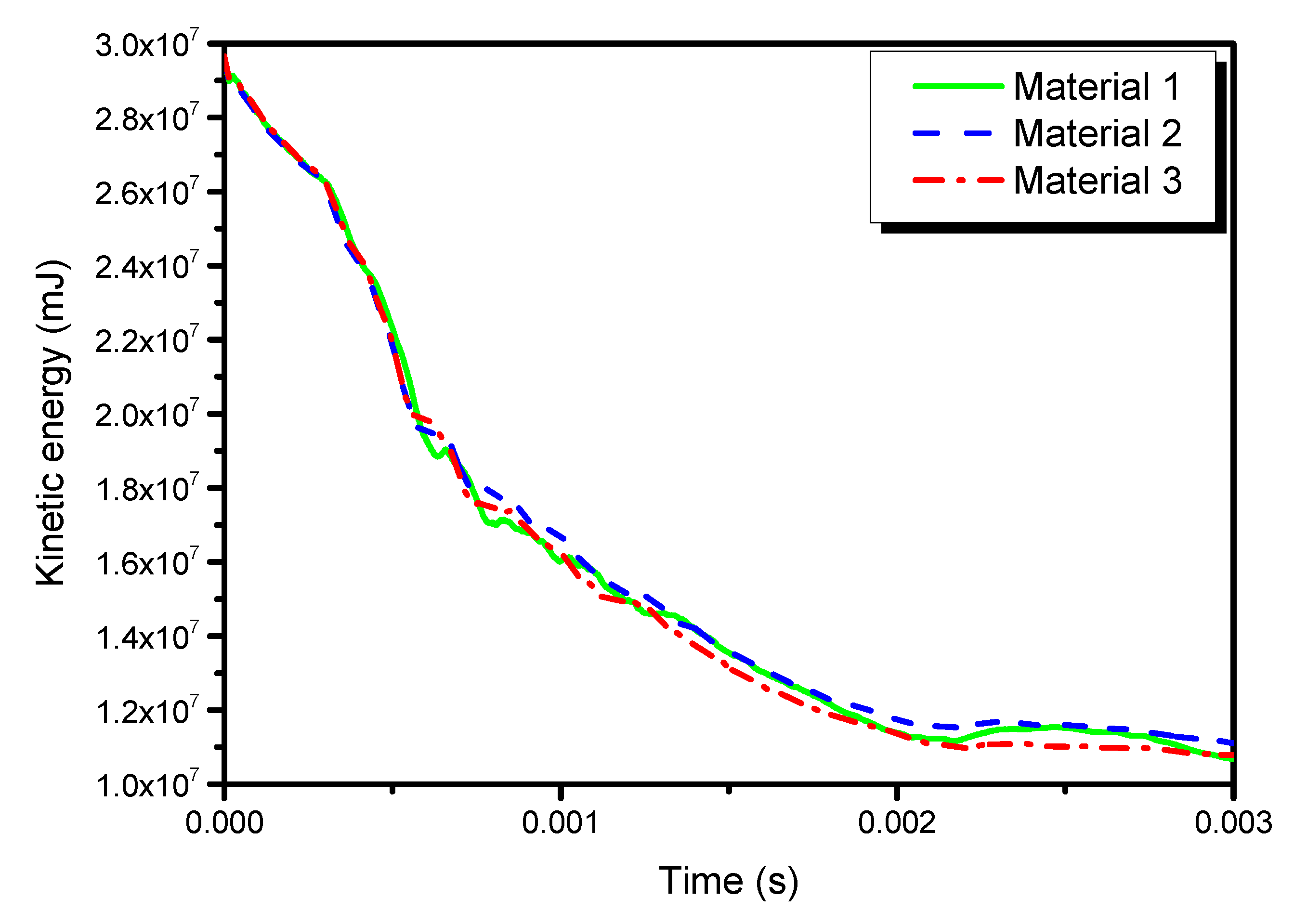
- Results show that the different composite materials (with the same reinforced fibers) have little effect on projectile deformations during the bird impact;
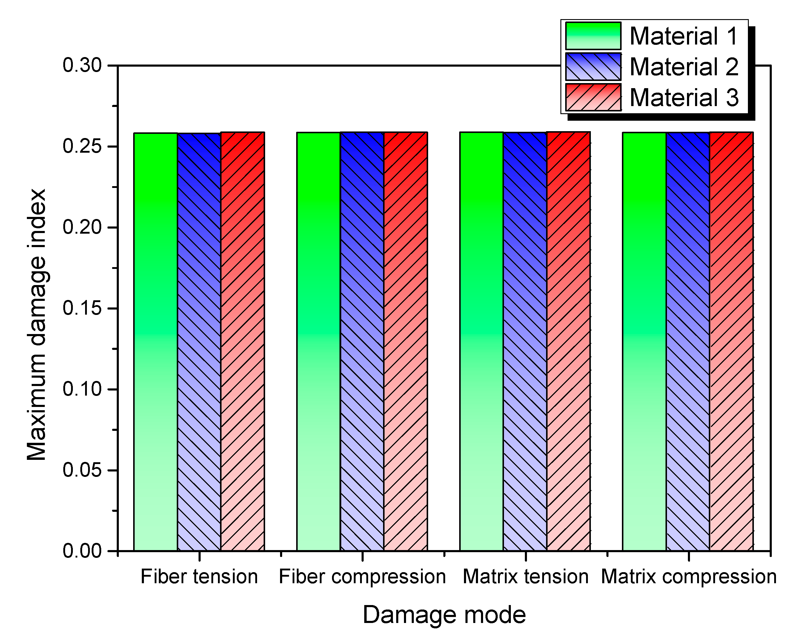
- The fiber tension damage is mainly governed by the fiber tension strength, while the longitudinal tensile fracture energy has little effect on it;
- The compressive strength parameters determine the severity of fiber compression damage, while the compressive fracture energy determines the damage distribution patterns;
- The three composite materials have similar distribution patterns in the matrix compression damage, while the most severe matrix compression damage appeared in material 3, due to its weakest shear strengths;
- The parameters YT and S12 are the most influential factors for the matrix tension damage, while the tensile fracture energies have little influence;
- Modal frequency was tentatively used to explain the damage behavior of the composite laminates, for it can manifest both the mass and stiffness characteristics of a dynamic structure. The dynamic properties and strength properties jointly determine the impact damage resistance of composite laminates under bird strike.
Author Contributions
Funding
Acknowledgments
Data Availability Statement
Conflicts of Interest
References
- Abrate, S. Soft impacts on aerospace structures. Prog. Aerosp. Sci. 2016, 81, 1–17. [Google Scholar] [CrossRef] [Green Version]
- Zhang, D.; Fei, Q. Effect of bird geometry and impact orientation in bird striking on a rotary jet-engine fan analysis using SPH method. Aerosp. Sci. Technol. 2016, 54, 320–329. [Google Scholar] [CrossRef]
- Mao, R.; Meguid, S.A.; Ng, T.Y. Finite Element Modeling of a Bird Striking an Engine Fan Blade. J. Aircr. 2007, 44, 583–596. [Google Scholar] [CrossRef]
- Liu, J.; Zhong, D.; Li, Y.; Tang, Z.; Gao, X.; Zhang, Z.; Huang, F. Numerical simulation and test on damage of rotary engine blades impacted by bird. Int. J. Crashworthines 2019, 24, 106–120. [Google Scholar] [CrossRef]
- Vignjevic, R.; Orłowski, M.; De Vuyst, T.; Campbell, J.C. A parametric study of bird strike on engine blades. Int. J. Impact Eng. 2013, 60, 44–57. [Google Scholar] [CrossRef]
- Guida, M.; Sellitto, A.; Marulo, F.; Riccio, A. Analysis of the Impact Dynamics of Shape Memory Alloy Hybrid Composites for Advanced Applications. Materials 2019, 12, 153. [Google Scholar] [CrossRef] [Green Version]
- Di Caprio, F.; Cristillo, D.; Saputo, S.; Guida, M.; Riccio, A. Crashworthiness of wing leading edges under bird impact event. Compos. Struct. 2019, 216, 39–52. [Google Scholar] [CrossRef]
- Guida, M.; Marulo, F.; Polito, T.; Meo, M.; Riccio, M. Design and Testing of a Fiber-Metal-Laminate Bird-Strike-Resistant Leading Edge. J. Aircr. 2009, 46, 2121–2129. [Google Scholar] [CrossRef] [Green Version]
- Diamantakos, I.; Fotopoulos, K.; Jamin, M.; Eberhardt, A.; Lampeas, G. Investigation of bird strike events on composite wing panels. Fatigue Fract. Eng. M. 2017, 40, 1538–1550. [Google Scholar] [CrossRef]
- McCarthy, M.A.; Xiao, J.R.; McCarthy, C.T.; Kamoulakos, A.; Ramos, J.; Gallard, J.P.; Melito, V. Modelling of Bird Strike on an Aircraft Wing Leading Edge Made from Fibre Metal Laminates—Part 2: Modelling of Impact with SPH Bird Model. Appl. Compos. Mater. 2004, 11, 317–340. [Google Scholar] [CrossRef]
- Kermanidis, T.; Labeas, G.; Sunaric, M.; Johnson, A.F.; Holzapfel, M. Bird strike simulation on a novel composite leading edge design. Int. J. Crashworthines 2006, 11, 189–202. [Google Scholar] [CrossRef]
- Cai, J.; Bao, H.; Zuo, H.; Huang, Y. Safety evaluation of airworthiness requirement of bird-strike on aeroplane. Eng. Fail. Anal. 2019, 102, 407–416. [Google Scholar] [CrossRef]
- Grimaldi, A.; Sollo, A.; Guida, M.; Marulo, F. Parametric study of a SPH high velocity impact analysis – A birdstrike windshield application. Compos. Struct. 2013, 96, 616–630. [Google Scholar] [CrossRef]
- Hedayati, R.; Ziaei-Rad, S.; Eyvazian, A.; Hamouda, A.M. Bird strike analysis on a typical helicopter windshield with different lay-ups. J. Mech. Sci. Technol. 2014, 28, 1381–1392. [Google Scholar] [CrossRef]
- Hedayati, R.; Sadighi, M. Effect of Using an Inner Plate between Two Faces of a Sandwich Structure in Resistance to Bird-Strike Impact. J. Aerosp. Eng. 2016, 29, 04015020. [Google Scholar] [CrossRef]
- Mohagheghian, I.; Wang, Y.; Zhou, J.; Yu, L.; Guo, X.; Yan, Y.; Charalambides, M.N.; Dear, J.P. Deformation and damage mechanisms of laminated glass windows subjected to high velocity soft impact. Int. J. Solids Struct. 2017, 109, 46–62. [Google Scholar] [CrossRef]
- Mohagheghian, I.; Charalambides, M.N.; Wang, Y.; Jiang, L.; Zhang, X.; Yan, Y.; Kinloch, A.J.; Dear, J.P. Effect of the polymer interlayer on the high-velocity soft impact response of laminated glass plates. Int. J. Impact Eng. 2018, 120, 150–170. [Google Scholar] [CrossRef]
- Kaboglu, C.; Mohagheghian, I.; Zhou, J.; Guan, Z.; Cantwell, W.; John, S.; Blackman, B.R.K.; Kinloch, A.J.; Dear, J.P. High-velocity impact deformation and perforation of fibre metal laminates. J. Mater. Sci. 2018, 53, 4209–4228. [Google Scholar] [CrossRef] [Green Version]
- Liu, X.; Gu, W.; Liu, Q.; Lai, X.; Liu, L. Damage of Hygrothermally Conditioned Carbon Epoxy Composites under High-Velocity Impact. Materials 2018, 11, 2525. [Google Scholar] [CrossRef] [Green Version]
- Wagner, T.; Heimbs, S.; Franke, F.; Burger, U.; Middendorf, P. Experimental and numerical assessment of aerospace grade composites based on high-velocity impact experiments. Compos. Struct. 2018, 204, 142–152. [Google Scholar] [CrossRef]
- Sun, M.; Chang, M.; Wang, Z.; Li, H.; Liu, Y. Simulation of Eccentric Impact of Square and Rectangular Composite Laminates Embedded with SMA. Materials 2018, 11, 2371. [Google Scholar] [CrossRef] [PubMed] [Green Version]
- Liu, J.; Liu, H.; Kaboglu, C.; Kong, X.; Ding, Y.; Chai, H.; Blackman, B.R.K.; Kinloch, A.J.; Dear, J.P. The Impact Performance of Woven-Fabric Thermoplastic and Thermoset Composites Subjected to High-Velocity Soft- and Hard-Impact Loading. Appl. Compos. Mater. 2019, 26, 1389–1410. [Google Scholar] [CrossRef] [Green Version]
- Zhou, Y.; Sun, Y.; Huang, T.; Cai, W. SPH-FEM simulation of impacted composite laminates with different layups. Aerosp. Sci. Technol. 2019, 95, 105469. [Google Scholar] [CrossRef]
- Zhou, Y.; Sun, Y.; Huang, T. SPH-FEM Design of Laminated Plies under Bird-Strike Impact. Aerospace 2019, 6, 112. [Google Scholar] [CrossRef] [Green Version]
- Zhou, Y.; Sun, Y.; Cai, W. Bird-striking damage of rotating laminates using SPH-CDM method. Aerosp. Sci. Technol. 2019, 84, 265–272. [Google Scholar] [CrossRef]
- Zhou, Y.; Sun, Y.; Huang, T. Impact responses of slender composite plates for bird-strike testing of fan blades. Lat. Am. J. Solids Struct. 2019, 16. [Google Scholar] [CrossRef]
- Zhou, Y.; Sun, Y.; Huang, T. Impact-Damage Equivalency for Twisted Composite Blades with Symmetrical Configurations. Symmetry 2019, 11, 1292. [Google Scholar] [CrossRef] [Green Version]
- Ali, M.; Joshi, S.C.; Sultan, M.T.H. Palliatives for Low Velocity Impact Damage in Composite Laminates. Adv. Mater. Sci. Eng. 2017, 2017, 1–16. [Google Scholar] [CrossRef] [Green Version]
- Heimbs, S. Computational methods for bird strike simulations: A review. Comput. Struct. 2011, 89, 2093–2112. [Google Scholar] [CrossRef]
- Heimbs, S.; Bergmann, T. High-Velocity Impact Behaviour of Prestressed Composite Plates under Bird Strike Loading. Int. J. Aerosp. Eng. 2012, 2012, 1–11. [Google Scholar] [CrossRef]
- Zhang, Z.; Li, L.; Zhang, D. Effect of arbitrary yaw/pitch angle in bird strike numerical simulation using SPH method. Aerosp. Sci. Technol. 2018, 81, 284–293. [Google Scholar] [CrossRef]
- Dar, U.A.; Awais, M.; Mian, H.H.; Sheikh, M.Z. The effect of representative bird model and its impact direction on crashworthiness of aircraft windshield and canopy structure. Proc. Inst. Mech. Eng. Part G J. Aerosp. Eng. 2019, 233, 5150–5163. [Google Scholar] [CrossRef]
- Riccio, A.; Cristiano, R.; Saputo, S.; Sellitto, A. Numerical methodologies for simulating bird-strike on composite wings. Compos. Struct. 2018, 202, 590–602. [Google Scholar] [CrossRef]
- Sun, F.; Sun, Q.; Ni, L.; Liang, K. Numerical analysis of anti-bird strike performance in structural connection design for a vertical tail leading edge. Thin-Walled Struct. 2019, 144, 106319. [Google Scholar] [CrossRef]
- Zhou, J.; Liu, J.; Zhang, X.; Yan, Y.; Jiang, L.; Mohagheghian, I.; Dear, J.P.; Charalambides, M.N. Experimental and numerical investigation of high velocity soft impact loading on aircraft materials. Aerosp. Sci. Technol. 2019, 90, 44–58. [Google Scholar] [CrossRef]
- Bogenfeld, R.; Kreikemeier, J.; Wille, T. Review and benchmark study on the analysis of low-velocity impact on composite laminates. Eng. Fail. Anal. 2018, 86, 72–99. [Google Scholar] [CrossRef]
- Riccio, A.; Ricchiuto, R.; Saputo, S.; Raimondo, A.; Caputo, F.; Antonucci, V.; Lopresto, V. Impact behaviour of omega stiffened composite panels. Prog. Aerosp. Sci. 2016, 81, 41–48. [Google Scholar] [CrossRef]
- Smojver, I.; Ivančević, D. Bird strike damage analysis in aircraft structures using Abaqus/Explicit and coupled Eulerian Lagrangian approach. Compos. Sci. Technol. 2011, 71, 489–498. [Google Scholar] [CrossRef] [Green Version]
- Liu, J.; Li, Y.; Gao, X. Bird strike on a flat plate: Experiments and numerical simulations. Int. J. Impact Eng. 2014, 70, 21–37. [Google Scholar] [CrossRef]
- Roberts, G.D.; Pereira, J.M.; Revilock, D.M., Jr.; Binienda, W.K.; Xie, M.; Braley, M. Ballistic Impact of Braided Composites with a Soft Projectile. J. Aerosp. Eng. 2005, 18, 3–7. [Google Scholar] [CrossRef] [Green Version]
- Filippatos, A.; Gude, M. Influence of Gradual Damage on the Structural Dynamic Behaviour of Composite Rotors: Experimental Investigations. Materials 2018, 11, 2421. [Google Scholar] [CrossRef] [PubMed] [Green Version]
- Zhou, Y.; Tao, J. Theoretical and numerical investigation of stress mode shapes in multi-axial random fatigue. Mech. Syst. Signal Pr. 2019, 127, 499–512. [Google Scholar] [CrossRef]


| Parameter | Unit | T700/M21 | M91/IM7 | Reference [33] |
|---|---|---|---|---|
| ρ | kg/m3 | 1600 | 1570 | 1400 |
| E11 | GPa | 130 | 170 | 130.05 |
| E22 | GPa | 7.7 | 8.8 | 11.55 |
| G12 | GPa | 4.8 | 5.5 | 6 |
| G13 | GPa | 4.8 | 5.5 | 6 |
| G23 | GPa | 4.8 | 5.5 | 6 |
| ν12 | 0.33 | 0.228 | 0.312 | |
| XT | MPa | 2080 | 2700 | 1022.7 |
| XC | MPa | 1100 | 1590 | 613.5 |
| YT | MPa | 60 | 105 | 54 |
| YC | MPa | 180 | 252 | 170 |
| S12 | MPa | 110 | 105 | 63 |
| S13 | MPa | 110 | 105 | 63 |
| kJ/m2 | 0.5 | 0.5 | 11.48 | |
| kJ/m2 | 2.1 | 2.1 | 4.13 | |
| kJ/m2 | 0.5 | 0.5 | 0.35 | |
| kJ/m2 | 2.1 | 2.1 | 3.23 |
| Material System | Material 1 | Material 2 | Material 3 |
|---|---|---|---|
| Total Mass (kg) | 1.44 | 1.41 | 1.26 |
| Fundamental Frequency (Hz) | 139.28 | 159.09 | 152.25 |
© 2019 by the authors. Licensee MDPI, Basel, Switzerland. This article is an open access article distributed under the terms and conditions of the Creative Commons Attribution (CC BY) license (http://creativecommons.org/licenses/by/4.0/).
Share and Cite
Zhou, Y.; Sun, Y.; Huang, T. Bird-Strike Resistance of Composite Laminates with Different Materials. Materials 2020, 13, 129. https://doi.org/10.3390/ma13010129
Zhou Y, Sun Y, Huang T. Bird-Strike Resistance of Composite Laminates with Different Materials. Materials. 2020; 13(1):129. https://doi.org/10.3390/ma13010129
Chicago/Turabian StyleZhou, Yadong, Youchao Sun, and Tianlin Huang. 2020. "Bird-Strike Resistance of Composite Laminates with Different Materials" Materials 13, no. 1: 129. https://doi.org/10.3390/ma13010129