Performance of MIL-101(Cr)/Water Working Pair Adsorption Refrigeration System Based on a New Type of Adsorbent Filling Method


Abstract
:1. Introduction
2. Experiment
2.1. Reagents and Materials
2.2. Material Synthesis and Characterization
2.3. Measurement of Water Vapor Adsorption Isotherms
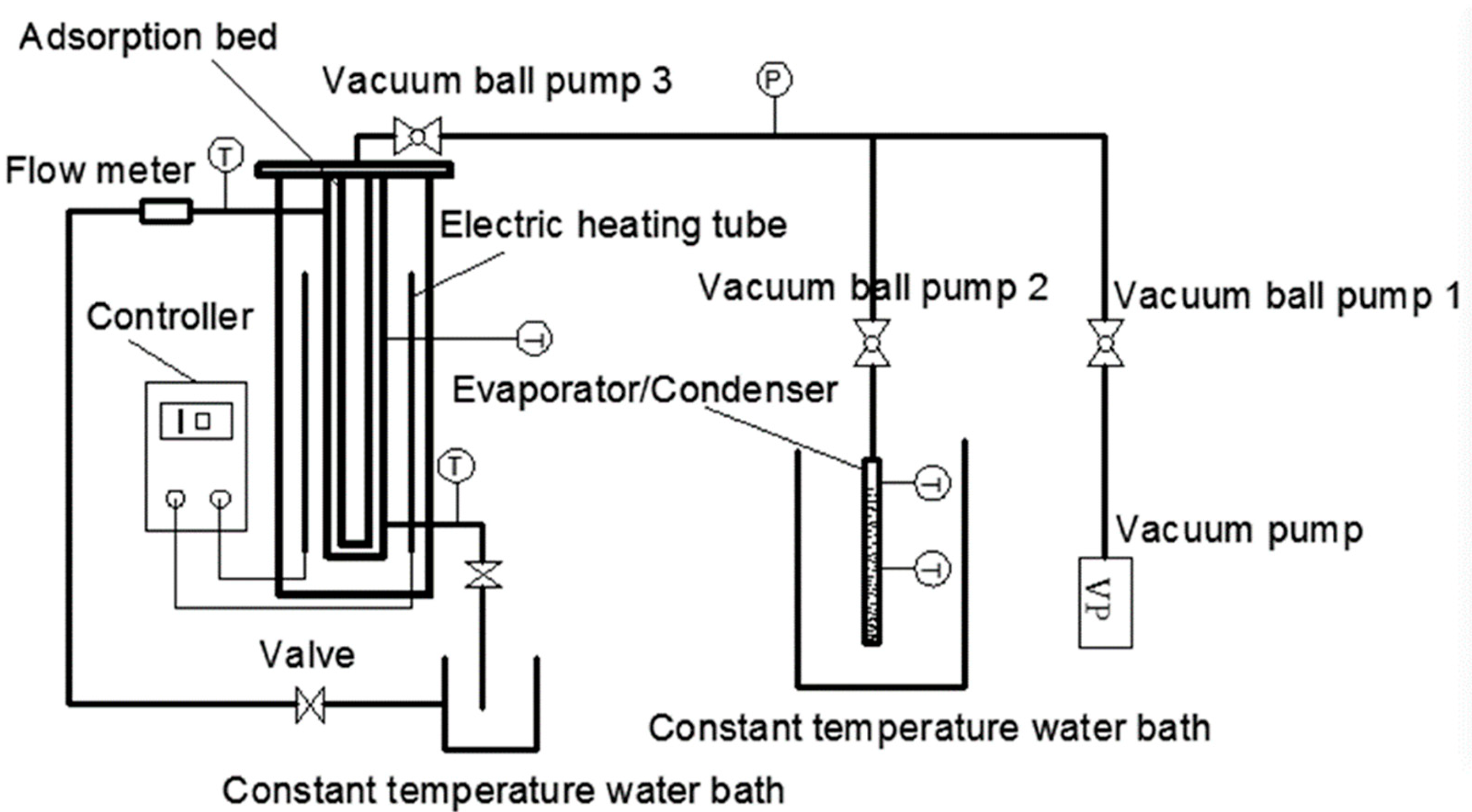
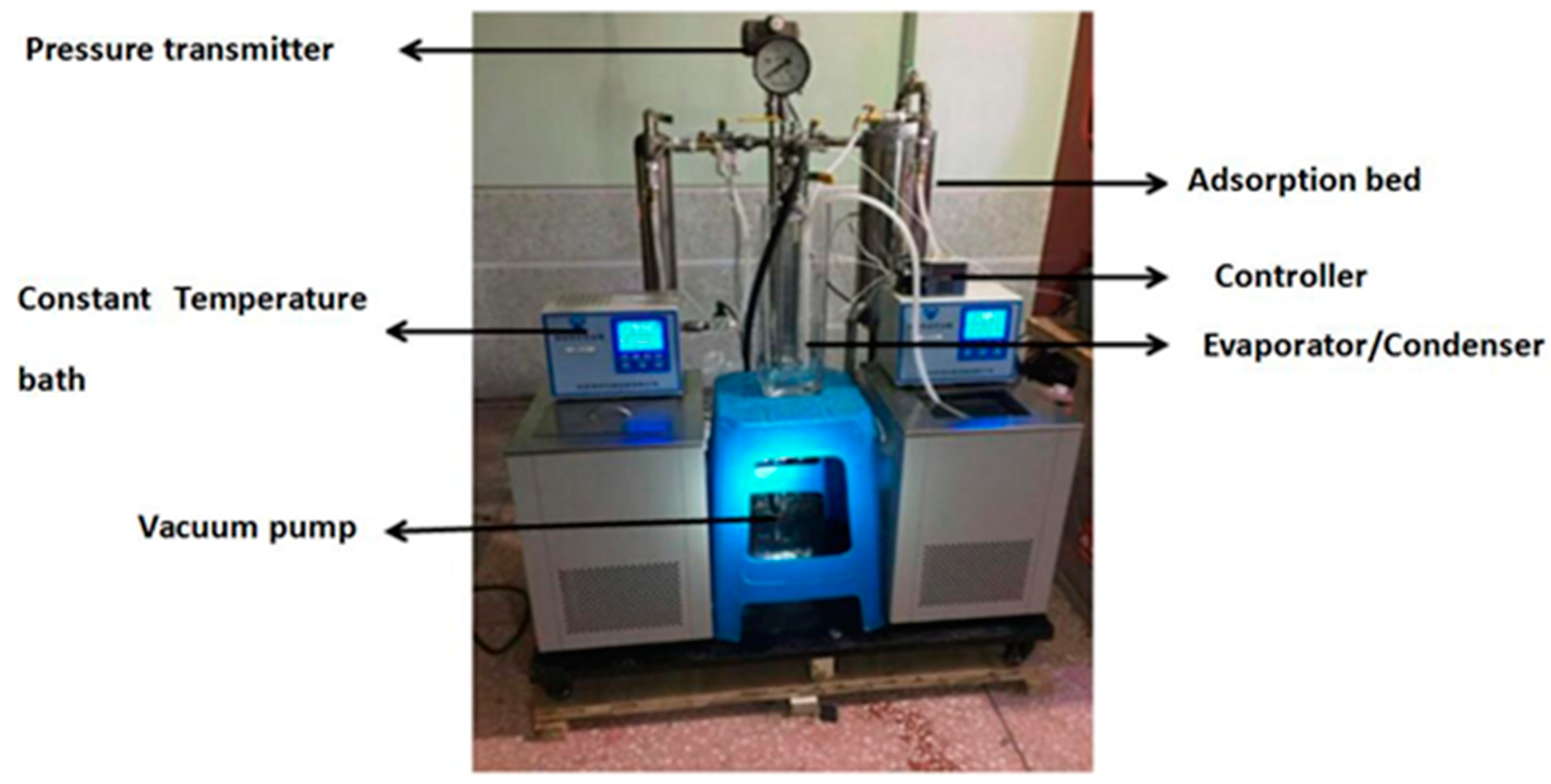
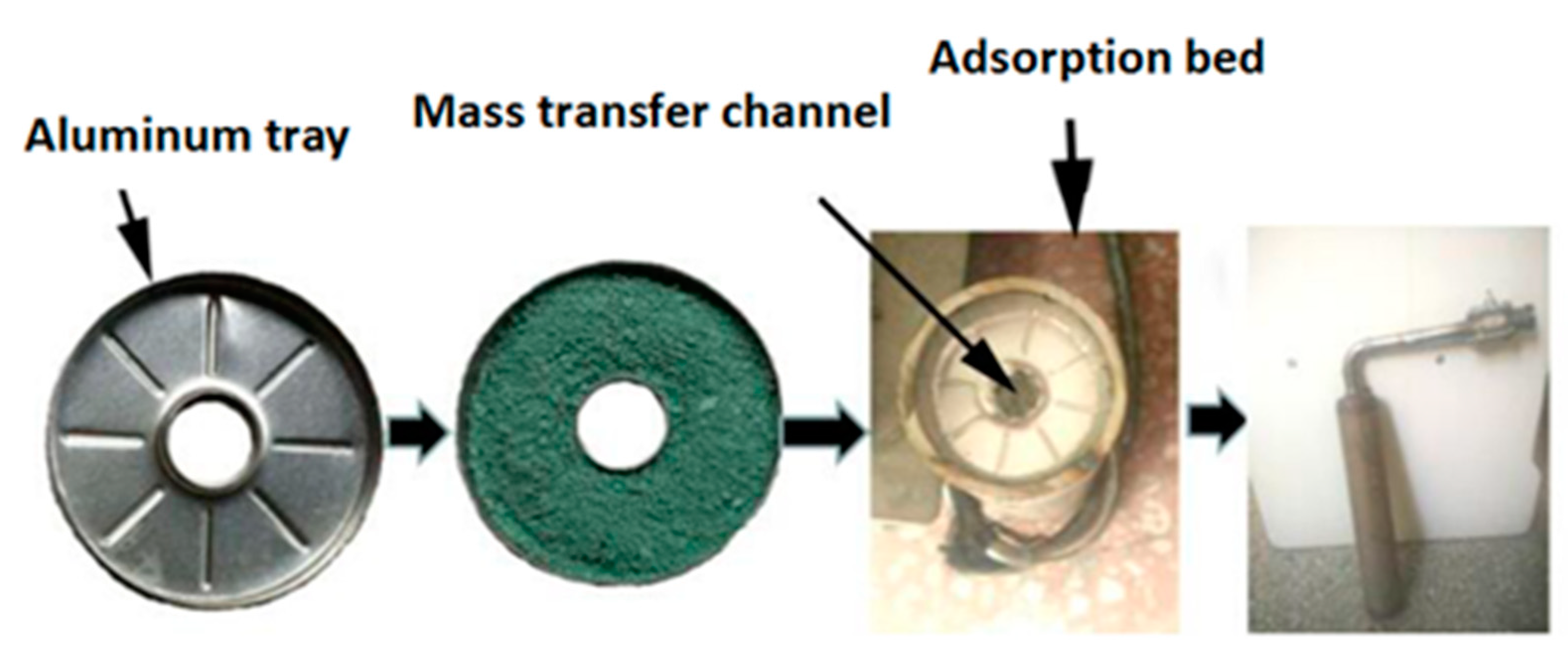
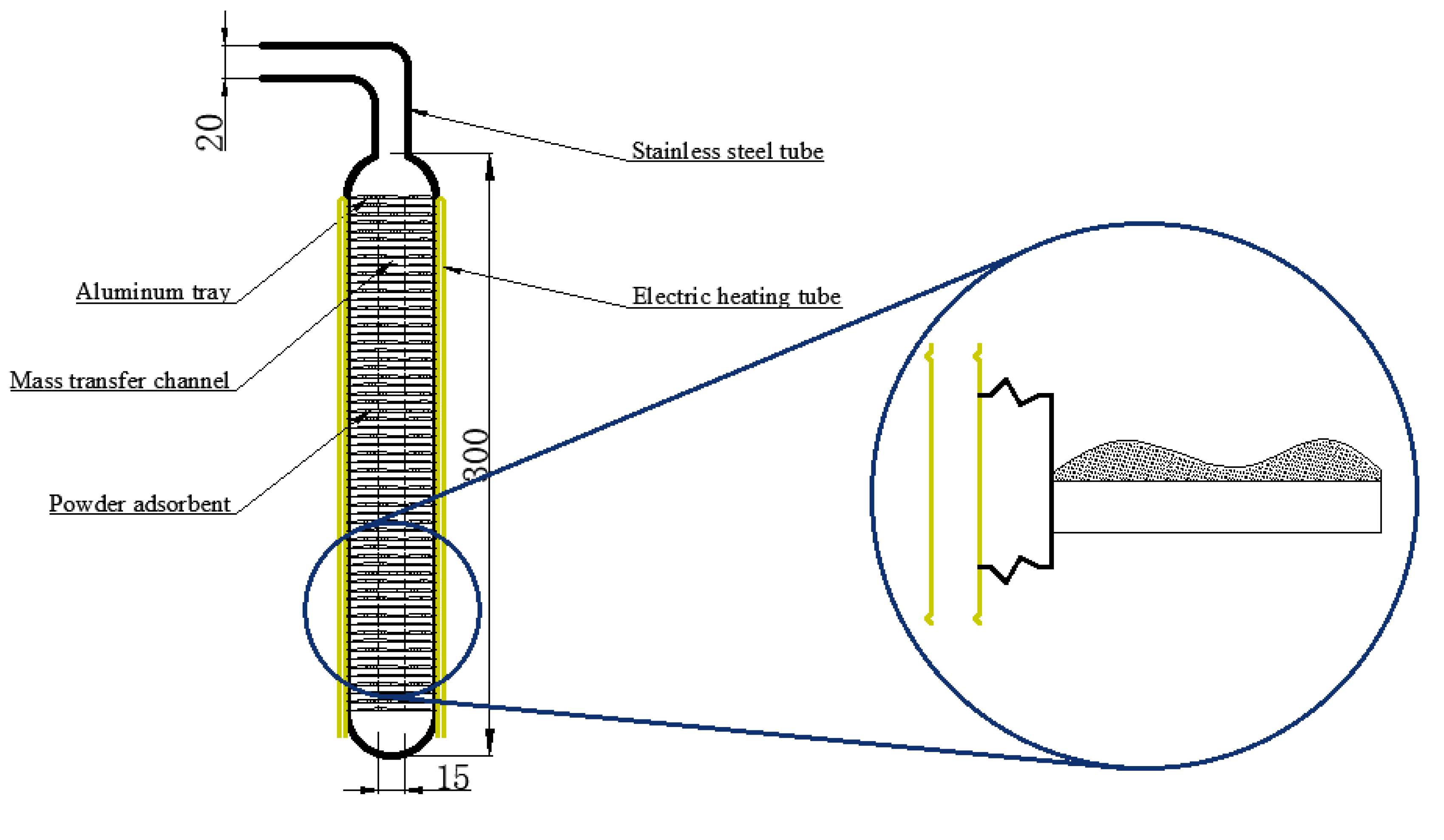
2.4. Experimental Rig of Single-Bed Adsorption System with New Type Adsorbent Filling Method
- (1)
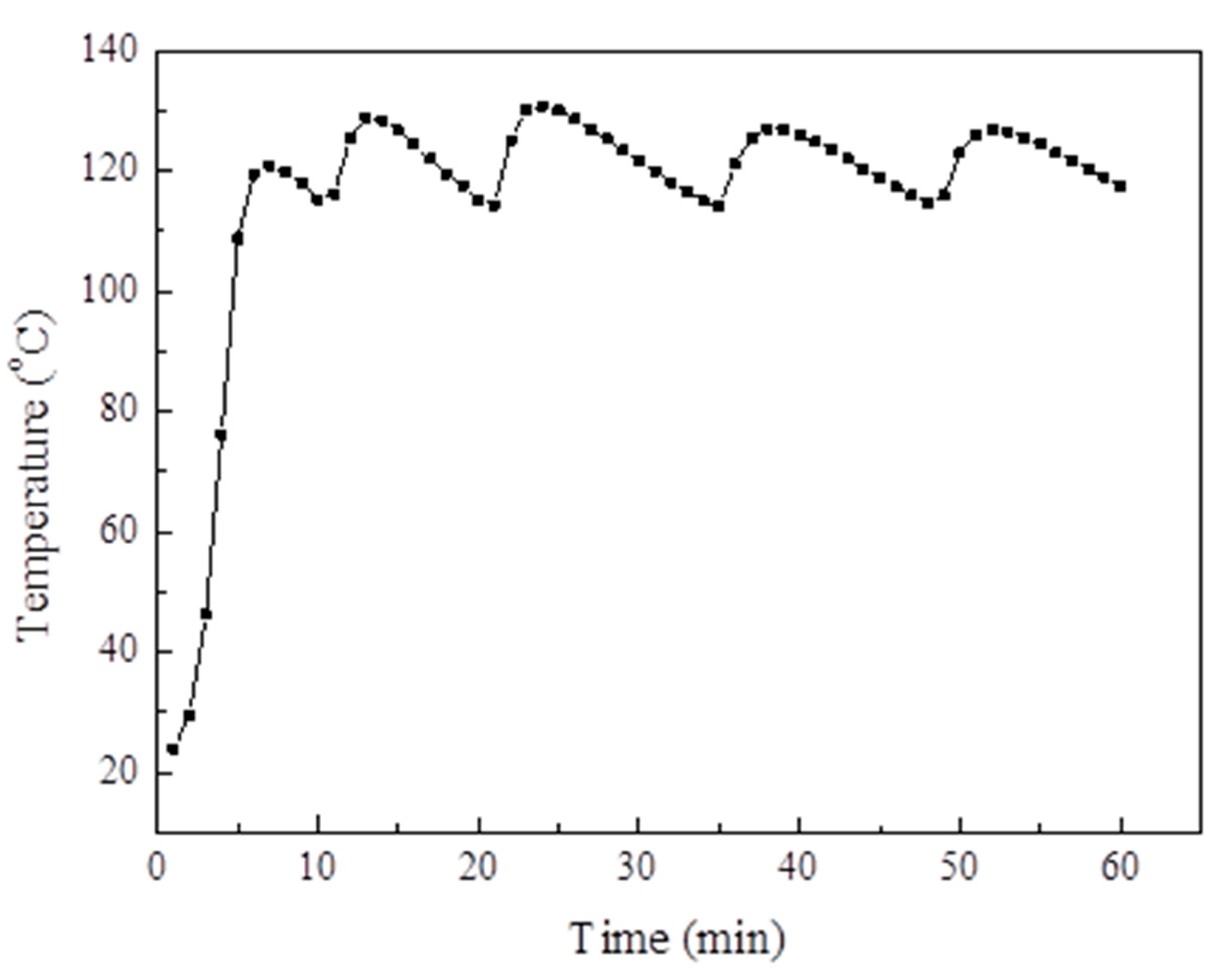
- The adsorption bed was initially heated by the temperature controller, and the adsorption bed temperature reached 120 °C after approximately 10 min. Then, the vacuum pump and vacuum ball valves one and three were opened to heat the adsorption bed. When the pressure of the adsorption bed was close to that of the vacuum, vacuum ball valve three and the electric heating tube were turned off. Finally, the vacuum ball valve two was opened and, while closing the valve and the vacuum pump, the excess air was extracted from the evaporator/condenser until the pressure was the pressure at the evaporation temperature/condensation temperature.
- (2)
- The thermostat tank was set as the corresponding adsorption temperature, the circulating water valve on the left of Figure 1 was opened, then the vacuum ball valve two and three were opened, the adsorption bed and evaporator/condenser could form a closed system. Next, a refrigerant (water) began to evaporate rapidly. Moreover, MIL-101 (Cr) began to absorb the water vapor, the heat released in the adsorption process was taken away by the circulating cooling water. The liquid level of the evaporator at the beginning and end was recorded.
- (3)
- Vacuum ball valves two and three were closed after completing Step (2). Then, the adsorption bed temperature was set to desorption temperature (100 °C) using the temperature controller. The temperature of the constant temperature water bath was set to condensing temperature (30 °C). After 30 min, vacuum ball valves two and three were opened, and the process of desorption–condensation began.
3. Mathematical Model of the Single-Bed Adsorption System
3.1. Basic Assumptions of the Theoretical Model
3.2. Mathematical Model of the Basic Cycle
4. Results and Discussion
4.1. XRD and FTIR Analysis
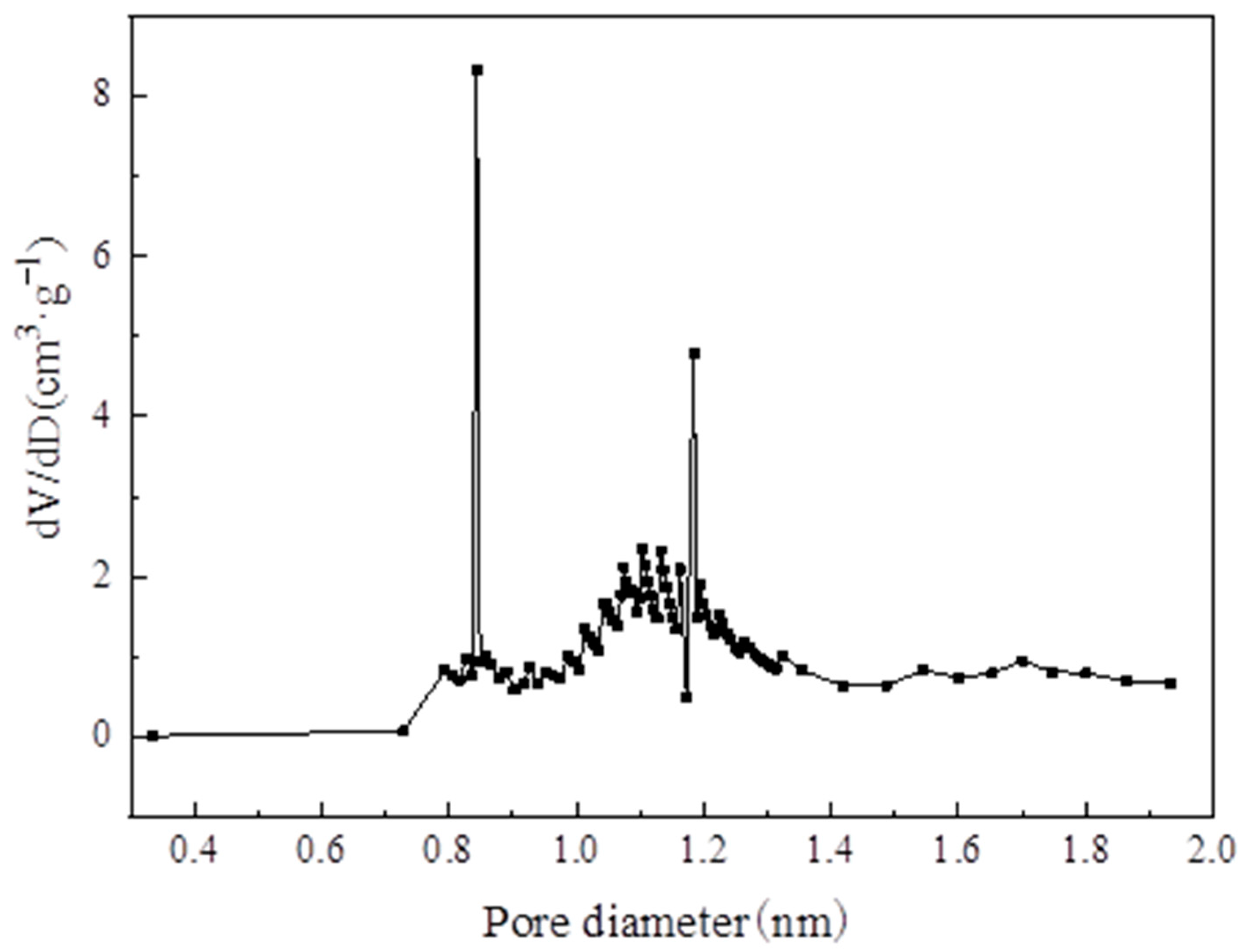
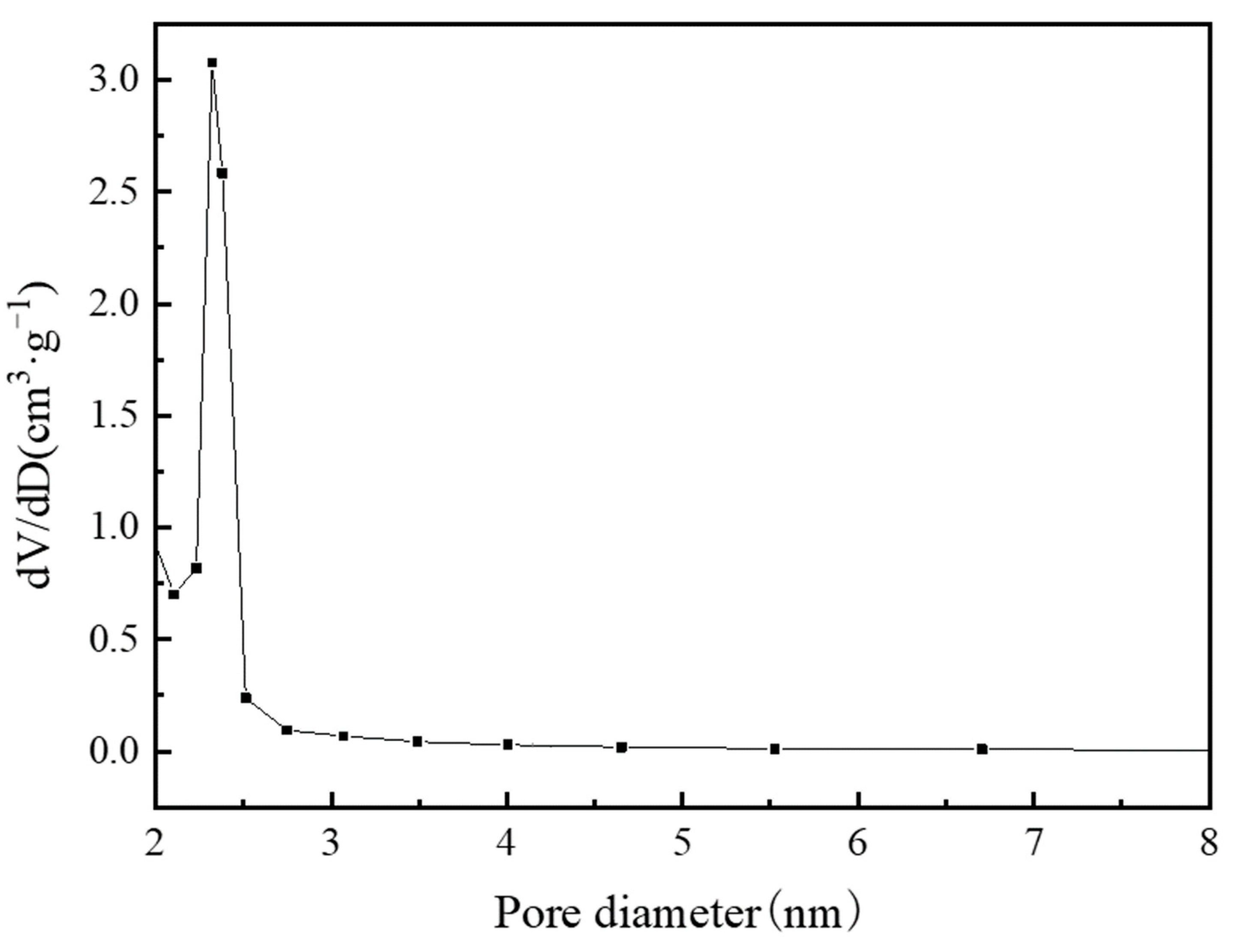
4.2. N2 Adsorption–Desorption Isotherms and Pore Size Analysis
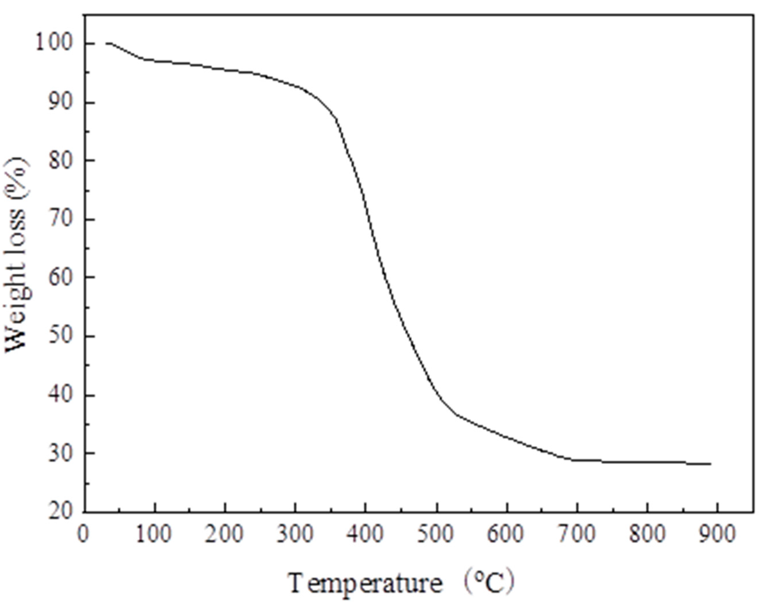
4.3. TGA and SEM Analysis
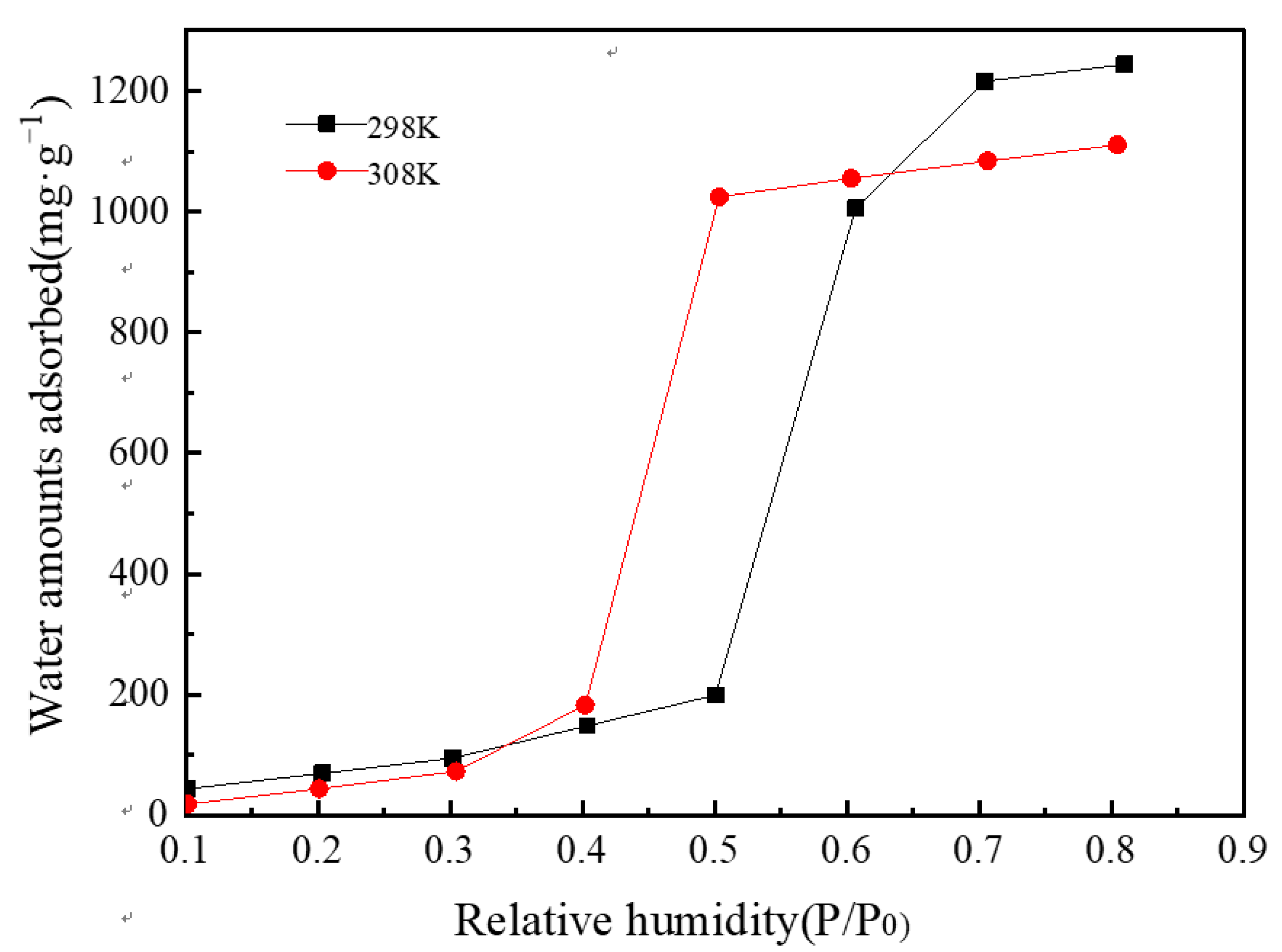
4.4. Water Vapor Adsorption Isotherms
4.5. Analysis of the Simulation Results
4.6. Analysis of the Experimental Results
4.6.1. Changes in Adsorption Bed Temperature and System Pressure During Evacuation
4.6.2. Reliability Results of the Adsorption System
4.6.3. System COP and SCP
5. Conclusions
- (1)
- The XRD (2θ = 3.24°, 5.82°, 8.36°, 9°, 10.24°, and 16.4°) and FTIR spectroscopy results showed that the MIL-101 (Cr) material was successfully synthesized.
- (2)
- The TGA results showed that the synthesized MIL-101(Cr) could be stabilized to 270 °C.
- (3)
- The results of the water vapor adsorption test showed that the maximum water vapor adsorption capacities of MIL-101 (Cr) were approximately 1.2 and 1.1 g·g−1 at 298 and 308 K, respectively.
- (4)
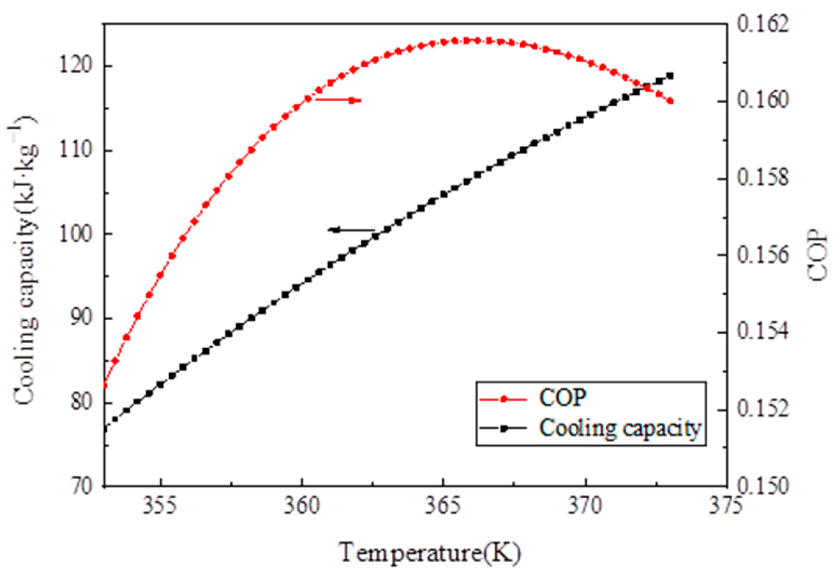
- The simulation results showed that, when the desorption temperature reached 367 K, the system COP reached a maximum value of 0.161 and then decreased with the increase in desorption temperature, whereas the cooling capacity increased with the desorption temperature.
- (5)
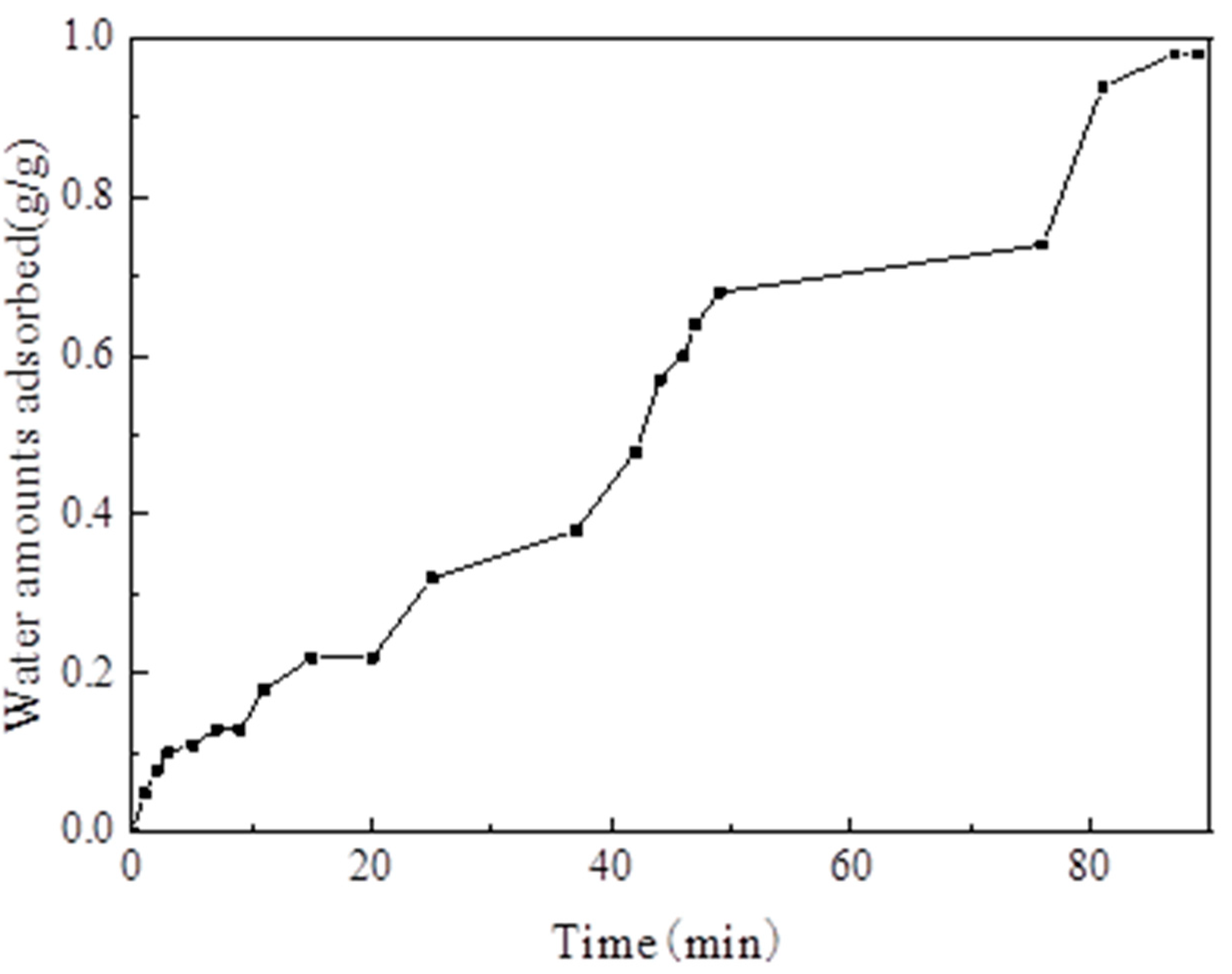
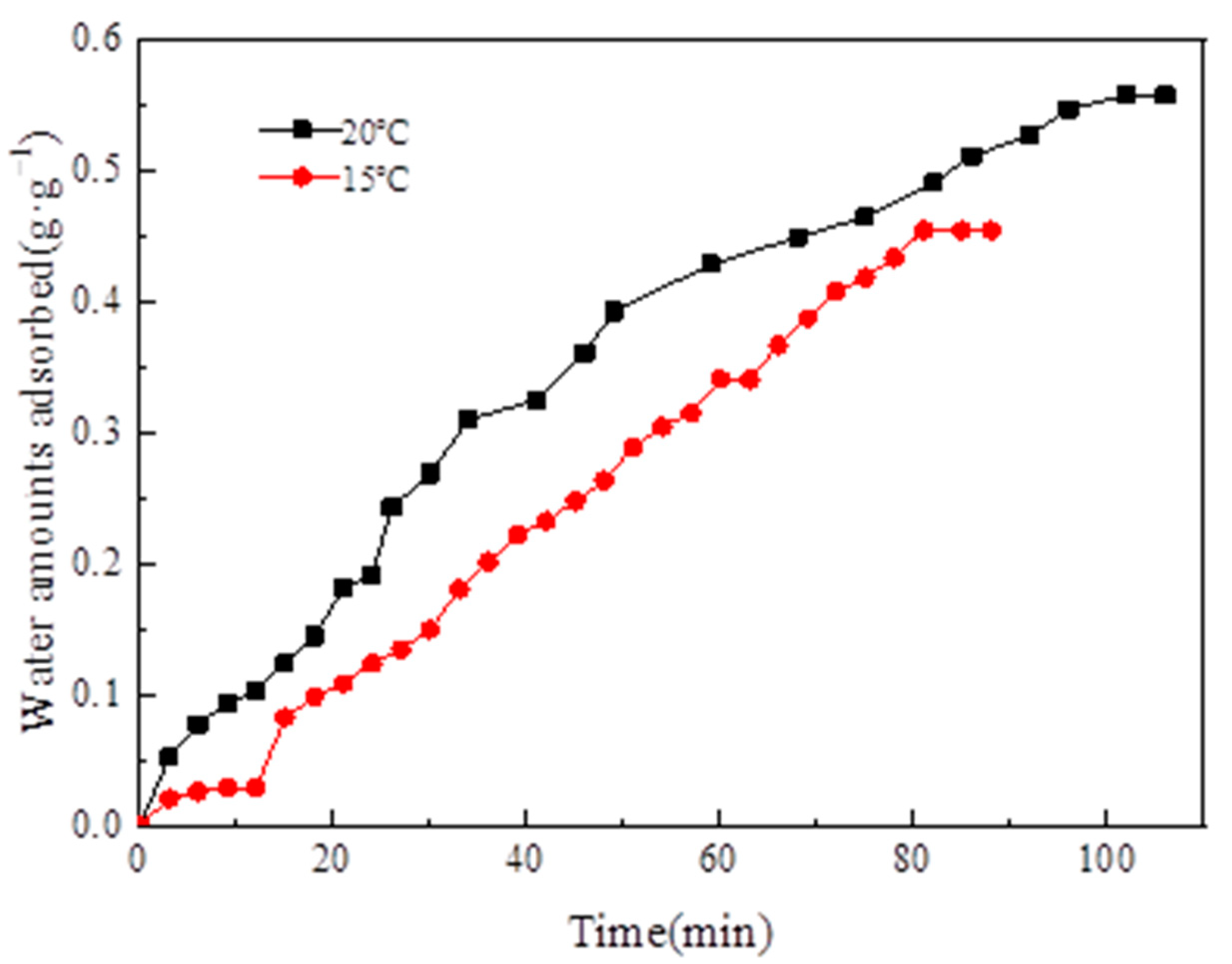
- When the adsorption temperature was 35 °C, the evaporation temperatures were 15 °C and 20 °C, and the amounts of the water vapor equilibrium adsorption of MIL-101 (Cr) were 0.45 and 0.55 g·g−1. Moreover, the SCPs were 42.7 and 43.4 W·kg−1, and the system COPs were 0.112 and 0.144.
Author Contributions
Funding
Acknowledgments
Conflicts of Interest
Nomenclature
| A | Clausius–Claperon equation constant |
| Ca | specific heat capacity of the adsorbent, kJ·kg−1·K−1 |
| Clc | specific heat capacity of water, kJ·kg−1·K−1 |
| Cm | specific heat capacity of stainless steel, kJ·kg−1·K−1 |
| hd | desorption heat, kJ·kg−1·K−1 |
| L | latent heat of vaporization of water, kJ·kg−1 |
| Ma | adsorbent mass, kg |
| Mm | adsorption bed mass, kg |
| Qc | heat taken away during cooling of adsorption bed, kJ·kg−1 |
| Qeva | sensible heat of liquid refrigerant from Tc to evaporation temperature Te, kJ·kg−1 |
| Qg | heat absorbed during the desorption process, kJ·kg−1 |
| Qref | cooling capacity, kJ·kg−1 |
| R | universal gas constant, J·mol−1·K−1 |
| Ta1 | initial adsorption temperature, K |
| Ta2 | adsorption temperature, K |
| Tc | condensation temperature, K |
| Te | evaporation temperature, K |
| Tg1 | initial desorption temperature, K |
| Tg2 | desorption temperature, K |
| Tsat | saturation temperature corresponding to the adsorption pressure, K |
| xconc | water adsorption capacity in gas–solid-phase equilibrium at the time of adsorption in adsorption temperature, kg·kg−1 |
| xdil | water adsorption capacity in gas–solid-phase equilibrium at the time of desorption in desorption temperature, kg·kg−1 |
| x0 | maximum adsorption capacity, kg·kg−1 |
| Δx | circulating adsorption capacity, kg·kg−1 |
References
- Freni, A.; Maggio, G.; Sapienza, A.; Frazzica, A.; Restuccia, G.; Vasta, S. Comparative analysis of promising adsorbent/adsorbate pairs for adsorptive heat pumping, air conditioning and refrigeration. Appl. Therm. Eng. 2016, 104, 85–95. [Google Scholar] [CrossRef]
- Askalany, A.A.; Henninger, S.K.; Ghazy, M.; Saha, B.B. Effect of improving thermal conductivity of the adsorbent on performance of adsorption cooling system. Appl. Therm. Eng. 2017, 110, 695–702. [Google Scholar] [CrossRef]
- Sadeghlu, A.; Yari, M.; Dizaji, H.B. Simulation study of a combined adsorption refrigeration system. Appl. Therm. Eng. 2015, 87, 185–199. [Google Scholar] [CrossRef]
- Schicktanz, M.; Hügenell, P.; Henninger, S. Evaluation of methanol/activated carbons for thermally driven chillers, part II: The energy balance model. Int. J. Refrig. 2012, 35, 554–561. [Google Scholar] [CrossRef]
- Tatlier, M. Performances of MOF vs. zeolite coatings in adsorption cooling applications. Appl. Therm. Eng. 2017, 113, 290–297. [Google Scholar] [CrossRef]
- Banker, N.; Prasad, M.; Dutta, P.; Srinivasan, K. Development and transient performance results of a single stage activated carbon—HFC 134a closed cycle adsorption cooling system. Appl. Therm. Eng. 2010, 30, 1126–1132. [Google Scholar] [CrossRef]
- Kummer, H.; Füldner, G.; Henninger, S.K. Versatile siloxane based adsorbent coatings for fast water adsorption processes in thermally driven chillers and heat pumps. Appl. Therm. Eng. 2015, 85, 1–8. [Google Scholar] [CrossRef]
- Henninger, S.; Schicktanz, M.; Hügenell, P.; Sievers, H.; Henning, H.-M. Evaluation of methanol adsorption on activated carbons for thermally driven chillers part I: Thermophysical characterisation. Int. J. Refrig. 2012, 35, 543–553. [Google Scholar] [CrossRef]
- Jeremias, F.; Zhao, T.; Boldog, I.; Nguyen, B.; Henninger, S.K.; Janiak, C. High-yield, fluoride-free and large-scale synthesis of MIL-101(Cr). Dalton Trans. 2015, 44, 16791–16801. [Google Scholar]
- Küsgens, P.; Rose, M.; Senkovska, I.; Fröde, H.; Henschel, A.; Siegle, S.; Kaskel, S. Characterization of metal-organic frameworks by water adsorption. Microporous Mesoporous Mater. 2009, 120, 325–330. [Google Scholar] [CrossRef]
- Rezk, A.; Al-Dadah, R.; Mahmoud, S.; Elsayed, A. Investigation of Ethanol/metal organic frameworks for low temperature adsorption cooling applications. Appl. Energy 2013, 112, 1025–1031. [Google Scholar] [CrossRef]
- Yan, J.; Yu, Y.; Ma, C.; Xiao, J.; Xia, Q.; Li, Y.; Li, Z. Adsorption isotherms and kinetics of water vapor on novel adsorbents MIL-101(Cr)@GO with super-high capacity. Appl. Therm. Eng. 2015, 84, 118–125. [Google Scholar] [CrossRef]
- Wickenheisser, M.; Jeremias, F.; Henninger, S.K.; Janiak, C. Grafting of hydrophilic ethylene glycols or ethylenediamine on coordinatively unsaturated metal sites in MIL-100(Cr) for improved water adsorption characteristics. Inorg. Chim. Acta 2013, 407, 145–152. [Google Scholar] [CrossRef]
- Liu, Z.; Chen, Y.; Sun, J.; Lang, H.; Gao, W.; Chi, Y. Amine grafting on coordinatively unsaturated metal centers of MIL-101Cr for improved water adsorption characteristics. Inorg. Chem. Acta 2018, 473, 29–36. [Google Scholar] [CrossRef]
- Fröhlich, D.; Henninger, S.K.; Janiak, C. Multicycle water vapor stability of microporous breathing MOF aluminium isophthalate CAU-10-H. Dalton Trans. 2014, 43, 15300–15304. [Google Scholar] [CrossRef] [Green Version]
- Elsayed, E.; Al-Dadah, R.; Mahmoud, S.; Elsayed, A.; Anderson, P.A. Aluminium fumarate and CPO-27(Ni) MOFs: Characterization and thermodynamic analysis for adsorption heat pump applications. Appl. Therm. Eng. 2016, 99, 802–812. [Google Scholar] [CrossRef]
- Jeremias, F.; Lozan, V.; Henninger, S.K.; Janiak, C. Programming MOFs for water sorption: Amino-functionalized MIL-125 and UiO-66 for heat transformation and heat storage applications. Dalton Trans. 2013, 42, 15967–15973. [Google Scholar] [CrossRef]
- Zhao, R.; Deng, S.; Wang, S.; Zhao, L.; Zhang, Y.; Liu, B.; Li, H.; Yu, Z. Thermodynamic research of adsorbent materials on energy efficiency of vacuum-pressure swing adsorption cycle for CO2 capture. Appl. Therm. Eng. 2018, 128, 818–829. [Google Scholar] [CrossRef]
- Kummer, H.; Baumgartner, M.; Hügenell, P.; Fröhlich, D.; Henninger, S.K.; Gläser, R. Thermally driven refrigeration by methanol adsorption on coatings of HKUST-1 and MIL-101(Cr). Appl. Therm. Eng. 2017, 117, 689–697. [Google Scholar] [CrossRef]
- Shi, B.; Al-Dadah, R.; Mahmoud, S.; Elsayed, A.; Elsayed, E. CPO-27(Ni) metal–organic framework based adsorption system for automotive air conditioning. Appl. Therm. Eng. 2016, 106, 325–333. [Google Scholar] [CrossRef]
- Ma, L.; Rui, Z.; Wu, Q.; Yang, H.; Yin, Y.; Liu, Z.; Cui, Q.; Wang, H. Performance evaluation of shaped MIL-101—Ethanol working pair for adsorption refrigeration. Appl. Therm. Eng. 2016, 95, 223–228. [Google Scholar] [CrossRef]
- Henninger, S.; Schmidt, F.; Henning, H.-M. Water adsorption characteristics of novel materials for heat transformation applications. Appl. Therm. Eng. 2010, 30, 1692–1702. [Google Scholar] [CrossRef]
- Teo, H.W.B.; Chakraborty, A.; Kayal, S. Evaluation of CH4 and CO2 adsorption on HKUST-1 and MIL-101(Cr) MOFs employing Monte Carlo simulation and comparison with experimental date. Appl. Therm. Eng. 2017, 110, 891–900. [Google Scholar] [CrossRef]
- Wang, R.Z.; Wang, L.W.; Wu, J.Y. Theory and Its Application of Adsorption Refrigeration; China Science Publishing House: Beijing, China, 2007. [Google Scholar]
- Teng, Y.; Wang, R.; Wu, J. Study of the fundamentals of adsorption systems. Appl. Therm. Eng. 1997, 17, 327–338. [Google Scholar] [CrossRef]


| Content | Value |
|---|---|
| power Supply (V) | 24 |
| operating temperature range (°C) | −30–80 |
| signal (mA) | 4–20 |
| gauge pressure range (kPa) | −100–1600 |
| accuracy (kPa) | 0.1 |
| Symbol | Value | Unit |
|---|---|---|
| Ma | 0.1 | Kg |
| Mm | 2 | Kg |
| Clc | 4.18 | kJ·kg−1·K−1 |
| Cm | 0.5 | kJ·kg−1·K−1 |
| L | 2258 | kJ·kg−1 |
| Specific Surface Area/(m2·g−1) | Pore Volume/(cm3·g−1) | ||
|---|---|---|---|
| BET | Langmuir | ||
| MIL-101(Cr) | 3054 | 4882 | 1.734 |
| Evaporation Temperature (°C) | Adsorption Quantity (g·g−1) | Desorption Quantity (g·g−1) | Cycle Adsorption Quantity (g·g−1) | SCP (W·kg−1) | COP |
|---|---|---|---|---|---|
| 15 | 0.45 | 0.31 | 0.14 | 42.7 | 0.112 |
| 20 | 0.55 | 0.4 | 0.15 | 43.4 | 0.144 |
© 2020 by the authors. Licensee MDPI, Basel, Switzerland. This article is an open access article distributed under the terms and conditions of the Creative Commons Attribution (CC BY) license (http://creativecommons.org/licenses/by/4.0/).
Share and Cite
Liu, Z.; Zhao, B.; Zhu, L.; Lou, F.; Yan, J. Performance of MIL-101(Cr)/Water Working Pair Adsorption Refrigeration System Based on a New Type of Adsorbent Filling Method. Materials 2020, 13, 195. https://doi.org/10.3390/ma13010195
Liu Z, Zhao B, Zhu L, Lou F, Yan J. Performance of MIL-101(Cr)/Water Working Pair Adsorption Refrigeration System Based on a New Type of Adsorbent Filling Method. Materials. 2020; 13(1):195. https://doi.org/10.3390/ma13010195
Chicago/Turabian StyleLiu, Zhongbao, Banghua Zhao, Longqian Zhu, Fengfei Lou, and Jiawen Yan. 2020. "Performance of MIL-101(Cr)/Water Working Pair Adsorption Refrigeration System Based on a New Type of Adsorbent Filling Method" Materials 13, no. 1: 195. https://doi.org/10.3390/ma13010195
APA StyleLiu, Z., Zhao, B., Zhu, L., Lou, F., & Yan, J. (2020). Performance of MIL-101(Cr)/Water Working Pair Adsorption Refrigeration System Based on a New Type of Adsorbent Filling Method. Materials, 13(1), 195. https://doi.org/10.3390/ma13010195