Article

A Novel Optimization Model and Application of Optimal Formula Design for CuxCo1−xFe2O4 Spinel-Based Coating Slurry in Relation to Near and Middle Infrared Radiation Strengthening

1
Department of Mechanical Engineering, Zhejiang Industry Polytechnic College, Shaoxing 312000, China
2
State Key Laboratory of Advanced Metallurgy, University of Science and Technology Beijing, Beijing 100083, China
3
School of Metallurgical and Ecological Engineering, University of Science and Technology Beijing, Beijing 100083, China
*
Author to whom correspondence should be addressed.
Materials 2020, 13(10), 2332; https://doi.org/10.3390/ma13102332
Submission received: 6 April 2020 / Revised: 14 May 2020 / Accepted: 18 May 2020 / Published: 19 May 2020

Abstract

:
Coating slurry, in which the infrared radiation material is the main content, is applied in industrial furnaces to improve heat transfer and raise efficiency of furnaces. In this study, a Cu x Co 1 x Fe 2 O 4 series material with a spinel structure was prepared, and the emissivity of different formulas in two wavebands (3–5 μm and 8–14 μm) was measured. To ensure that the material delivered high emissivity, optimization models were proposed using Matlab software, and proportions of CuO, Co2O3 and Fe2O3 were found to be 16.98%, 16.73% and 66.29%, respectively, in the optimal formula. Thus, using the Cu x Co 1 x Fe 2 O 4 series material and additives, according to mixture regression method, fifteen formulas of coating slurry were designed, prepared and the emissivities were measured. With the Matlab software optimization model, the content of coating slurry was optimized and the corresponding emissivities were measured to be 0.931 and 0.905 in two wavebands, which is in agreement with the optimized calculation.

1. Introduction

Approximately 70% of the energy consumed in China is used in industries, and 25–40% of this energy is used in combustion within industrial furnaces [1]. However, the energy utilization efficiency of furnaces is generally low, and it is therefore important to take measures to improve their performance [2,3,4]. Currently, many technologies have been proposed to raise the efficiency of industrial furnaces, and it has been found that the enhancement of heat transfer in the heating process within furnaces is an efficient way of improving the furnaces’ efficiency [5]. In this respect, an infrared radiation coating was developed and applied to the surface of the inner walls of furnaces, and this is now widely used in industry [6]. The infrared radiation coating enhances the emissivity of the furnaces’ inner wall, and the radiation transfer is thus strengthened between the heated materials and the furnaces’ wall [7]. According to previous industrial practices, the application of infrared radiation coating can raise the efficiency by 5–30% [8].
The energy-saving mechanism of this coating has been the subject of considerable research, and a number of conclusions have been obtained: (a) the coating can improve the emissivity of the wall surface and thus strengthen the radiation heat transfer by absorbing more heat from the incident radiation and by reflecting less [9,10,11]; (b) the coating absorbs the incoming radiation from combustion gases, which have an intermittent spectral distribution, and it then radiates out continuous spectral radiation. It thus enables the heated material to absorb more heat by radiation [12,13,14,15]; (c) the wavelength of the high-temperature radiation within the furnaces is of 1–5 μm, and the coating can improve emissivity in this waveband [16,17,18].
Based on the experimental results, it has been found that ‘doping’ improves emissivity, as it can change the original regular crystalline structure and enable different kinds of ions to occupy the lattice site [19]. For instance, Ying Zhang et al. [20], introduced the RE (RE = La, Ce, Pr, Nd, Sm, Eu, Gd, Tb, and Dy) and Mn ions which are co-doped in Co-Zn ferrites spinel structure by sintering, and a particular higher value of 0.96–0.97 in 8–14 μm emissivity is observed in the RE and Mn co-doped ferrites. Xiaoyan Wu et al. [21], developed the highest infrared emissivity (0.92 ± 0.01) and (0.95 ± 0.01) in 8–14 μm after doping Ce3+ and Y3+ from CoFe2O4 in which the maximum lattice strain (0.341%) and (4.40%) occurred after sintering at 600 ℃. Jian Zhang et al. [22], utilized transition metal ions (Cu2+, Co3+, Ni2+ and Zn2+) to dope and co-dope in Fe3O4 spinel ferrite by sintering process and the results show that the radiation emissivity in 3–5 μm and 8–14 μm can be increased above 0.9 at 600 ℃. These deferent emissivities are mainly determined by the chemical composition and crystal structure of the infrared radiation materials [23]. When the regular structure of the crystal is destroyed by doping with different radii of the ions, the level of the energy transition occurs locally and thus enables the development of infrared radiation [24,25]. In this sense, the infrared radiation coating is generally made as a composite material [26,27,28,29,30,31,32].
According to the different components involved, coatings are classified into: FeO-MnO2 series, Al2O3-SiO2 series, ZrO2 series, CoO series, CrO2 series, cordierite series and SiC series [29,33,34,35,36,37,38,39,40,41]. After conducting research on the different series, researchers have found that materials with spinel structures have higher infrared emissivity than other materials [42,43,44]. Although the theoretical basis for the application of infrared radiation has progressed to date, the composition of the coating still depends on experimentation. It is thus considered that effective methods and theories are required to design a formula for the coating that optimizes its infrared radiation performance. In this paper, a series of Cu x Co 1 x Fe 2 O 4 solid solutions with a spinel structure was developed to effectively improve emissivity [22]. The Cu x Co 1 x Fe 2 O 4 series material with infrared radiation coating was prepared in a laboratory, and the emissivity was then measured. According to the experimental results, we didn’t use mature mathematical prediction models. It should be noted that only the predicted results can be obtained by using these models, but it is not clear which factors affect them. We first determine the weight of the influencing factors, then establish the optimization model, and determine the best formula of spinel material and spinel-based infrared radiation coating.

2. Experimental

Cu x Co 1 x Fe 2 O 4 solid solution was selected for the study as it has a typical spinel structure, and Cu enables the formation of a mixed spinel structure during sintering [45]. The Cu x Co 1 x Fe 2 O 4 were prepared by a sintering process. Analytical grade Co2O3 (99.99%), CuO (99.99%) and Fe2O3 (99.99%) powders were purchased from Shanghai Aladdin Bio-Chem Technology Co., LTD (Shanghai, China)) and used as raw materials to prepare Cu x Co 1 x Fe 2 O 4 . The varying formulas of Cu x Co 1 x Fe 2 O 4 were designed according to different Cu doped ratios (mol%), and the molar content of CuO was regarded as being theoretically proportional to the content of the solid solution [22]. The formula design is shown in Table 1.
Each component was weighed according to the formula weight design in Table 1 and mixed in an agate mortar, and samples were then heat treated under air atmosphere and sintered in a muffle furnace (Shanghai YongWei Furnace Industry Co. LTD, Shanghai, China), according to the temperature control curve of the heat treatment shown in Figure 1.
The samples were heated to 120 °C and kept for 30 min, so that they were fully dry. In order to ensure the reaction was as complete as possible, the samples were heated at 1300 °C for about 4 h and then cooled to 500 °C at a cooling speed of 5 °C/min. Finally, the samples were cooled naturally to room temperature in a muffle furnace. After the sintering process, the samples were ground to powder and those that could pass through a 200 mesh sieve were collected for further study.
In this study, the micromorphology of samples were analyzed after sintering using a scanning electron microscopy (SEM, Instrument model: ZEISS EVO18, Carl Zeiss AG, Heidenheim, Germany). An energy dispersive spectrometer (EDS, Carl Zeiss AG, Heidenheim, German) and an x-ray diffractometer (XRD, Instrument model: AXISULTRADLD, Kratos Analytical Limited, Kyoto, Japan) were used to verify the generation of the Cu x Co 1 x Fe 2 O 4 solid solution. The XRD pattern was measured by X-ray diffractometer with the scan range angle from 10° to 90° at the speed of 10°/min. The emissivity of 3–5 and 8–14 μm band were measured by using a dual-band radiation emissivity measuring meter ((IR-2, Shanghai WangJia Optoelectronic Technology Co., LTD, Shanghai, China). In this paper, the emissivity of each sample in the 3–5 μm and 8–14 μm wavebands has been measured 25 times, and the average emissivity is given.

3. Results

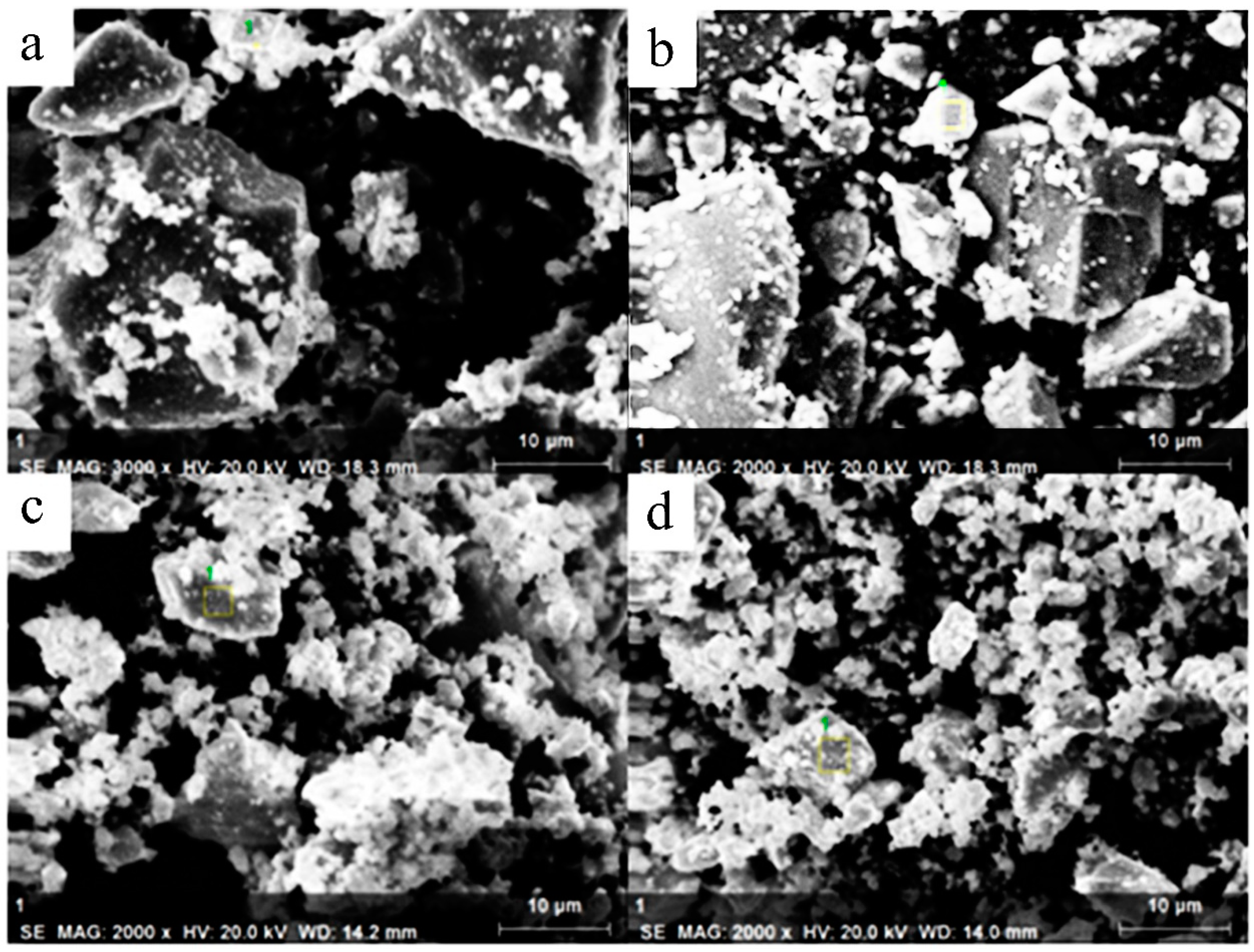
3.1. Morphology of Samples
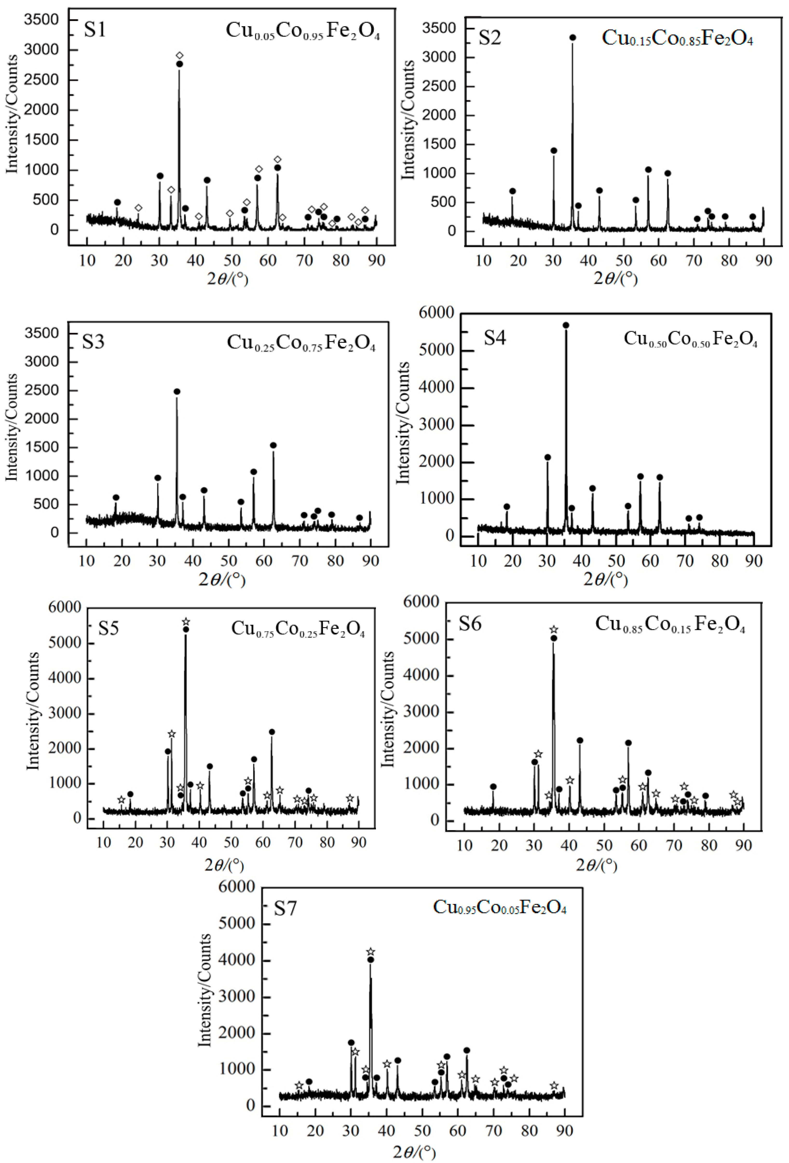
The SEM images of test numbers S2, S3, S5 and S7 in Figure 2 show that the crystal particles of the spinel are irregular polyhedrons. The particles became more irregular with the increased addition of Cu, which may be the result of Cu doping destroying the polarized growth of the spinel crystal. In order to know whether the Cu had been dissolved in the spinel, energy dispersive spectrometer (EDS) analysis was carried out, and the results are shown in Table 2.
As can be seen from Table 2, the values of Cu/(Cu + Co) were 13.9%, 23.7%, 64.97% and 92.8%, which are consistent with the design value of Cu/Co. This illustrates that the Cu had been dissolved in the samples.

3.2. XRD Analysis

The XRD patterns of the samples shown in Figure 3 and we can observe characteristic peaks of spinel structure for samples are in accordance with the Joint Committee Powder Diffraction Standard (PDF# 22-1086). This indicates that the spinel structure was prepared. However, there existed other compositions like Fe2O3 and delafossite (CuFeO2), which are not conducive to the increase of emissivity because they are transparent to infrared radiation [16]. The reason for the presence of Fe2O3 in sample S1 is that improper stoichiometric ratio in the raw materials led to excessive Fe2O3 existed as remnant. On the other hand, in samples S5, S6 and S7, due to excessive CuO in the raw materials, undoped CuFe2O4 tended to be formed, which led to reaction (1) occurred when the temperature was above 1100 °C. Together with reactions (2) and (3) also under high temperature [46], delafossite (CuFeO2) could be formed in corresponding samples.
4 C u F e 2 O 4 4 C u F e O 2 + 2 F e 2 O 3 + O 2
4 C u O 2 C u 2 O + O 2
C u 2 O + F e 2 O 3 2 C u F e O 2
In this sense, the two compositions should be avoided in the process of sintering to eliminating possible adverse effects on infrared radiation performance. Thus, it is necessary to arrange the formula with proper content of raw materials to obtain CuxCo1−xFe2O4 materials for excellent infrared radiation performance.

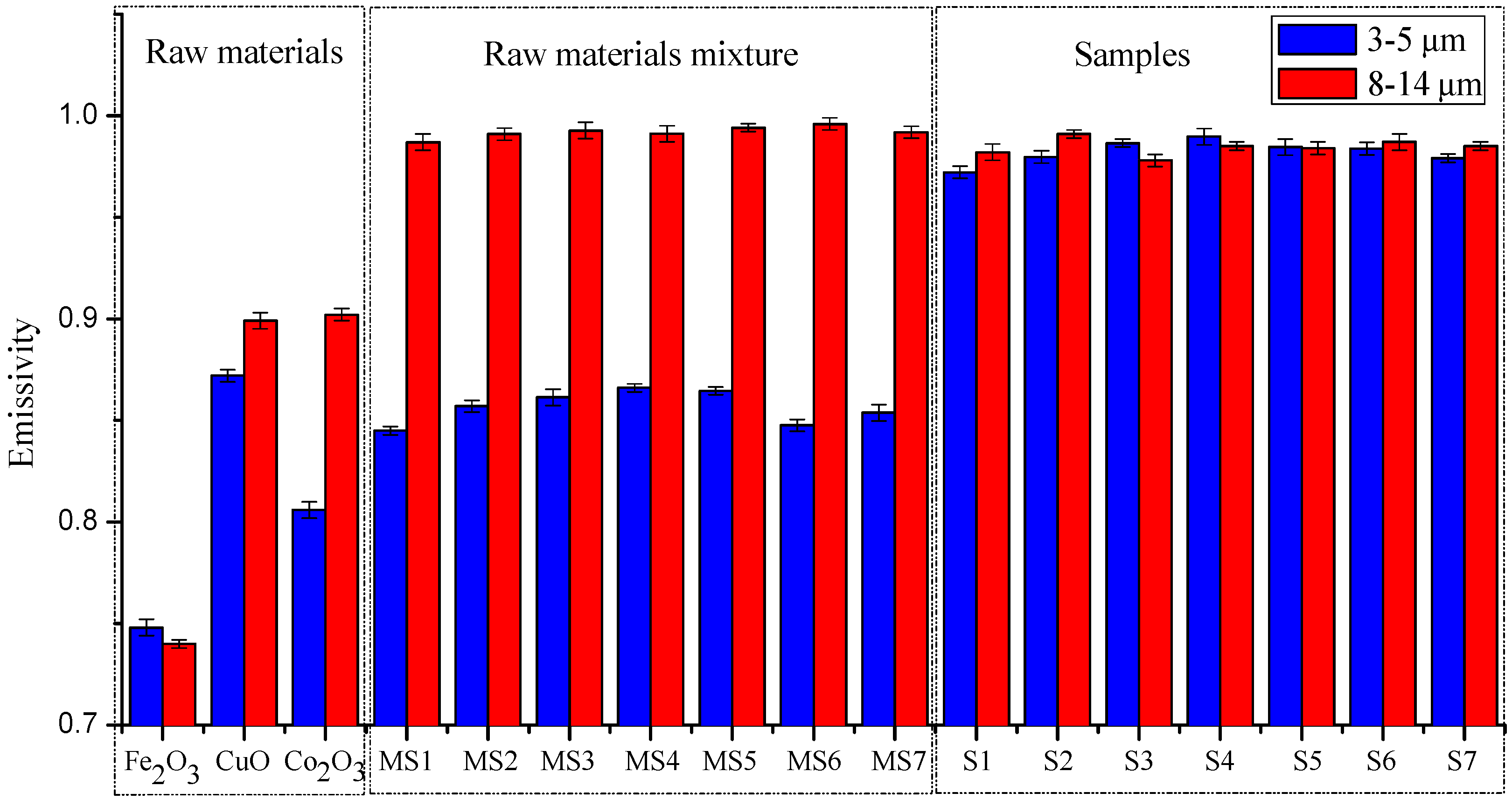
3.3. Strengthening Effect of Emissivity

Owing to the complicated mechanism Cu0.95Co0.05Fe2O4 involved in the emissivity strengthening effect of a solid solution, it is difficult to ascertain whether there is a positive correlation between the emissivity strengthening and the degree of the solid solution. In order to clarify how the solid solution affects the emissivity, the emissivity of two wave ranges (3–5 μm and 8–14 μm) for the spinel-materials of Cu x Co 1 x Fe 2 O 4 solid solution, based on different Cu doped ratios, were measured under 773 K (IR-2 dual band emissivity measurement instrument). Control experiments were conducted in order to validate the emissivity strengthening effect of the ferrite spinel solid solution, in which the emissivity of the chemicals CuO, Co2O3 and Fe2O3 were measured. The results are shown in Figure 4.
The emissivities of CuO, Co2O3 and Fe2O3 were measured, and the average values of emissivity were found to be 0.87, 0.81 and 0.75, respectively, in the 3–5 μm waveband at a temperature of 773 K. In the 8–14 μm waveband, the average values of emissivity were 0.90, 0.90 and 0.74 respectively. In Figure 4, the error bar of all the samples is under ±0.004 which means the accuracy of measured emissivity is believable. Furthermore, the mixing of the three oxides was found to make no contribution to the increase of emissivity in the 3–5 μm waveband, and there was no decrease in the emissivity of samples after sintering in the 8–14 μm waveband. However, samples S1–S7, which were sintered to be the Cu x Co 1 x Fe 2 O 4 solid solution, were found to remarkably increase emissivity, particularly in the waveband of 3–5 μm. It was therefore clarified that the strengthening effect of the ferrite spinel solid solution was effective.
However, although the emissivity seen in Figure 4 was high, the possibility of obtaining an optimal composition for the highest emissivity was considered. Thus, in order to obtain the best emissivity performance for the Cu x Co 1 x Fe 2 O 4 solid solution, or for the coating in where the spinel material is the main composition, it was considered that optimized models, further calculations and analyses were required.

4. Optimization Analysis for Formula Design of Coating Slurry

This study proposes a novel optimization model design for the formula of Cu x Co 1 x Fe 2 O 4 spinel-based coating slurry, with particular consideration for near and middle infrared radiation strengthening. To obtain the best result, the optimization included two steps. The first step was to optimize the Cu x Co 1 x Fe 2 O 4 material, which is then used as the base in the further slurry formula. The second step was to optimize the coating slurry. Both formulas were optimized using the same model, and only the regressions used for the experimental data were different.

4.1. Optimization Model

The purpose of this research was to find an optimal high-emissivity coating for the surface of conventional refractory materials, such as high-aluminum bricks, castable refractories and clay bricks, which generally have low emissivity. It is of note that for widely used refractory materials, emissivity in the waveband of 1–5 μm is much lower than when the wavelength of radiation absorbed or emitted is bigger than 5 μm [47]. Therefore, if an infrared radiation coating with a higher near-infrared waveband emissivity is applied to the surface of the inner furnace, the radiation heat transfer will be strengthened and the furnace efficiency significantly improved [48,49,50,51]. Since the spinel material prepared in this study showed excellent performance in relation to its near-infrared radiation properties, it was therefore considered necessary to develop a high-performance spinel material Cu x Co 1 x Fe 2 O 4 and corresponding coating slurry, using an optimization method that considers the near-infrared radiation property strengthening [52,53,54].
According to Planck’s law, the curve, Eλ-λ, of a graybody’s surface with an emissivity of 0.9 can be obtained at 773 K, as shown in Figure 5. The area below the curve is divided into five parts and indicates the emissive power in the 1–22 μm waveband. The proportion of each part can be obtained using integral computing, and the result is shown in Table 3.
If the emissivity of each waveband is known, the weighted average emissivity in 1–22 μm can be expressed as follows, where the proportional value of each part is the weighting factor:
ε ¯ = 0.13 ε 1 + 0.34 ε 2 + 0.30 ε 3 + 0.18 ε 4 + 0.05 ε 5
For each sample that is based on different formulas, the emissivity, εi, will be different in every waveband, leading to different values of ε ¯ . The radiation ability of blackbody at 3–5 μm and 8–14 μm is the limit state of all high emissivity materials. This means that the radiation ability of materials is smaller than that of blackbody. At the same time, the emissivity ( ε ) is the ratio of E to E b , where E is the radiation ability of materials and E b is the radiation ability of blackbody. In this respect, the radiation ability of CuxCo1−xFe2O4 spinel in 3–5 μm and 8–14 μm is closer to that of blackbody at 3–5 μm and 8–14 μm, the higher the emissivity is in 3–5 μm and 8–14 μm. It thus follows that there must be some relation between the values of ε ¯ and the contents of each formula. The optimization method was therefore designed to obtain the optimal formula by solving the extreme value problem for a maximum value of ε ¯ . The dual-band radiation emissivity measuring meter was used for the measurement of emissivity in wavebands of 3–5 μm and 8–14 μm, and thus, Equation (5) was simplified as follows:
ε ¯ = 0.34 ε 2 + 0.18 ε 4

4.2. Optimization of CuxCo1−xFe2O4 Material

The mole fraction of Cu, expressed as x, is the independent variable function of each waveband’s emissivity. Optimization of the formula was carried out according to the data shown in Figure 3, and the precision is able to meet the demand when the fitted equation is a six-order poly-nominal function. The results of fitting are shown as follows:
ε 2 = 1.5083 × 10 11 x 6 + 4.8166 × 10 9 x 5 5.9452 × 10 7 x 4 + 3.5362 × 10 5 x 3 1.0212 × 10 3 x 2 + 0.012457 x + 0.94118
ε 4 = 4.069 × 10 13 x 6 + 2.4849 × 10 11 x 5 + 9.5818 × 10 9 x 4 1.1785 × 10 6 x 3 + 3.3566 × 10 5 x 2 + 4.6237 × 10 4 x + 0.96899
Using the Matlab software, extreme computing with the objective function based on Equation (5) to obtain the effectual extreme point (the curve seen in Figure 6) delivered the mole fraction of Cu as 51.41%, and the corresponding optimal formula of spinal materials was calculated as shown in Table 4.
After preparing a sample based on the optimal formula, it was tested and the emissivity values are shown in Table 5, where the fitted values are also given for comparison. As shown in Table 5, the fitted and experimental results are in good agreement with each other.

4.3. Optimization of Coating Slurry

The spinel-based infrared radiation coating slurry is composed of Cu x Co 1 x Fe 2 O 4 series material, with the addition of an adhesive, dispersant and thickener [55]. These additives are used to maintain the performance constant of the slurry, but they also affect the emissivity of the coating. Thus, to obtain the optimal formula for the coating slurry with respect to the optimized emissivity, it was considered necessary to study the relation between the components of the slurry and the emissivity.
Water glass (Na2SiO3 and silica), bentonite and sodium hexametaphosphate were selected as the adhesive, dispersant and thickener, respectively. The content of each component, expressed in mass percentage, was determined using a mixture regression design, which included the extreme vertices design, the boundary surface centroid design and the overall centroid design. If the number of factors is p in the mixture regression design, the content of the pth factor can be expressed as xp, and the criteria for the design can be concluded as follows:
{ 0 x i 1   ( i = 1 , 2 , 3 , , p ) x 1 + x 2 + x 3 + + x p = 1
In our design, the variation range of each component’s mass percentage, xi, was obtained based on consulting numerous references, and these are shown as follows:
{   spinel   material   ( x 1 ) : 0.3 x 1 0.6 sodium   hexametaphosphate   ( x 2 ) : 0.05 x 2 0.15   bentonite   ( x 3 ) : 0.15 x 3 0.2   water   glass   ( x 4 ) : 0.3 x 4 0.5
Certain formulas have previously been obtained according to different methods and these are listed in Table 6.
According to Table 5, a total of 15 formulas were prepared in which there were different components in x1, x2, x3 and x4, and 15 types of coating slurry were then made according to the following procedure. Firstly, the adhesive and dispersant were mixed, the thickener was added and the high emissivity materials were then added and mixed. A certain amount of water and anhydrous ethanol were finally added, and after high-speed stirring the high emissivity coating slurry was produced. After the various slurries were coated on the surface of mullite refractory bricks and dried, the samples were then measured for emissivity.
The mathematical model (a quadratic form) used for the regression equation is shown in Equation (10), and it was selected for the mixture design in experiments:
ε ^ = i = 1 p b i x i + i < j b i j x i x j
where bi and bij are the factors to be obtained by regression of the experimental data. The infrared radiation coatings with four components make the p equal four, and thus, Equation (10) can be expressed as follows:
ε ^ = i = 1 4 b i x i + i < j b i j x i x j
Based on the mathematic model and the data of emissivity of each sample (as shown in Table 7), the factors bi and bij in Equation (11) can be defined as the regression of the experiment using SPSS statistical software. In Table 7, y1 and y2 mean that the emissivity of samples in 3–5 μm and 8–14 μm band, respectively.
Based on the data in Table 7, the regression equations were obtained using SPSS statistical software, and the regression equations of 3–5 µm and 8–14 µm can thus be expressed as Equation (12) and Equation (13), respectively:
ε 2 = 8.574 x 2 + 0.087 x 3 2.329 x 4 + 5.234 x 1 x 2 7.255 x 1 x 3 + 1.395 x 1 x 4 + 11.385 x 2 x 3 + 13.991 x 2 x 4 + 2.065 x 3 x 4 + 1.858
ε 4 = 5.892 x 2 + 6.393 x 3 + 0.031 x 4 6.477 x 1 x 2 11.1 x 1 x 3 + 2.738 x 1 x 4 11.828 x 2 x 3 9.493 x 2 x 4 8.49 x 3 x 4 + 0.849
The same method was used in the Cu x Co 1 x Fe 2 O 4 series material optimization, and Equations (12) and (13) can be combined into the objective function, Equation (5). The final regression equation is shown as follows:
ε = 0.34 ε 2 + 0.18 ε 4 = 1.8546 x 2 + 1.18032 x 3 0.78628 x 4 + 0.6137 x 1 x 2 4.4647 x 1 x 3 + 0.96714 x 1 x 4 + 1.74186 x 2 x 3 + 3.0482 x 2 x 4 0.8261 x 3 x 4 + 0.784
The extremum of the equations in the ranges of mass fractions were computed using Matlab software, and the results were: x1 = 30%, x2 = 14.16%, x3 = 20% and x4 = 35.84%. Thus, the emissivities for the 3–5 μm and 8–14 μm wavebands were obtained as 0.944 and 0.901, respectively.
In order to verify the accuracy of the model, the coating was prepared according to the optimal formula, and the emissivity was measured at 773 K. The fitting values and experimental values are shown in Table 8.
Deviations of the fitting values from the experimental values in both the 3–5 μm and 8–14 μm wavebands, were 1.4% and 0.44% respectively, which implies the model is capable of reflecting the relation between emissivity and the components of the slurry.
In summary, the emissivities of the optimal formulas for the Cu x Co 1 x Fe 2 O 4 series material and coatings were compared in both the 3–5 μm and 8–14 μm wavebands and are shown in Table 9.
As can be seen from Table 9, the emissivity of the coating was slightly lower than the emissivity of the materials, but all values were more than 0.9 in both wavebands. In addition, the coating has a good radiation performance in the 3–5 μm waveband at 773 K, which illustrates that the preparation of the coating was successful.

5. Conclusions

In this study, a Cu x Co 1 x Fe 2 O 4 series infrared radiation material with a spinel structure was successfully prepared, and using the Cu x Co 1 x Fe 2 O 4 series material, an adhesive, dispersant and thickener as basic components, 15 formulas were designed for an infrared radiation coating slurry. The coating slurry was then prepared and the emissivity was measured. A model was then constructed and applied to optimize the formulas of both the Cu x Co 1 x Fe 2 O 4 series material and its coating slurry, and verification tests were conducted. Conclusions were obtained as follows:
(1)
The optimal formula for the Cu x Co 1 x Fe 2 O 4 series infrared radiation material was CuO 16.98%, Co2O3 16.73% and Fe2O3 66.29%. At 773 K, the experimental emissivities of the formula were 0.986 and 0.977 in the 3–5 μm and 8–14 μm waveband, respectively.
(2)
Based on the Cu x Co 1 x Fe 2 O 4 series material, a spinel high emissivity coating was prepared and its performance analyzed. In addition, the optimized formula for high emissivity was obtained using the model with Matlab software. The optimal formula obtained was as follows: binder 30%; sodium hexametaphosphate 14.16%; bentonite 20% and water glass 35.84%. At 773 K, the emissivities of the formula were calculated as 0.931 and 0.905 in the 3–5 μm waveband and 8–14 μm waveband, respectively, which are close to the corresponding measured values.
(3)
In this study, the emissivity of the semiconductor with a spinel structure, such as the Cu x Co 1 x Fe 2 O 4 solid solution, in the near and middle infrared wavebands was a key consideration, and this was applied to the optimized process using the model, and as such is confirmed in the experiments.

Author Contributions

Conceptualization, H.D., H.A. and H.B.; methodology, H.A.; software, Y.D.; validation, H.D., H.A. and H.B.; formal analysis, J.Z.; investigation, Y.D. and C.L.; resources, H.D. and Y.D.; data curation, H.D., H.A., J.Z. and H.B.; writing—original draft preparation, H.A.; writing—review and editing, H.D., H.A. and H.B. All authors have read and agreed to the published version of the manuscript.

Funding

The authors gratefully acknowledge financial support from the research funds of the State Key Laboratory of Advanced Metallurgy of China [41603006].

Conflicts of Interest

The authors declare no conflict of interest.

References

  1. Zhu, Q.; Li, X.; Li, F.; Zhou, D. The potential for energy saving and carbon emission reduction in China’s regional industrial sectors. Sci. Total Environ. 2020, 716. [Google Scholar] [CrossRef] [PubMed]
  2. Razdolski, I.; Chen, Y.; Giles, A.J.; Gewinner, S.; Schöllkopf, W.; Hong, M.; Wolf, M.; Giannini, V.; Caldwell, J.D.; Maier, S.A.; et al. Resonant Enhancement of Second-Harmonic Generation in the Mid-Infrared Using Localized Surface Phonon Polaritons in Subdiffractional Nanostructures. Nano Lett. 2016, 16, 6954–6959. [Google Scholar] [CrossRef] [PubMed]
  3. Zhang, B.; Li, J.; Zhang, B.; Chong, R.; Li, R.; Yuan, B.; Lu, S.-M.; Li, C. Selective oxidation of sulfides on Pt/BiVO 4 photocatalyst under visible light irradiation using water as the oxygen source and dioxygen as the electron acceptor. J. Catal. 2015, 332, 95–100. [Google Scholar] [CrossRef]
  4. Zhu, X.; Ruiz, R.; Li, S.; Li, X. An effective heuristic for project scheduling with resource availability cost. Eur. J. Oper. Res. 2017, 257, 746–762. [Google Scholar] [CrossRef]
  5. Zhang, Y.; Wen, D. Relationship between infrared radiation and crystal structure in Fe-Mn-Co-Cu-O spinels. Acta Met. Sin. English Lett. 2008, 21, 15–20. [Google Scholar] [CrossRef]
  6. Liu, F.; Cheng, X.; Mao, J.; Li, Q.; Zeng, X. Effects of rare-earth oxide doping on the thermal radiation performance of HfO2 coating. Ceram. Int. 2019, 45, 13004–13010. [Google Scholar] [CrossRef]
  7. Mao, J.; Ding, S.; Li, Y.; Li, S.; Liu, F.; Zeng, X.; Cheng, X. Preparation and investigation of MoSi2/SiC coating with high infrared emissivity at high temperature. Surf. Coat. Tech. 2019, 358, 873–878. [Google Scholar] [CrossRef]
  8. Zhao, L.Y.; Liu, P.A.; Zeng, F.C.; Liao, Y.F. Preparation and Properties of High Thermal Shock-Resistant Infrared Radiant Energy-Saving Coatings. Jscut 2014, 42, 46–50. [Google Scholar]
  9. Debnath, S.; Das, R. Study of the optical properties of Zn doped Mn spinel ferrite nanocrystals shows multiple emission peaks in the visible range–a promising soft ferrite nanomaterial for deep blue LED. J. Mol. Struct. 2020, 1199. [Google Scholar] [CrossRef]
  10. Hou, L.; Lian, L.; Zhang, L.; Pang, G.; Yuan, C.; Zhang, X. Self-Sacrifice Template Fabrication of Hierarchical Mesoporous Bi-Component-Active ZnO/ZnFe2O4 Sub-Microcubes as Superior Anode Towards High-Performance Lithium-Ion Battery. Adv. Funct. Mater. 2014, 25, 238–246. [Google Scholar] [CrossRef]
  11. Al-Meer, S.; Ghouri, Z.K.; Elsaid, K.; Easa, A.; Al-Qahtani, M.T.; Akhtar, M.S. Engineering of magnetically separable ZnFe2O4@ TiO2 nanofibers for dye-sensitized solar cells and removal of pollutant from water. J. Alloy Compd. 2017, 723, 477–483. [Google Scholar] [CrossRef] [Green Version]
  12. Wang, X.; Zhang, S.; Shao, M.; Huang, J.; Deng, X.; Hou, P.; Xu, X. Fabrication of ZnO/ZnFe2O4 hollow nanocages through metal organic frameworks route with enhanced gas sensing properties. Sens. Actuators B Chem. 2017, 251, 27–33. [Google Scholar] [CrossRef]
  13. Yuan, C.; Cao, H.; Zhu, S.; Hua, H.; Hou, L. Core–shell ZnO/ZnFe2O4@C mesoporous nanospheres with enhanced lithium storage properties towards high-performance Li-ion batteries. J. Mater. Chem. A 2015, 3, 20389–20398. [Google Scholar] [CrossRef]
  14. Lian, L.; Hou, L.; Zhou, L.; Wang, L.; Yuan, C. Rapid low-temperature synthesis of mesoporous nanophase ZnFe2O4 with enhanced lithium storage properties for Li-ion batteries. RSC Adv. 2014, 4, 49212–49218. [Google Scholar] [CrossRef]
  15. Vadiyar, M.M.; Kolekar, S.S.; Chang, J.Y.; Ye, Z.B.; Ghue, A.V. Anchoring ultrafine ZnFe2O4/C nanoparticles on 3D ZnFe2O4 nanoflakes for boosting cycle stability and energy density of flexible asymmetric supercapacitor. ACS Appl. Mater. Interfaces 2017, 9, 26016–26028. [Google Scholar] [CrossRef]
  16. Zhang, J.; Bai, H.; Han, Y.; Wang, F.; He, S.; Liu, P.; Zhang, Z. The effect of CuFe2O4 ferrite phase evolution on 3–5 μm waveband emissivity. Ceram. Int. 2020, 46, 7694–7702. [Google Scholar] [CrossRef]
  17. Wang, S. Effects of Fe on Crystallization and Properties of a New High Infrared Radiance Glass-Ceramics. Environ. Sci. Technol. 2010, 44, 4816–4820. [Google Scholar] [CrossRef]
  18. Cao, H.; Zhu, S.Q.; Yang, C.; Bao, R.Q.; Tong, L.N.; Hou, L.R.; Zhang, X.G.; Yuan, C.Z. Metal-organic-framework-derived two-dimensional ultrathin mesoporous hetero-ZnFe2O4/ZnO nanosheets with enhanced lithium storage properties for Li-ion batteries. Nanotechnology 2016, 27, 46. [Google Scholar] [CrossRef]
  19. Wang, Y.-H.; Liu, Z.-G.; Ouyang, J.-H.; Wang, Y.; Wang, Y. Dependence of the infrared emissivity on SiC content and microstructure of microarc oxidation ceramic coatings formed in Na2SiO3 electrolyte. Appl. Surf. Sci. 2018, 431, 17–23. [Google Scholar] [CrossRef]
  20. Zhang, Y.; Wen, D. Infrared emission properties of RE (RE = La, Ce, Pr, Nd, Sm, Eu, Gd, Tb, and Dy) and Mn co-doped Co0.6Zn0.4Fe2O4 ferrites. Mater. Chem. Phys. 2012, 131, 575–580. [Google Scholar] [CrossRef]
  21. Wu, X.; Yu, H.; Dong, H.; Geng, L. Enhanced infrared radiation properties of CoFe2O4 by single Ce3+-doping with energy-efficient preparation. Ceram. Int. 2014, 40, 5905–5911. [Google Scholar] [CrossRef]
  22. Zhang, J.; Bai, H.; Wei, W.; Ding, Y.; Zhang, X.; Yuan, H.; Zhang, Z. The effect of microstructure on the middle and short waveband emissivity of CuO-doped CuxCo1−xFe2O4 spinel. J. Alloy Compd. 2019, 787, 638–648. [Google Scholar] [CrossRef]
  23. Lu, L.; Fan, X.; Zhang, J.; Hu, X.; Li, G.; Zhang, Z. Evolution of structure and infrared radiation properties for ferrite-based amorphous coating. Appl. Surf. Sci. 2014, 316, 82–87. [Google Scholar] [CrossRef]
  24. Novikov, V.V.; Mitroshenkov, N.V.; Matovnikov, A.V.; Kuznetsov, S. Specific features of the lattice dynamics of CaxSr1−x F2 solid solutions. Mater. Chem. Phys. 2020, 240. [Google Scholar] [CrossRef]
  25. Ye, X.; Zheng, C.; Ma, L.; Huang, X. Microemulsion-assisted hydrothermal preparation and infrared radiation property of TiO2 nanomaterials with tunable morphologies and crystal form. Mater. Sci. Semicond. Process. 2015, 31, 295–301. [Google Scholar] [CrossRef]
  26. Liu, F.; Cheng, X.; Mao, J.; Li, S.; Shao, H.; Liu, T.; Yamaguchi, T.; Zeng, X. Fabrication and characterization of Pr6O11-HfO2 ultra-high temperature infrared radiation coating. J. Eur. Ceram. Soc. 2019, 39, 4208–4215. [Google Scholar] [CrossRef]
  27. Song, K.L.; Xie, M.; Ai, Q.; Yang, L.; Tan, H.P. Effects of size, volume fraction, and orientation of metallic flake particles on infrared radiation characteristics of Al/acrylic resin composite coatings Progress in Organic Coatings. Prog. Org. Coat. 2020, 145. [Google Scholar] [CrossRef]
  28. Tao, X.; Xu, X.; Guo, L.; Hong, W.; Gou, A.; Hou, F.; Liu, J. MoSi2-borosilicate glass coating on fibrous ceramics prepared by in-situ reaction method for infrared radiation Materials & Design. Mater. Des. 2016, 1035, 144–151. [Google Scholar]
  29. Shao, G.; Wu, X.; Kong, Y.; Cui, S.; Shen, X.; Jiao, C.; Jiao, J. Thermal shock behavior and infrared radiation property of integrative insulations consisting of MoSi2/borosilicate glass coating and fibrous ZrO2 ceramic substrate.Surface and Coatings Technology. Surf. Coat. Technol. 2015, 270, 154–163. [Google Scholar] [CrossRef]
  30. Inculet, I.I.; Bergougnou, M. Temperature distribution in an electrostatically applied powder coating layer to be cured with infrared radiation. J. Electrost. 2008, 66, 564–566. [Google Scholar] [CrossRef]
  31. Ding, S.; Mao, J.; Zeng, X.; Cheng, X. Enhanced infrared emission property of NiCr spinel coating doped with MnO2 and rare-earth oxides. Surf. Coatings Technol. 2018, 344, 418–422. [Google Scholar] [CrossRef]
  32. Chuanzhi, S.; Yao, M.; Xv, L.; Xiaoming, W.; Liu, Y.; Jiubin, T. Ring and circular aperture hexagonal array resonance micromesh coating with infrared dual-bandpass extraordinary transmission and strong electromagnetic shielding. Mater. Chem. Phys. 2019, 234, 323–328. [Google Scholar] [CrossRef]
  33. Gan, X.; Xu, D.; Lv, Y. Fabrication of TiO2-coated ZrO2 fibers for heat radiative applications. Mater. Chem. Phys. 2020, 251. [Google Scholar] [CrossRef]
  34. Harb, S.V.; Trentin, A.; Uvida, M.C.; Magnani, M.; Pulcinelli, S.H.; Santilli, C.V.; Hammer, P. A comparative study on PMMA-TiO2 and PMMA-ZrO2 protective coatings. Prog. Org. Coat. 2020, 140. [Google Scholar] [CrossRef]
  35. Stojadinovic, S.; Tadić, N.; Vasilić, R. Down- and up-conversion photoluminescence of ZrO2:Ho3+ and ZrO2:Ho3+/Yb3+ coatings formed by plasma electrolytic oxidation. J. Alloy Compd. 2019, 785, 1222–1232. [Google Scholar] [CrossRef]
  36. Zhang, Z.-Q.; Wang, L.; Zeng, M.-Q.; Zeng, R.-C.; Kannan, M.B.; Lin, C.-G.; Zheng, Y.-F. Biodegradation behavior of micro-arc oxidation coating on magnesium alloy-from a protein perspective. Bioact. Mater. 2020, 5, 398–409. [Google Scholar] [CrossRef]
  37. Wei, G.; Yang, D.; Zhang, T.; Yue, X.; Qiu, F. Fabrication of multifunctional coating with high luminous transmittance, self-cleaning and radiative cooling performances for energy-efficient windows. Sol. Energy Mater. Sol. Cells 2019, 202. [Google Scholar] [CrossRef]
  38. Rahman, M.M.; Jiang, Z.-T.; Yin, C.-Y.; Chuah, L.S.; Lee, H.L.; Amri, A.; Goh, B.-M.; Wood, B.J.; Creagh, C.; Mondinos, N.; et al. Structural Thermal Stability of Graphene Oxide-Doped Copper–Cobalt Oxide Coatings as a Solar Selective Surface. J. Mater. Sci. Technol. 2016, 32, 1179–1191. [Google Scholar] [CrossRef] [Green Version]
  39. He, R.; Li, K.-Z.; Gu, S.; Liu, Q. Comparing ablation properties of NbC and NbC-25 mol.% ZrC coating on SiC-coated C/C composites. Ceram. Int. 2020, 46, 7055–7064. [Google Scholar] [CrossRef]
  40. Wang, F.; Cheng, L.-F.; Xiang, L.; Zhang, Q.; Zhang, L. Effect of SiC coating and heat treatment on the thermal radiation properties of C/SiC composites. J. Eur. Ceram. Soc. 2014, 34, 1667–1672. [Google Scholar] [CrossRef]
  41. Zheng, J.-Q.; Chen, J.; Zhang, B.-H.; Liu, X.-J.; Chen, Z.-M.; Wu, H.-B.; Huang, Z.-R. Electrical percolation and infrared emissivity of pressureless sintered SiC-MoSi2 composites tailored by sintering temperature. J. Eur. Ceram. Soc. 2019, 39, 3981–3987. [Google Scholar] [CrossRef]
  42. Zhang, J.; Fan, X.; Lu, L.; Hu, X.; Li, G. Ferrites based infrared radiation coatings with high emissivity and high thermal shock resistance and their application on energy-saving kettle. Appl. Surf. Sci. 2015, 344, 223–229. [Google Scholar] [CrossRef]
  43. Zhang, X.; Chen, Z.; Wu, C.; Zhang, J.; Wang, F. Solvothermal synthesis of spinel ZnFe2O4 nanoparticles with enhanced infrared radiation property. Chem. Phys. Lett. 2019, 732. [Google Scholar] [CrossRef]
  44. Deng, X.-Q.; Xue, M.-M.; Lv, Y.-L.; Li, R.-H.; Tong, J.-M.; Shi, G.-H.; Yang, Y.; Dong, Y.-C. Study on spectral selective absorbing coatings with spinel structures fabricated via plasma spraying. Vacuum 2020, 174. [Google Scholar] [CrossRef]
  45. Ramakrishna, A.; Murali, N.; Margarette, S.; Samatha, K.; Veeraiah, V. Comparative study of synthesis, structural and magnetic properties of Cu2+ substituted Co-Ni, Co-Zn and Co-Mg nano ferrites. Phys. B Condens. Matter 2018, 530, 251–257. [Google Scholar] [CrossRef]
  46. Li, N.-H.; Lo, S.-L.; Hu, C.-Y.; Hsieh, C.-H.; Chen, C.-L. Stabilization and phase transformation of CuFe2O4 sintered from simulated copper-laden sludge. J. Hazard. Mater. 2011, 190, 597–603. [Google Scholar] [CrossRef] [PubMed]
  47. Jones, J.; Mason, P.; Williams, A. A compilation of data on the radiant emissivity of some materials at high temperatures. J. Energy Inst. 2019, 92, 523–534. [Google Scholar] [CrossRef]
  48. Quandt, N.; Roth, R.; Syrowatka, F.; Steimecke, M.; Ebbinghaus, S.G. Spin-Coating and Characterization of Multiferroic MFe2O4 (M = Co, Ni)/BaTiO3 Bilayers. J. Solid State Chem. 2016, 233, 82–89. [Google Scholar] [CrossRef]
  49. Kalousek, R.; Spousta, J.; Zlámal, J.; Dub, P.; Šikola, T.; Shen, Z.; Salamon, D.; Maca, K. Rapid heating of zirconia nanoparticle-powder compacts by infrared radiation heat transfer. J. Eur. Ceram. Soc. 2017, 37, 1067–1072. [Google Scholar] [CrossRef]
  50. Zhang, J.; Fan, X.; Lu, L.; Hu, X. Plasma sprayed ferrite-based infrared radiation coating directly from transition metal oxides without high-temperature roasting. Mater. Lett. 2015, 161, 348–351. [Google Scholar] [CrossRef]
  51. Del Campo, L.; Pérez-Sáez, R.B.; Tello, M.J. Iron oxidation kinetics study by using infrared spectral emissivity measurements below 570 °C. Corros. Sci. 2008, 50, 194–199. [Google Scholar] [CrossRef]
  52. Castro, C.A.D.O.; Nunes, A.C.P.; Roque, J.V.; Teófilo, R.F.; Santos, O.P.; Santos, G.A.; Gallo, R.; Pantuza, I.B.; Resende, M.D.V. Optimization of Eucalyptus benthamii progeny test based on Near-Infrared Spectroscopy approach and volumetric production. Ind. Crop. Prod. 2019, 141. [Google Scholar] [CrossRef]
  53. Shen, S.; Yuan, Y.; Ruan, Z.; Tan, H. Optimizing the design of an embedded grating polarizer for infrared polarization light field imaging. Results Phys. 2019, 12, 21–31. [Google Scholar] [CrossRef]
  54. Zhang, Y.; Hao, S.; Yu, K.; Cong, M. A new k-interval optimization technique for atmospheric upwelling radiance calculation in infrared absorption bands. J. Quant. Spectrosc. Radiat. Transf. 2015, 160, 75–84. [Google Scholar] [CrossRef]
  55. Li, Z.; Zheng, F.; Gong, H.; Hu, P.; Song, S.; Zhen, Q. Study on ZrSiO4 -aluminosilicate glass coating with high infrared emissivity and anti-oxidation properties. Compos. Commun. 2017, 4, 16–19. [Google Scholar] [CrossRef]
Figure 1. Temperature control curve of heat treatment.
Materials 13 02332 g001
Figure 2. SEM images of samples S2 (a), S3 (b), S5 (c) and S7 (d).
Materials 13 02332 g002
Figure 3. XRD pattern of the sample. The symbols •, ◇ and ☆ represent spinel, Fe2O3 and delafossite, respectively. Cu0.05Co0.95Fe2O4 (S1); Cu0.15Co0.85Fe2O4 (S2); Cu0.25Co0.75Fe2O4 (S3); Cu0.50Co0.50Fe2O4 (S4); Cu0.85Co0.15Fe2O4 (S5); Cu0.95Co0.05Fe2O4 (S6); Cu0.75Co0.25Fe2O4 (S7).
Materials 13 02332 g003
Figure 4. Emissivities of various formulas in 3–5 and 8–14 μm wavebands.
Materials 13 02332 g004
Figure 5. Radiation ability of blackbody and graybody at 773 K.
Materials 13 02332 g005
Figure 6. Curve of optimized objective function of CuxCo1−xFe2O4 materials.
Materials 13 02332 g006
Table 1. Formula for CuxCo1−xFe2O4 solid solution.
Test NumberFormula/gCu Doped Ratio/%
CuOCo2O3Fe2O3
S11.692533.525867.95245
S25.077429.996867.952415
S38.462326.467867.952425
S416.924617.645267.952450
S525.38688.822667.952475
S628.77175.293667.952485
S732.15671.764567.952495
Table 2. EDS result of samples S2, S3, S5 and S7 and the mole ratios of Cu/(Cu + Co).
SamplesThe Mole Fraction of Each Element/%Cu/(Cu + Co)/%
OFeCuCo
S258.1227.282.0412.5713.9
S355.3030.023.4811.2023.7
S556.2431.198.164.4064.97
S745.8137.0215.961.2292.8
Table 3. Proportion of each waveband for blackbody at 773 K.
Waveband1–3 μm3–5 μm5–8 μm8–14 μm14–22 μm
Proportion0.130.340.300.180.05
Table 4. Optimal formula of spinel materials.
CompositionCuOCo2O3Fe2O3
Mass Content/%16.9816.7366.29
Table 5. Experimental values and fitted values of spinel materials.
Waveband3–5 μm8–14 μm
Fitted values0.990.986
Experimental values0.9860.977
Deviation0.41%0.92%
Table 6. Design formula using different design methods.
Numberx1x2x3x4
Extreme Vertices Design10.500.050.150.30
20.300.050.150.50
30.450.050.200.30
40.400.150.150.30
50.350.150.200.30
60.300.050.200.45
70.300.150.150.40
80.300.150.200.35
Boundary Surface Centroid Design90.360.100.180.36
100.300.100.180.42
110.390.050.180.38
120.340.150.180.33
130.380.100.150.37
140.350.100.200.35
Overall Centroid Design150.420.100.180.30
Table 7. Emissivity of each formula.
Numberx1x2x3x4y1y2
10.500.050.150.300.9280.914
20.300.050.150.500.8300.970
30.450.050.200.300.8490.887
40.400.150.150.300.9120.900
50.350.150.200.300.9000.900
60.300.050.200.450.8450.947
70.300.150.150.400.9500.897
80.300.150.150.400.9430.905
90.360.100.180.360.9260.903
100.300.100.180.420.9270.899
110.390.050.180.380.8670.939
120.340.150.180.330.9230.894
130.380.100.150.370.9350.913
140.350.100.200.350.9100.894
150.420.100.180.300.9050.876
Table 8. Fitting values and experimental values.
Waveband3–5 μm8–14 μm
Fitting values0.9440.901
Experimental values0.9310.905
Deviation1.4%0.44%
Table 9. Emissivities of CuxCo1−xFe2O4 series infrared radiation material and coating.
Waveband3–5 μm8–14 μm
Optimal materials0.9860.977
Optimal coating0.9310.905

