Comparative Analysis of Laser and Plasma Surfacing by Nickel-Based Superalloy of Heat Resistant Steel
Abstract
:1. Introduction
2. Experimental
2.1. The Aim of the Study
- Lack of surfacing defects,
- The thickness of a single surfaced layer in range 1–1.5 mm,
- Depth of HAZ ≤ 1.5 mm,
- Relatively high process productivity in comparison with conventional surfacing methods.
- Determination of optimal process parameters range of surfacing based on preliminary technological trials,
- Assessment of geometry change and base material content in the surfaced layer depending on process parameters,
- Comparison of the microstructure of surfaced layer, heat affected zone and base material using metallography,
- Determination of atomic and weight composition of surfaced layers,
- Hardness testing of surfaced layer, heat affected zone and base material,
- Carrying and evaluation out of scratch testing.
2.2. Materials
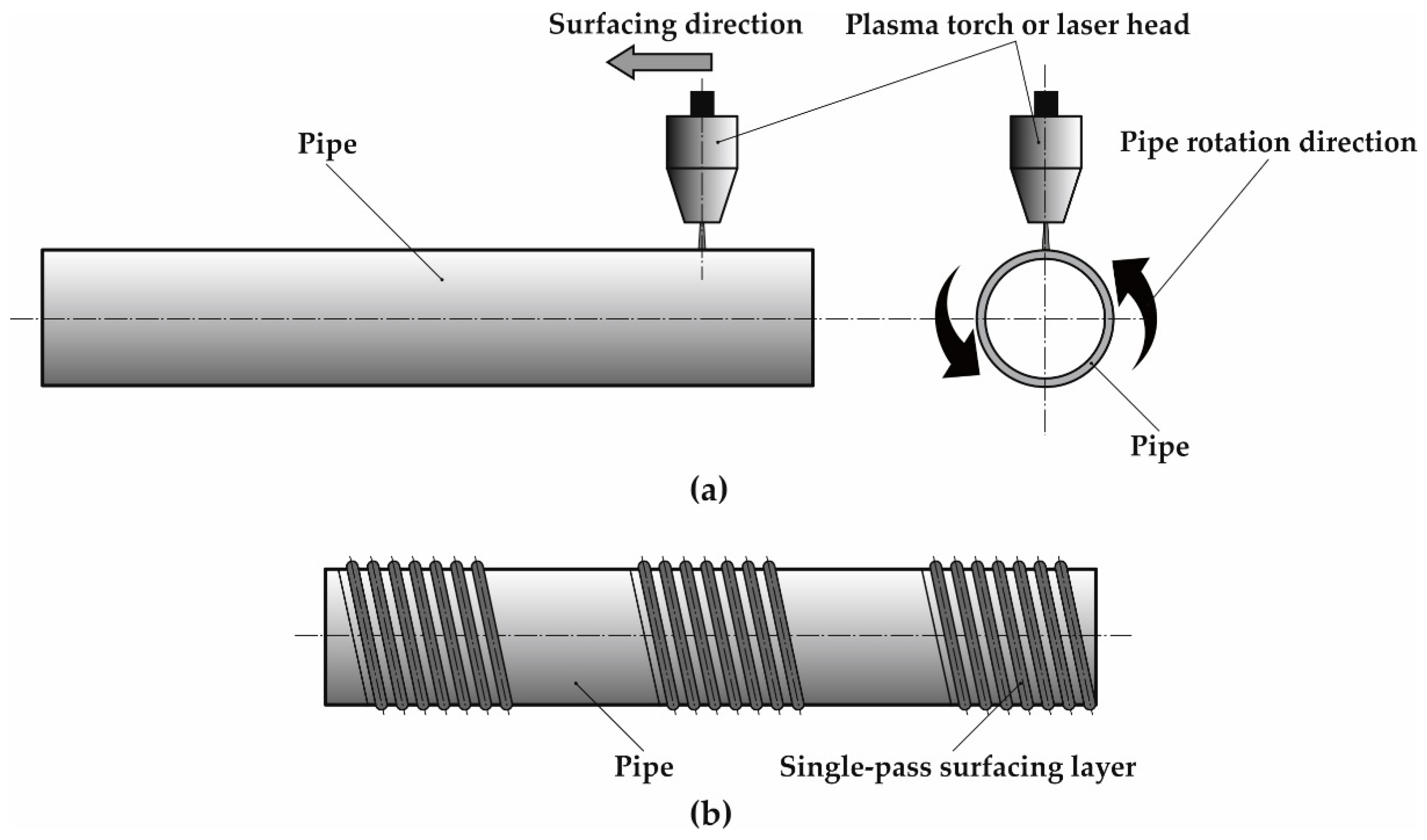
2.3. Plasma Processing
2.4. Laser Processing
2.5. Methodology of Research
2.5.1. Non-Destructive Testing
2.5.2. Metallographic Examination
2.5.3. Hardness Measurements
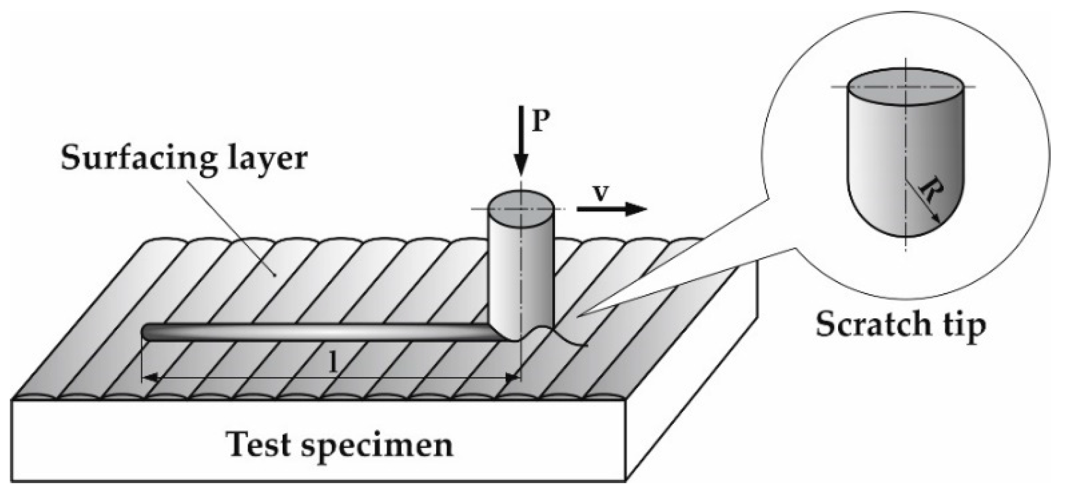
2.5.4. Scratch Test
3. Results and Discussion
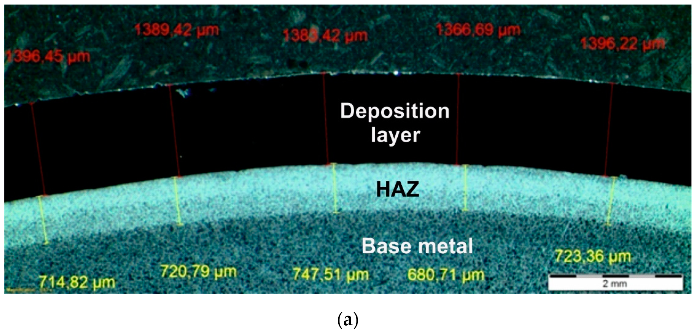
3.1. Non-Destructive Testing Results
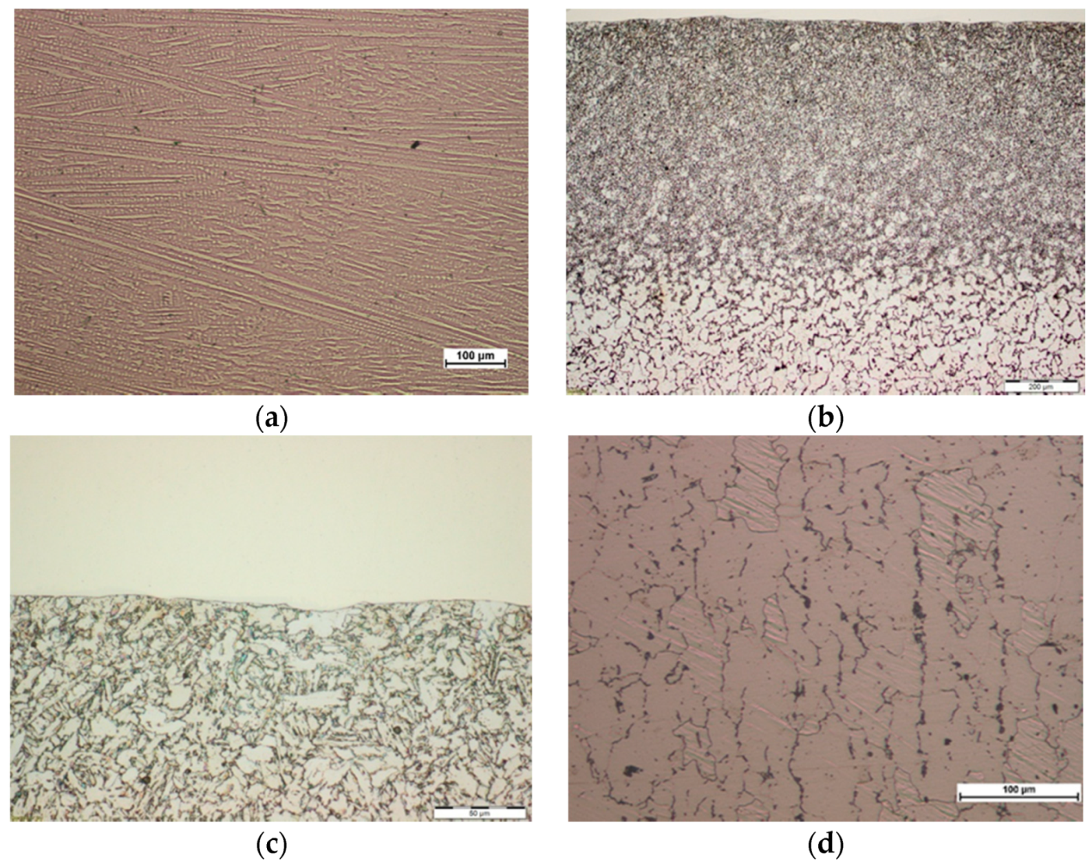
3.2. Metallographic Test Results
3.3. Results of the XRD Analysis
3.4. Hardness Measurements Test Results
3.5. Scratch Test Results
4. Conclusions
- In the case of both powder plasma surfacing and powder laser surfacing narrow parameter range enabling the formation of nickel-based superalloy Inconel 625 layer with dependable fusion into 16Mo3 steel pipe base material, minimal content of base material, iron content on the outer surfaced layer surface under 7 wg.%, and low HAZ depth is present.
- Achieving low base material content in the surfaced layer and reducing detrimental microstructural changes in the base material is possible, even when high surfacing linear energy is used, by application of intensive liquid cooling of inner pipe surface during the process.
- Singular layer depth in case of powder plasma and laser surfacing was two times lower than in the case of MIG surfacing [2,10], moreover finishing machining overmeasure can be reduced in the case of PPTA and HPDDL surfacing. As a result, additional material usage can be reduced in the case of tested technologies.
- In the powder plasma surfaced and powder laser surfaced layers no additional phases, aside from Ni-Si, with lattice parameters close to pure Nickel were found.
- The nickel-based superalloy Inconel 625 surfaced layers manufactured by powder laser surfacing exhibit higher hardness compared to powder plasma surfaced layers.
Author Contributions
Funding
Conflicts of Interest
References
- Dobrzański, J. Materials science interpretation of the life of steels for power plants. Second edition. Open Access Libr. 2016, 3, 1–228. [Google Scholar]
- Golański, G.; Lachowicz, M.; Słania, J.; Jasak, J.; Marszałek, P. Research on 16Mo3 (16M) steel pipes overlaid with Haynes NiCr625 alloy using MIG (131) method. Arch. Metal. Mater. 2015, 60, 2521–2524. [Google Scholar] [CrossRef] [Green Version]
- Węgrzyn, T.; Piwnik, J. Low alloy surfacing with micro-jet cooling. Arch. Metal. Mater. 2012, 57, 540–543. [Google Scholar] [CrossRef]
- Zieliński, A.; Dobrzański, J. Characteristics of changes in properties and structure in X10CrMoVNb9-1 steel due to long-term impact temperatures and stress. Arch. Mater. Sci. Eng. 2013, 60, 72–81. [Google Scholar]
- Uussitalo, M.A.; Vuoristo, P.M.J.; Mantyla, T.A. High temperature corrosion of coatings and boiler steels in reducing chlorine—Containing atmosphere. Surf. Coat. Technol. 2002, 161, 275–285. [Google Scholar] [CrossRef]
- Chmielewski, T.; Golański, D. New method of in-situ fabrication of protective coatings based on Fe-Al intermetallic compounds. Proc. Inst. Mech. Eng. Part B J. Eng. Manuf. 2011, 225, 611–616. [Google Scholar] [CrossRef]
- Adamiec, J. High temperature corrosion of power boiler components surfaced with nickel alloys. Mater. Charact. 2009, 60, 1093–1099. [Google Scholar] [CrossRef]
- Frei, J.; Alexandrov, B.T.; Rethmeier, M. Low heat input gas metal arc surfacing for dissimilar metal weld overlays part I: The heat-affected zone. Surf. World 2016, 60, 459–473. [Google Scholar]
- Frei, J.; Alexandrov, B.T.; Rethmeier, M. Low heat input gas metal arc surfacing for dissimilar metal weld overlays part II: The transition zone. Surf. World 2018, 62, 317–324. [Google Scholar]
- Rozmus-Górnikowska, M.; Blicharski, M.; Kusiński, J. Influence of weld overlaying methods on microstructure and chemical composition of Inconel 625 boiler pipe coatings. Kov. Mater. 2014, 52, 1–7. [Google Scholar] [CrossRef] [Green Version]
- Lippold, J.C.; Kiser, S.D.; DuPont, J.N. Welding Metallurgy and Weldability of Nickel-Base Alloys, 1st ed.; Wiley: Hoboken, NJ, USA, 2011. [Google Scholar]
- Janicki, D. Laser surfacing of Inconel 625-based composite coatings reinforced by porous chromium carbide particles. Opt. Laser Technol. 2017, 94, 6–14. [Google Scholar] [CrossRef]
- Węgrzyn, T.; Miros, M.; Hadryś, D.; Silva, A. Truck frame surfacing reparation by steel covered electrodes with varied amount of Ni and Mo. Transp. Probl. 2010, 5, 87–94. [Google Scholar]
- Lisiecki, A. Tribology and Surface Engineering. Coatings 2019, 9, 663. [Google Scholar] [CrossRef] [Green Version]
- Rajkumar, V.; Arjunan, T.V.; Rajesh Kannan, A. Metallurgical and mechanical investigations of Inconel 625 overlay welds produced by GMAW-hardfacing process on AISI 347 pipes. Mater. Res. Express 2019, 6, 076534. [Google Scholar] [CrossRef]
- Janicki, D.; Musztyfaga-Staszuk, M. Direct Diode Laser Cladding of Inconel 625/WC Composite Coatings. Stroj. Vestn. J. Mech. Eng. 2016, 62, 363–372. [Google Scholar] [CrossRef] [Green Version]
- Tang, B.; Tan, Y.; Zhang, Z.; Xu, T.; Sun, Z.; Li, X. Effects of Process Parameters on Geometrical Characteristics, Microstructure and Tribological Properties of TiB2 Reinforced Inconel 718 Alloy Composite Coatings by Laser Surfacing. Coatings 2020, 10, 76. [Google Scholar] [CrossRef] [Green Version]
- Tomków, J.; Rogalski, G.; Fydrych, D.; Łabanowski, J. Advantages of the application of the temper bead surfacing technique during wet surfacing. Materials 2019, 12, 915. [Google Scholar] [CrossRef] [Green Version]
- Tello, L.; Castejon, L.; Malon, H.; Valladares, D.; Luque, P.; Mantaras, D.A.; Ranz, D.; Cuartero, J. Development of a fatigue life prediction methodology for welded steel semi-trailer components based on a new criterion. Eng. Fail. Anal. 2020, 108, 104268. [Google Scholar] [CrossRef]
- Bayraktar, E.; Jansen, J.P.; Hugele, D.; Kaplan, D. Evaluation of pipeline laser girth weld properties by Charpy (V) toughness and impact tensile tests. J. Mater. Process. Technol. 2004, 147, 155–162. [Google Scholar] [CrossRef]
- Cardoso, J.V.; Gamboa, P.V.; Silva, A. Effect of surface pre-treatment on the behaviour of adhesively-bonded CFRP T-joints. Eng. Fail. Anal. 2019, 104, 1188–1202. [Google Scholar] [CrossRef]
- Janicki, D. Fabrication of high chromium white iron surface layers on ductile cast iron substrate by laser surface alloying. Stroj. Vestn. J. Mech. Eng. 2017, 63, 363–372. [Google Scholar]
- Wang, S.-H.; Yang, C.-W.; Lee, T.-M. Evaluation of Microstructural Features and in Vitro Biocompatibility of Hydrothermally Coated Fluorohydroxyapatite on AZ80 Mg Alloy. Ind. Eng. Chem. Res. 2016, 55, 5207–5215. [Google Scholar] [CrossRef]
- Miraoui, I.; Elimi, E.; Boujelbene, M.; Bayraktar, E. Analysis of Roughness and Microstructure for High-Power Laser Cutting of Stainless Steel. Adv. Sci. Lett. 2013, 19, 483–486. [Google Scholar] [CrossRef]
- Roskosz, S.; Adamiec, J. Methodology of quantitative evaluation of porosity, dendrite arm spacing and grain size in directionally solidified blades made of CMSX-6 nickel alloy. Mater. Charact. 2009, 60, 1120–1126. [Google Scholar] [CrossRef]
- Lisiecki, A. Mechanisms of hardness increase for composite surface layers during laser gas nitriding of the Ti6A14V alloy. Mater. Technol. 2017, 51, 577–583. [Google Scholar]
- Zhou, Z.; Hu, M.-Y.; Xin, H.; Chen, B.; Wang, G.-X. Experimental and theoretical studies on the droplet temperature behavior of R407C two-phase flashing spray. Int. J. Heat Mass Transf. 2019, 136, 664–673. [Google Scholar] [CrossRef]
- Lisiecki, A.; Kurc-Lisiecka, A. Erosion wear resistance of Titanium-Matrix Composite Ti/TiN produced by diode-laser gas nitriding. Mater. Technol. 2017, 51, 29–34. [Google Scholar] [CrossRef]
- Lisiecki, A.; Piwnik, J. Tribological characteristic of titanium alloy surface layers produced by diode laser gas nitriding. Arch. Metall. Mater. 2016, 61, 543–552. [Google Scholar] [CrossRef]
- Zhou, Z.; Wu, W.; Chen, B.; Wang, G.; Guo, L. An experimental study on the spray and thermal characteristics of R134a two-phase flashing spray. Int. J. Heat Mass Transf. 2012, 55, 4460–4468. [Google Scholar]
- Lisiecki, A. Comparison of Titanium Metal Matrix Composite surface layers produced during laser gas nitriding of Ti6Al4V alloy by different types of lasers. Arch. Metall. Mater. 2016, 61, 1777–1783. [Google Scholar] [CrossRef] [Green Version]
- Lisiecki, A. Titanium Matrix Composite Ti/TiN Produced by Diode Laser Gas Nitriding. Metals 2015, 5, 54–69. [Google Scholar] [CrossRef]
- Lisiecki, A. Study of Optical Properties of Surface Layers Produced by Laser Surface Melting and Laser Surface Nitriding of Titanium Alloy. Materials 2019, 12, 3112. [Google Scholar] [CrossRef] [PubMed] [Green Version]
- Lisiecki, A.; Ślizak, D. Hybrid Laser Deposition of Fe-Based Metallic Powder under Cryogenic Conditions. Metals 2020, 10, 190. [Google Scholar] [CrossRef] [Green Version]
- Moskal, G.; Grabowski, A.; Lisiecki, A. Laser remelting of silicide coatings on Mo and TZM alloy. Solid State Phenom. 2015, 226, 121. [Google Scholar] [CrossRef]
- Mikułowski, B. Heat Resistant and High Temperature Creep Resistant Alloys—Superalloys; Publishing House of the AGH University of Technology: Krakow, Poland, 1997. (In Polish) [Google Scholar]
- Adamiec, J.; Kierzak, A. Padding of the components of waste combustion boilers with the use nickel alloys. Mater. Eng. 2008, 4, 380–385. [Google Scholar]
- Cieślak, M.J.; Headley, T.J.; Kollie, T.; Roming, A.D., Jr. A melting and solidification study of Alloy 625. Metall. Trans. A 1988, 19, 2319–2331. [Google Scholar] [CrossRef]
- Cieślak, M.J. The welding and solidification metallurgy of Alloy 625. Weld. J. 1991, 70, 49–56. [Google Scholar]
- Sridhar, R.; Devendranath, R.K.; Arivazhagan, N. Characterization of microstructure, strength and toughness of dissimilar weldments of Inconel 625 and duplex stainless steel SAF 2205. Acta Metall. Sin. (Engl. Lett.) 2014, 27, 1018–1030. [Google Scholar] [CrossRef] [Green Version]
- CEN. Heat Resisting Steels and Nickel Alloys; EN 10095:1999; CEN: Brussels, Belgium, 1999. [Google Scholar]
- CEN. Seamless Steel Tubes for Pressure Purposes—Technical Delivery Conditions—Part 2: Non-Alloy and Alloy Steel Tubes with Specified Elevated Temperature Properties; EN 10216-2; CEN: Brussels, Belgium, 2004. [Google Scholar]
- ISO. Surfacing Consumables—Gases and Gas Mixtures for Fusion Surfacing and Allied Processes; ISO 14175; ISO: Geneva, Switzerland, 2008. [Google Scholar]
- ISO. Non-Destructive Testing of Welds—Visual Testing of Fusion-Welded Joints; ISO 17637; ISO: Geneva, Switzerland, 2016. [Google Scholar]
- ISO. Non-Destructive Testing—Penetrant Testing—Part 2: Testing of Penetrant Materials; ISO 3452; ISO: Geneva, Switzerland, 2013. [Google Scholar]
- ISO. Metallic Materials—Vickers Hardness Test—Part 1: Test Method; ISO 6507; ISO: Geneva, Switzerland, 2018. [Google Scholar]
- Welding—Fusion-Welded Joints in Steel, Nickel, Titanium and Their Alloys (Beam Welding Excluded)—Quality Levels for Imperfections. Available online: https://www.iso.org/standard/54952.html (accessed on 19 May 2020).





| Chemical Composition, wg.% | |||||||||||
|---|---|---|---|---|---|---|---|---|---|---|---|
| C | Si | Mn | P | S | N | Cr | Cu | Mo | Ni | Fe | CE 1) |
| 0.12–0.2 | ≤0.35 | 0.4–0.9 | ≤0.025 | ≤0.01 | ≤0.012 | ≤0.3 | ≤0.3 | 0.25–0.35 | ≤0.3 | Bal. | 0.52 |
| Chemical Composition, wg.% | ||||||||||
|---|---|---|---|---|---|---|---|---|---|---|
| C | Si | Mn | P | S | N | Cr | Cu | Mo | Ni | Fe |
| 0.17 | 0.34 | 0.58 | 0.022 | 0.008 | 0.01 | 0.26 | 0.19 | 0.32 | 0.28 | Bal. |
| Chemical Composition, wg.% | ||||||||||||
|---|---|---|---|---|---|---|---|---|---|---|---|---|
| C | Si | Mn | P | S | Cr | Mo | Co | Ti | Al | Nb+Ta | Fe | Ni |
| ≤0.03 | ≤0.4 | ≤0.5 | ≤0.01 | ≤0.01 | 21–23 | 8–10 | ≤1 | ≤0.4 | ≤0.4 | 3.2–3.8 | ≤5 | Bal. |
| Chemical Composition, wg.% | ||||||||||||
|---|---|---|---|---|---|---|---|---|---|---|---|---|
| C | Si | Mn | P | S | Cr | Mo | Ni | Co | Ti | Al | Nb+Ta 1) | Fe |
| 0.03 | 0.26 | 0.38 | 0.006 | 0.004 | 20.98 | 8.46 | 63.37 | 0.74 | 0.32 | 0.17 | 3.42 | 1.86 |
| Mechanical Properties of Deposit Weld 1) | |||||||
|---|---|---|---|---|---|---|---|
| Hardness, HB 30 | Yield Strength Rp0,2, MPa | Ultimate Tensile Strength Rm, MPa | Elongation A5, % | Maximum Operation Temperature T, °C | Young Modulus E, GPa | Impact Energy ISO-V KV, J | |
| 210 (≤240) | 540 (≥460) | 800 (≥760) | 38 (≥35) | 1000 | 200 (≤209) | +20 °C | –196 °C |
| 160 | 130 (≥32) | ||||||
| Parameters | Sample Designation | ||||||||
|---|---|---|---|---|---|---|---|---|---|
| P1 | P2 | P3 | P4 | P5 | P6 | P7 | P8 | P9 | |
| Surfacing current I, (A) | 160 | 160 | 160 | 170 | 170 | 170 | 190 | 190 | 190 |
| Arc voltage U, (V) | 20 | 20 | 20 | 20 | 20 | 20 | 20 | 20 | 20 |
| Surfacing velocity v 1), (mm/s) | 5.2 | 6.5 | 7.9 | 7.9 | 7.9 | 9.2 | 11.8 | 14.4 | 14.4 |
| Powder feed rate q, (g/min) | 17 | 19 | 17 | 15 | 21 | 21 | 21 | 25 | 27 |
| Plasma gas flow rate Qp 2), (l/min) | 1.5 | 1.5 | 1.5 | 1.5 | 1.5 | 1.5 | 1.5 | 1.5 | 1.5 |
| Shielding gas flow rate Qo 2), (l/min) | 12 | 12 | 12 | 12 | 12 | 12 | 12 | 12 | 12 |
| Transport gas flow rate Qs 2), (l/min) | 4 | 4 | 4 | 4 | 4 | 4 | 4 | 4 | 4 |
| Nozzle-workpiece distance l, (mm) | 5 | 5 | 5 | 5 | 5 | 5 | 5 | 5 | 5 |
| Overlap ratio, (%) | 33 | 33 | 33 | 33 | 33 | 33 | 33 | 33 | 33 |
| Heat input Eu 3), (J/mm) | 642 | 514 | 428 | 455 | 455 | 390 | 339 | 277 | 277 |
| Parameters | Oznaczenie Próbki | ||||||||
|---|---|---|---|---|---|---|---|---|---|
| L1 | L2 | L3 | L4 | L5 | L6 | L7 | L8 | L9 | |
| Laser power, (W) | 1200 | 1400 | 1600 | 1600 | 1000 | 1000 | 1000 | 1000 | 1200 |
| Surfacing velocity 1), (mm/s) | 3.9 | 3.9 | 3.9 | 4.7 | 3.9 | 3.3 | 3.3 | 2.6 | 2.6 |
| Powder feed rate, (g/min) | 10 | 10 | 10 | 15 | 10 | 10 | 7.5 | 5 | 5 |
| Shielding gas flow rate Qo 2), (l/min) | 12 | 12 | 12 | 12 | 12 | 12 | 12 | 12 | 12 |
| Transport gas flow rate Qs 2), (l/min) | 2 | 2 | 2 | 2 | 2 | 2 | 2 | 2 | 2 |
| Overlap ratio, (%) | 33 | 33 | 33 | 33 | 33 | 33 | 33 | 33 | 33 |
| Heat input 3), (J/mm) | 308 | 359 | 410 | 340 | 256 | 303 | 303 | 385 | 462 |
| Sample Designation | P1 1) | P2 | P3 | P4 | P5 | P6 | P7 | P8 | P9 |
|---|---|---|---|---|---|---|---|---|---|
| Average surfacing thickness g, (µm) | 1275 | 1339 | 1269 | 1132 | 1416 | 1193 | 1292 | 1392 | 1646 |
| Average visible HAZ depth s, (µm) | 1252 | 719 | 743 | 795 | 831 | 742 | 715 | 633 | 622 |
| Surfaced layer base metal content 2), U (%) | 10.7 | 5.0 | 3.2 | 4.2 | 3.7 | 5.1 | 4.1 | 4,0 | 3.8 |
| Iron content in surfaced layer 3), Fe (wt. %) | 11.8 | 5.2 | 4.0 | 4.8 | 4.2 | 5.5 | 4.5 | 4.3 | 4.3 |
| Sample Designation | L1 1) | L2 1) | L3 1) | L4 | L5 | L6 | L7 1) | L8 1) | L9 1) |
|---|---|---|---|---|---|---|---|---|---|
| Average surfacing thickness g, (µm) | 610 | 810 | 770 | 1143 | 650 | 1000 | 180 | 260 | 320 |
| Average visible HAZ depth s, (µm) | 1030 | 1128 | 1330 | 841 | 1070 | 1180 | 1120 | 1350 | 1340 |
| Surfaced layer base metal content 2), U (%) | 11.5 | 13.6 | 14.0 | 3.9 | 4.8 | 6.9 | 12.4 | 20.6 | 29.8 |
| Iron content in surfaced layer 3), Fe (wt. %) | 10.4 | 14.9 | 15.1 | 5.1 | 6.8 | 7.5 | 8.9 | 19.1 | 28.7 |
| Microhardness Test Area | Sample Designation | ||||||||
|---|---|---|---|---|---|---|---|---|---|
| P1 | P2 | P3 | P4 | P5 | P6 | P7 | P8 | P9 | |
| Mean Microhardness HV 0.3 | |||||||||
| Base material (16Mo3) | 161.5 | 165.3 | 163.8 | 162.7 | 162.9 | 163.1 | 162.9 | 161.4 | 160.7 |
| Heat affected zone | 209.8 | 193.4 | 196.4 | 199.2 | 190.5 | 186.1 | 182.2 | 180.3 | 178.8 |
| Surfaced layer (Inconel 625) | 242.8 | 245.4 | 241.0 | 246.2 | 248.7 | 249.6 | 242.2 | 245.1 | 242.9 |
| Microhardness Test Area | Sample Designation | ||||||||
|---|---|---|---|---|---|---|---|---|---|
| L1 | L2 | L3 | L4 | L5 | L6 | L7 | L8 | L9 | |
| Mean Microhardness HV0.3 | |||||||||
| Base material (16Mo3) | 163.5 | 166.3 | 168.2 | 161.8 | 160.3 | 164.0 | 163.7 | 160.6 | 163.2 |
| Heat affected zone | 259.5 | 249.7 | 240.5 | 251.2 | 253.7 | 253.0 | 250.5 | 250.7 | 249.9 |
| Surfaced layer | 234.2 | 231.4 | 229.0 | 265.9 | 254.3 | 252.0 | 245.2 | 204.1 | 186.7 |
© 2020 by the authors. Licensee MDPI, Basel, Switzerland. This article is an open access article distributed under the terms and conditions of the Creative Commons Attribution (CC BY) license (http://creativecommons.org/licenses/by/4.0/).
Share and Cite
Czupryński, A.; Wyględacz, B. Comparative Analysis of Laser and Plasma Surfacing by Nickel-Based Superalloy of Heat Resistant Steel. Materials 2020, 13, 2367. https://doi.org/10.3390/ma13102367
Czupryński A, Wyględacz B. Comparative Analysis of Laser and Plasma Surfacing by Nickel-Based Superalloy of Heat Resistant Steel. Materials. 2020; 13(10):2367. https://doi.org/10.3390/ma13102367
Chicago/Turabian StyleCzupryński, Artur, and Bernard Wyględacz. 2020. "Comparative Analysis of Laser and Plasma Surfacing by Nickel-Based Superalloy of Heat Resistant Steel" Materials 13, no. 10: 2367. https://doi.org/10.3390/ma13102367
APA StyleCzupryński, A., & Wyględacz, B. (2020). Comparative Analysis of Laser and Plasma Surfacing by Nickel-Based Superalloy of Heat Resistant Steel. Materials, 13(10), 2367. https://doi.org/10.3390/ma13102367


