Article

Multi-Mode Buckling Analysis of FGM Channel Section Beams

by
Monika Zaczynska
* and
Filip Kazmierczyk
Department of Strength of Materials, Faculty of Mechanical Engineering, Lodz University of Technology, 90-924 Lodz, Poland
*
Author to whom correspondence should be addressed.
Materials 2020, 13(11), 2567; https://doi.org/10.3390/ma13112567
Submission received: 21 April 2020 / Revised: 29 May 2020 / Accepted: 2 June 2020 / Published: 4 June 2020
(This article belongs to the Special Issue Impact Damage and Mechanical Analysis of Thin-Walled Composites)

Abstract

:
The interactive buckling phenomenon in thin-walled channel section beams is investigated in this paper. This study deals with medium length beams made of the step-variable functionally graded materials (FGM) which consists of aluminum and titanium layers. The interaction of local, primary and secondary global buckling mode and their effect on the load-carrying capacity is discussed. The parametric studies are performed to assess the effect of the thickness of the beam’s component, its length and position of the individual layer on the equilibrium paths. Additionally, the influence of the adhesive layer between materials was analyzed. The problem was solved using the Finite Element Method.

1. Introduction

Thin-walled beams are extremely versatile parts used in different branches of industry. Due to the variety of their shapes, they have multiple functions and numerous applications. Elements like guides, girders, or longerons can be made of thin-walled beams. Steel is the most popular material used to form such structures, but nowadays when the optimization of mass becomes more and more important, different materials are used (e.g., composites). GFRP (Glass Fiber Reinforced Polymer) and CFRP (Carbon Fiber Reinforced Polymer) composites are frequently used in the automotive, aerospace, and cycling industry. Due to the orthotropy of such structures, engineers may design the behavior of the detail (i.e., laminate tailoring) based on the working conditions, and therefore parts can be highly optimized. FGM (functionally graded materials) are another type of modern material, which are of interest among researchers due to their huge advantage in providing a smooth change to the mechanical properties through material thickness [1,2]. This gives the possibility to control many parameters, e.g., deformation, dynamic response of FGM structures, and allows the FGM to be tailored for a different application. Thanks to this, FGM structures, e.g., beams, are used in the automotive and aerospace industry as well as in machine elements [3,4,5].
In the worldwide literature, a lot of papers devoted to the problem of stability of FGM structures can be found. Different approaches were applied by various investigators to analyze the loss of the stability phenomenon in FGM members. Analytical, analytical-numerical, and numerical methods are used to examine such structures under various load types. Zhang et al. [6] investigated the thermal buckling of the ceramic–metal structures using the local kriging meshless method based on the local Petrov–Galerkin weak-form formulation and shape functions. Loss of stability under thermal load was also investigated by Babai et al. [7]. The analysis was performed on a functionally graded (FG) porous beam using the third-order shear deformation and physical neutral plane theories. The thermal stability of the FGM plates was analyzed by Do et al. [8,9] with the meshless radial point interpolation method. Zhang et al. [10] investigated the elastoplastic thermal buckling with the symplectic method. Sohn et al. [11] used nine node rectangular elements to investigate the stability of the FGM structure under aero-thermal loads. Moita et al. [12] analyzed FGM and FRP plates under in-plane or thermal load. The instability of FGM plates under thermal load was investigated by Taczala et al. [13]. Prakaash et al. [14] used a shear-deformable finite element method to analyze the FGM plates under in-plane load. In those analyses, the eight-node C0 shear flexible quadrilateral plate elements were applied. An FGM plate subjected to in-plate load was also investigated by Shen [15] who used a semi-analytical approach. Burzynski et al. [16,17] analyzed the stability of FGM structures with the non-linear six-parameter shell theory. Sobhy [18] analyzed the hygrothermal stability of FGM sandwich plates. A new four-variable shear deformation plate theory was introduced in this study. Kumar et al. [19] proposed the new higher-order transverse shear deformation theories (NHSDTs) with five variables to investigate the FGM plate under patch load. Meiche et al. [20] investigated the buckling problem in an FGM sandwich plate using a new hyperbolic shear deformation theory. The problem of loss of stability in FGM beams was investigated in [21,22]. Also, the dynamic buckling in FGM structures is widely investigated by researchers. As an example, the following works can be mentioned: Kiani et al. [23,24,25], Czechowski et al. [26,27,28], Zhang et al. [29,30].
All above presented papers deal with the problem of stability under various load type conditions, such as thermal and mechanical ones. In the world-wise literature, only a few works which are devoted to the problem of the interactive buckling in FGM structures could be found. Kolakowski [31] analyzed the dynamic interactive buckling in trapezoidal FGM beam-columns. Kolakowski and Teter investigated the interactive buckling in thin-walled FGM structures of closed [32] and open [33] cross-sections subjected to the static compression. Kolakowski and Mania [34] analyzed the coupling matrix B effect on the interactive instabilities in FML-FGM (Fiber Metal Laminate–Functionally Graded Material) columns. The interactive buckling in FGM-FML structures was also studied in [35].
It is clear that more studies concerning the problem of the interactive buckling have been devoted to steel structures. As an example, the works of Hung et al. [36], Camotim et al. [37,38,39,40], Niu et al. [41,42] and Kolakowski et al. [43,44] can be mentioned. Camotim et al. [37,38] analyzed the effect of the interaction of the local flexural, distortional and global buckling modes on the structure response. Niu et al. [41,42] investigated the distortional-global interaction buckling observed in results of performed experimental and the numerical tests. The analysis was carried out on channel section steel beams where the elastic-plastic model of the material was assumed. Kolakowski [43] developed a Semi Analytical Method (SAM) based on Koiter’s theory which enables analysis of non-linear instabilities from global to local through their interaction. In [44], SAM was used to analyze the influence of the secondary buckling mode on post-buckling behavior of channel section steel beams. Further investigations are shown in the paper [45], where the influence of the beam length on the interactive buckling was analyzed. The secondary global buckling mode was considered, and the most dangerous interval of beam lengths was defined. The verification of SAM using the finite element method (FEM) was performed for steel [46] and FRP (Fiber Reinforced Polymer) [47] beams for the most dangerous beam lengths interval [45]. In the paper [46], analysis of the interaction of buckling modes on the post-buckling behaviour is presented, and modes with the ratio of the critical load for the primary global to local mode around 0.75 and secondary global to primary one around 10 were considered. In the paper [47], ratios of the considered bifurcation loads were in the interval 0.6–1.4 and 4–12.
The strongest influence of the different buckling mode interaction can be noticed when the ratio of the primary global mode to the local one is in the interval of 0.8–1.2, which has been proved in papers [32,33,34,35,37,38,41,42,43,44,45,46]. It was decided to analyze wider range of ratios and it is 2.6–4.3 for primary global mode to local one and 4–12 for secondary mode to primary one.
The authors of this paper paid special attention to the problem of the interactive buckling in the FGM beams subjected to pure bending. Parametric studies were performed to analyze the influence of the beam wall thickness, the volume percentage of the beam’s components and the location of the aluminum and titanium layers (inside or outside) on the post-buckling behavior. Two various lengths of the beam were considered. Moreover, it was decided to investigate the effect of the adhesive layer present between constituent materials.

2. Materials and Methods

Numerical analyses were performed using the finite element method (ANSYS APDL software) [48]. Thin-walled channel section beams with the geometry description presented in Figure 1, and their values given in Table 1, were taken into consideration. Beams composed of aluminum Al and titanium Ti sheets with a different thickness of each component (tAl and tTi) were analyzed. The influence of the adhesive layer between aluminum and titanium sheets was taken into account. Two different total walls thickness t = 1 mm (or with adhesive layer t = 1.1 mm) and t = 2 mm (or with adhesive layer t = 2.1 mm) as well as two variants A (aluminum sheet outside) and B (aluminum sheet inside) were studied. The lengths of the beams were chosen, based on the signature curve (Figure 2), to obtain the highest influence of the secondary global buckling mode.
The signature curve presents the critical buckling load in the function of half-wavelength in the longitudinal direction of the beam. Figure 2 presents the curve for the exemplary FGM beam. The lower curve refers to the lowest values of the buckling mode, while the upper one corresponds to the similar beams’ behavior but under higher values of the critical load. Kolakowski and Jankowski [44,45] found out that the highest influence of the secondary buckling mode is observed for the medium-length beams where the range of half-wave length is located on the decreasing upper signature curve (denoted as secondary buckling mode in Figure 2). Thus, based on these works [44,45], the medium-length beams with the length L = 300 mm and L = 400 mm were chosen. Table 2 summarizes the analyzed samples and Table 3 shows mechanical properties of FGM beam components. It was assumed that the materials, from which the beams are made, obey Hooke‘s law. Many samples were taken into consideration, which differs in:
  • The location of the aluminum and titanium layer (variant A and B),
  • The thickness of aluminium and titanium sheet (tAl/tTi = 1/3, tAl/tTi = 1 and tAl/tTi = 3),
  • The existence of adhesive layer tAd (samples with and without an adhesive layer—tAd = 0 or tAd = 0.1 mm),
  • The length of the beam (L = 300 mm and L = 400 mm).
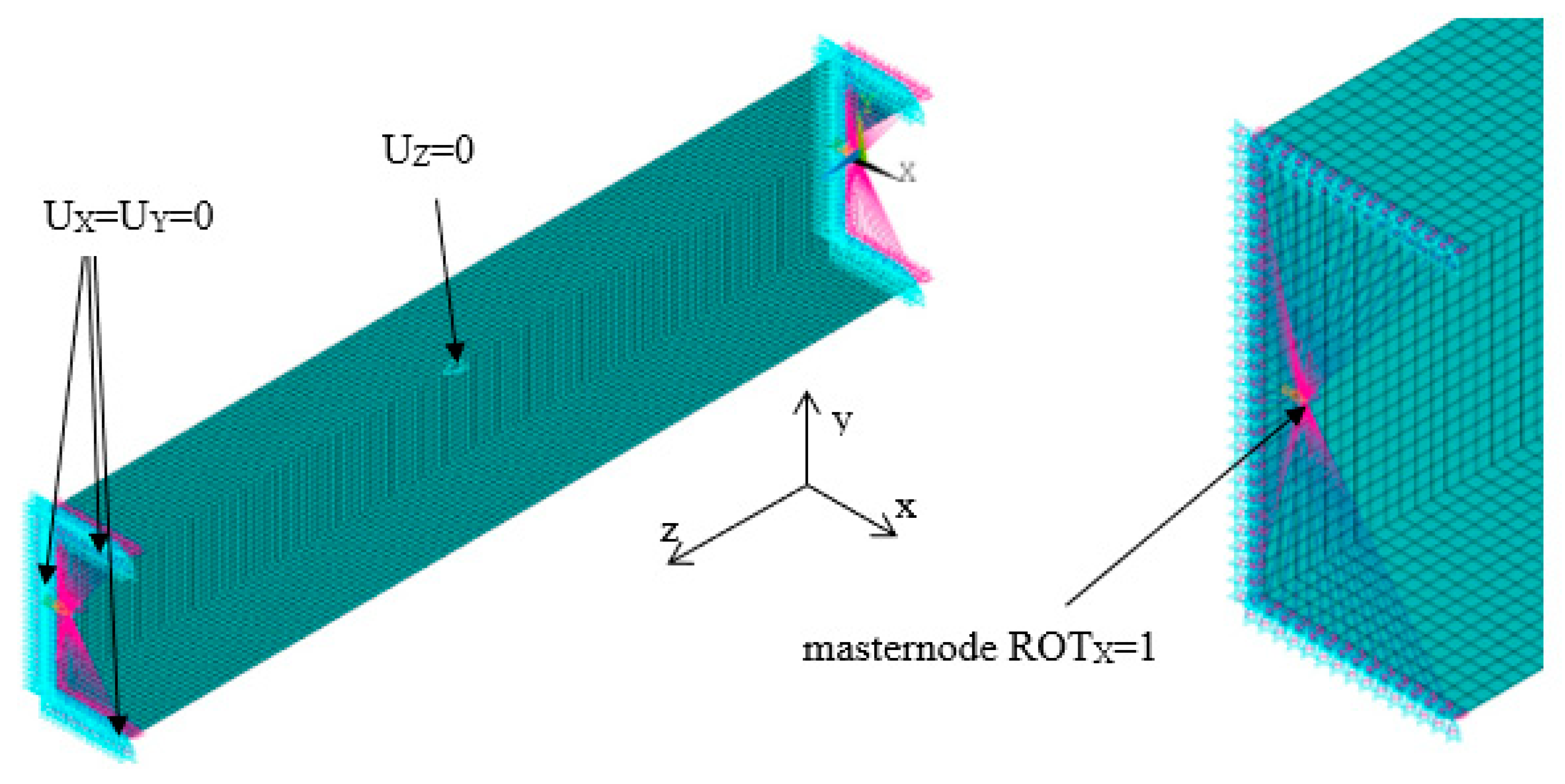
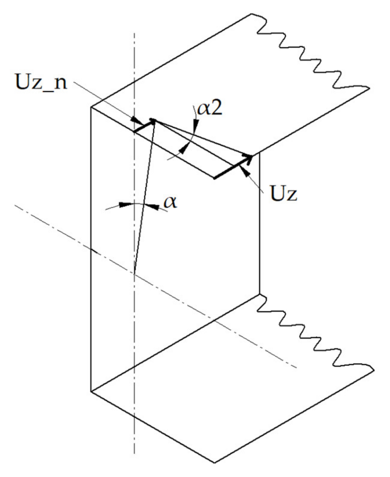
The numerical models were created using the structural SHELL 181 element. This element, with six degrees of freedom at each node, is described with first order shear deformation theory (Mindlin–Reissner shell theory). This finite element might be used in thin-walled structures to model the multi-layer structures [44]. The size of the finite element is equal to 3 mm in uniform mesh and it was determined based on the experience gained from the previous studies [46,47]. Boundary conditions were applied in the manner to ensure the pure bending with respect to major centroidal axis (Figure 3). Displacements in the vertical and transverse directions were blocked in the nodes located at both beam ends. The displacement in the longitudinal direction was set to zero in the point lying in mid-length of the beam and mid-width of the web. The load was introduced in the form of the angle of rotation in the bending plane. It was applied in the ‘master node’ which is located in the center of gravity of the cross-section and transferred to all nodes at both ends via RBE 2 elements via RBE 2 elements. The angle of rotation α was determined directly from the applied load while bending moment M was determined as the reaction (moment) in the ‘master node’ [46,47]. Additionally, the angle of rotation around the Y-axis, denoted as α2, was tracked. The analyzed angles α and α2 at the beam’s end are presented in Figure 4. The angle α2 was calculated using the following formula:
α 2 = arctg U z U z _ n x max
where:
Uz—Displacement of the point located on the free corner of compressed flange,
Uz_n—Displacement in the z-direction of the point located on the compressed flange and the central vertical axis,
xmax—Maximal distance from the central axis to the outer layer in the x-direction.

3. Results

In this section the results from performed numerical analysis are shown. Linear and non-linear buckling analysis were considered in order to obtain the full spectrum of the beam’s behavior. Critical buckling moments as well as the angle of rotation and equilibrium paths were determined.

3.1. Linear Buckling Analysis

Linear buckling analysis was performed using the Block Lanczos method to determine the buckling moments and corresponding angles of rotation for following buckling modes:
  • Local buckling mode (m > 1, where m is the number of half-waves in the longitudinal direction)
  • Primary global-distortional buckling mode (m = 1)
  • Secondary global-distortional buckling mode (m = 1 s)
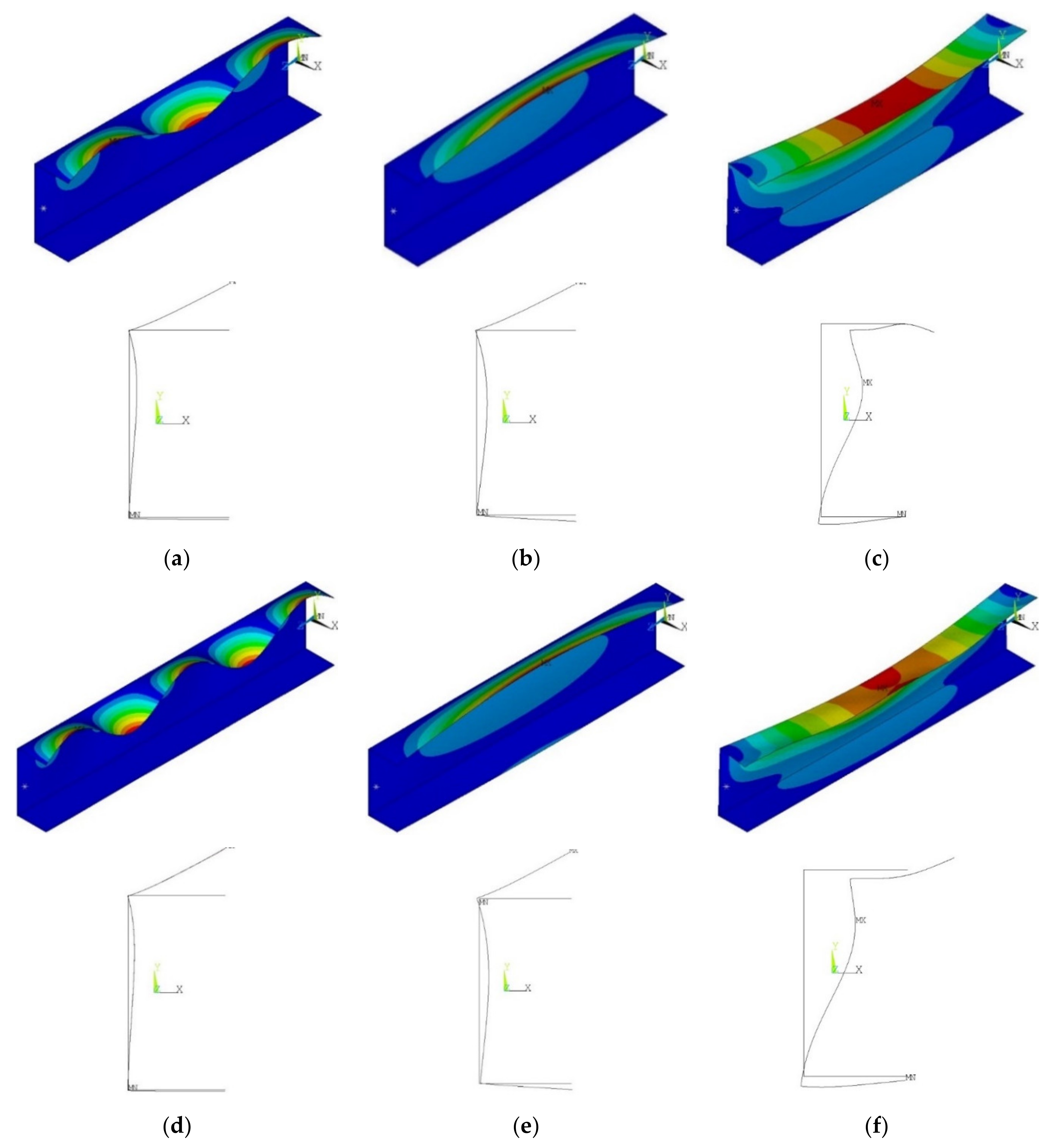
Considered buckling modes and the corresponding beam deflections are presented in Figure 5 while the buckling moments and corresponding angles of rotation are listed in Table 4. For beams with the length of 300 mm, the lowest buckling mode has the local character with three half-waves in the longitudinal direction, while for the beams with the length of 400 mm the lowest buckling mode was also the local mode, but with five half-waves in the longitudinal direction. The analysis of the deflection of the beam cross-section depicted that the secondary buckling mode for a 400 mm-length beam (Figure 5f) presents little greater flexural-distortional character compared to beam with L = 300 mm (Figure 5c).
Comparing the bifurcation loads for cases A and B (aluminium layer inside or outside), it could be observed that the localization of the FGM beam component has a negligible effect. Another conclusion could be made in the case of the adhesive layer. Implementation of the adhesive layer to the numerical models leads to the increase of the buckling loads (about 30%). Local bifurcation load is over 2.5 times smaller in comparison to primary global one (i.e., Mcr (m = 1)/Mcr (m > 1) > 2.6 and Mcr (m = 1 s)/Mcr (m = 1) > 4.7).

3.2. Non-Linear Buckling Analysis

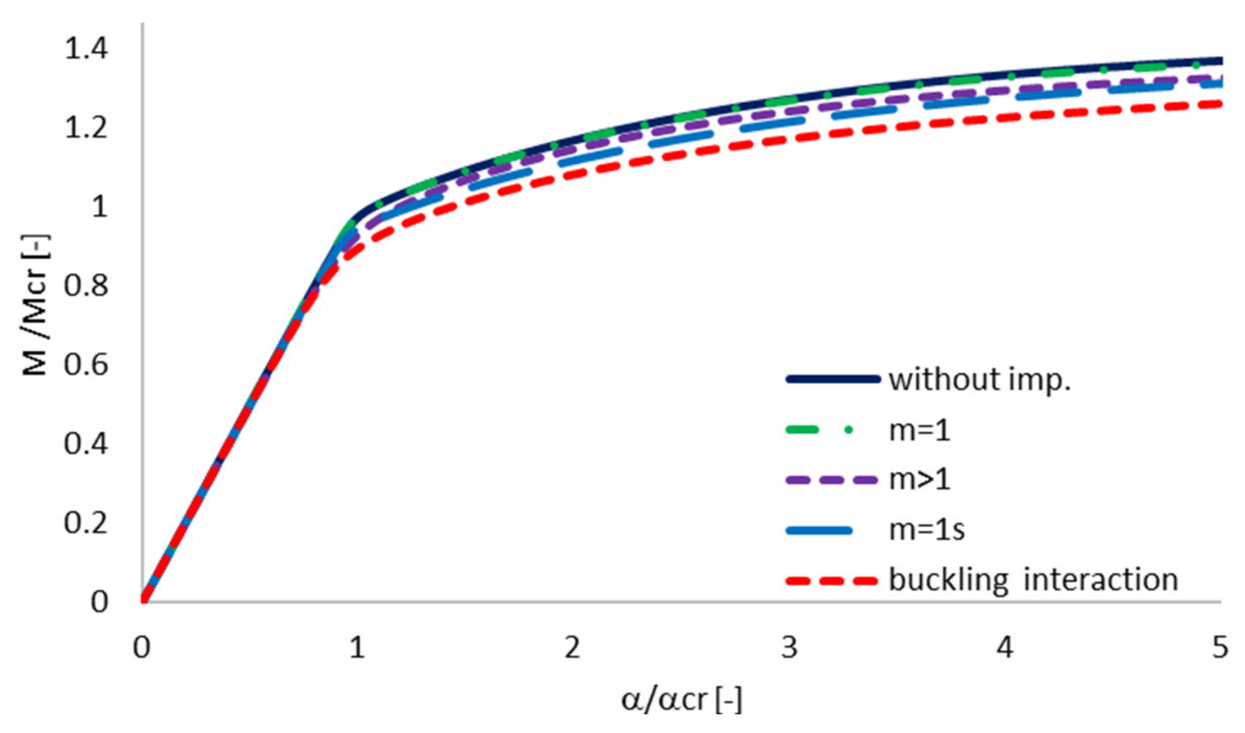
The non-linear buckling analysis with initial geometric imperfection was performed using the Newton–Raphson algorithm. The initial geometric imperfections were applied to the model with the shape corresponding to the considered buckling modes. The magnitude of the imperfection was assumed as 100% of wall thickness for primary and secondary global-buckling mode and 10% for a local one. Positive and negative imperfections were analyzed and the worst case of the sign (for which the lowest critical buckling moment was obtained) was chosen. Graphs of equilibrium paths were tracked for all analyzed samples. They show the ratio of buckling moment to the critical buckling moment (M/Mcr) in the function of angle of rotation to the critical one (α/αcr).
As the buckling interaction is analyzed, it is important to show the effect of each individual buckling mode as well as the interaction of the considered buckling modes on the equilibrium paths. The influence of different initial geometric imperfection on post-buckling equilibrium path is presented for one exemplary beam (beam 4A_50) in Figure 6. It was observed that initial imperfections affect post-buckling regime. In the pre-buckling range, all curves are almost coincident. Analyzing the one-mode approach, the highest effect on the structure response is observed when the geometric imperfections that corresponded to the secondary global distortional buckling mode are applied. Comparing all curves presented in Figure 6, the highest decrease of post-buckling stiffness and load-carrying capacity is obtained for multi-mode interaction.

3.3. The Effect of Aluminium and Titanium Thickness and Position

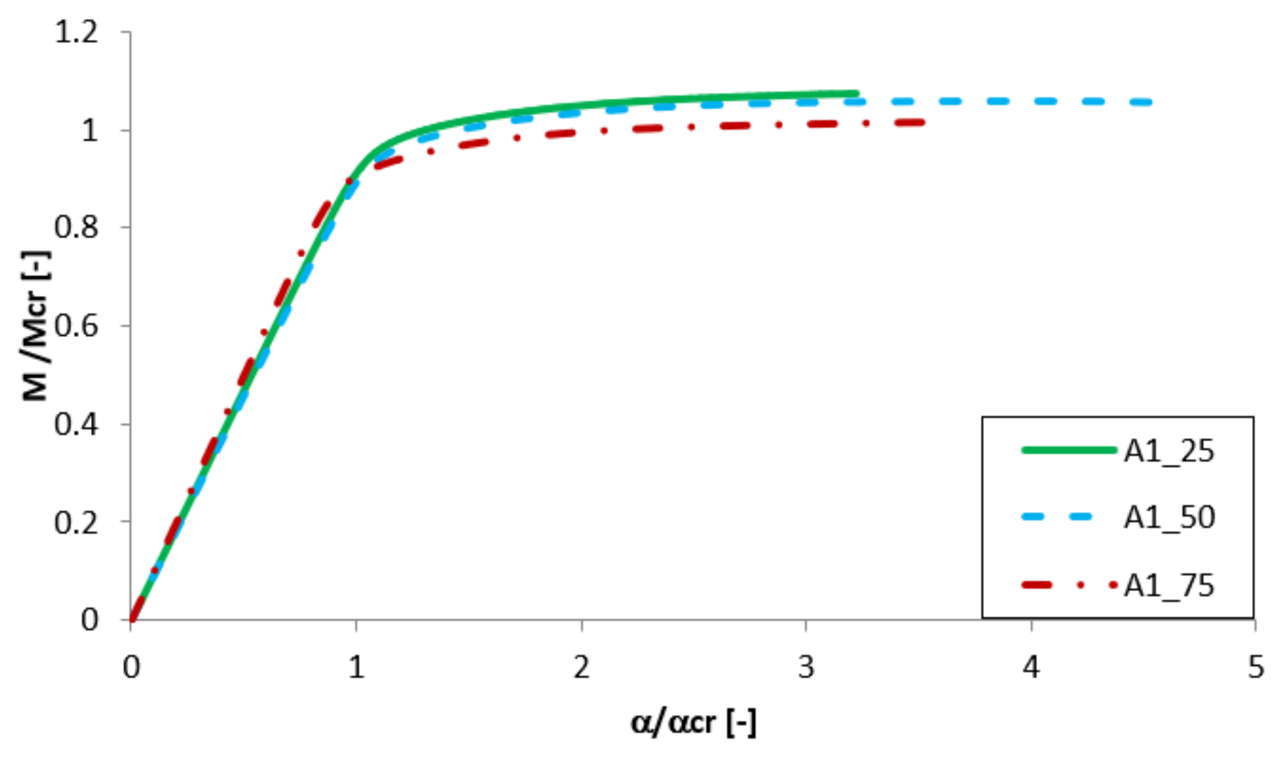
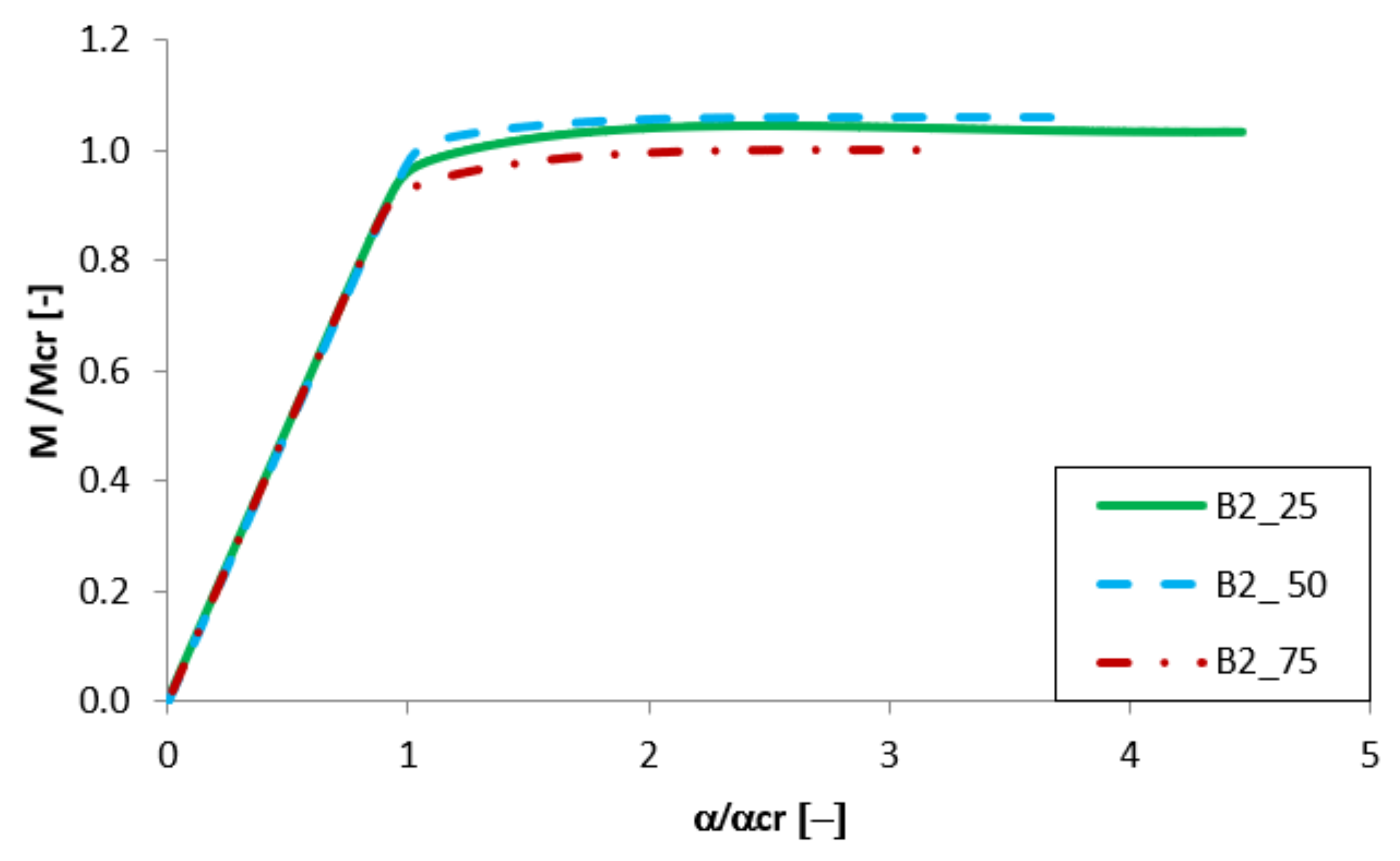
Equilibrium paths in the dimensionless form are presented in Figure 7, Figure 8, Figure 9 and Figure 10. The effect of the aluminium and titanium layer thickness for the beam with a total thickness of 1 mm is presented in Figure 7 and Figure 8, while for the cases with a total thickness of 2 mm in Figure 9 and Figure 10. Comparing both variants (A and B) for t = 1 mm, a greater influence of geometric imperfections on post-critical paths was observed for variant B (Figure 7 and Figure 8). The results shown in Figure 7, indicate the same stiffness in post-buckling range for beams A_25 and A_50. A beam with 75% of titanium presents lower stiffness. For variant A, the following tendency is observed—With the increase of the aluminium layer thickness, the non-dimensional load-carrying capacity decreases. This tendency is also valid for a beam with a thickness of 2 mm. However, for such beams (t = 2 mm) the effect of the aluminium layer position (outside—A or inside—B) is negligible.
Both variants A and B with assumed imperfections have ‘raising’ post-critical paths M/Mcr > 1 for the thickness of 1 mm, while for the thickness of 2 mm the load-carrying capacity practically does not exceed the critical load (i.e., M/Mcr ≈ 1). It proves that the higher internal forces occur in the beams with a thickness of 2 mm than for those with t = 1 mm [47].

3.4. The Effect of the Adhesive Layer

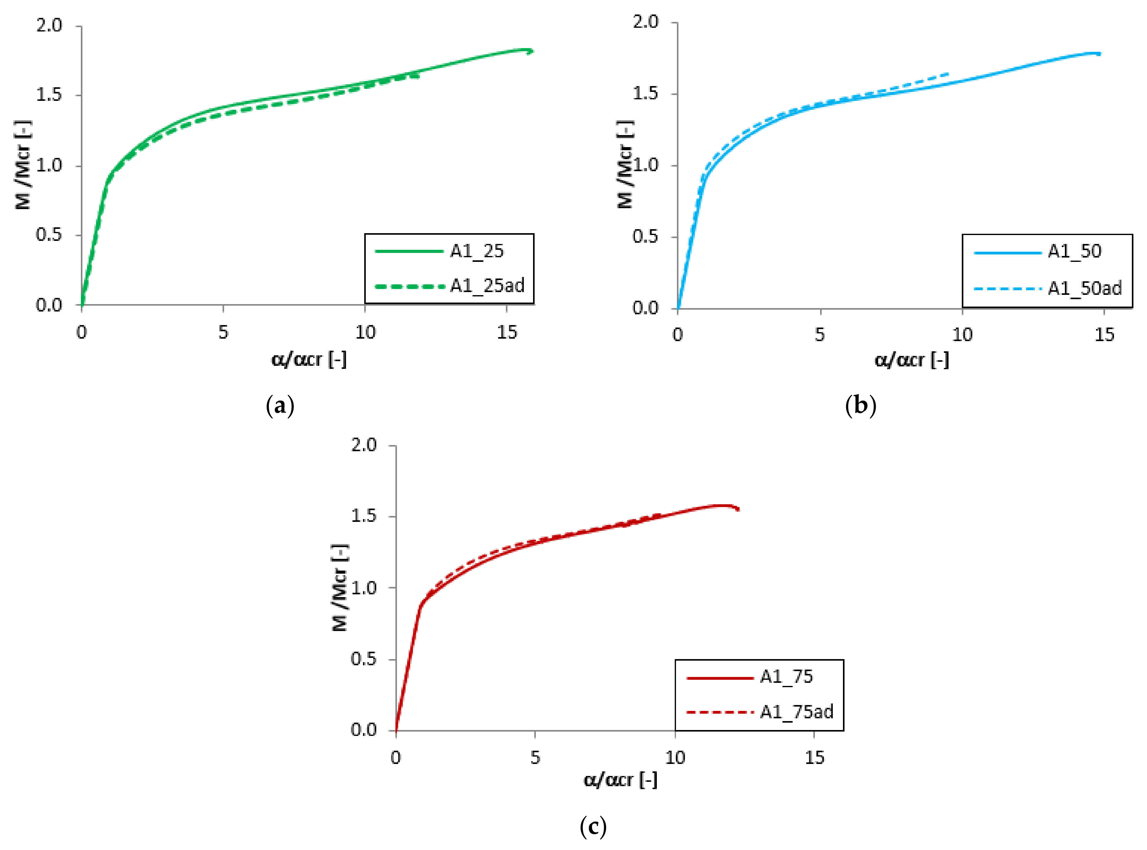
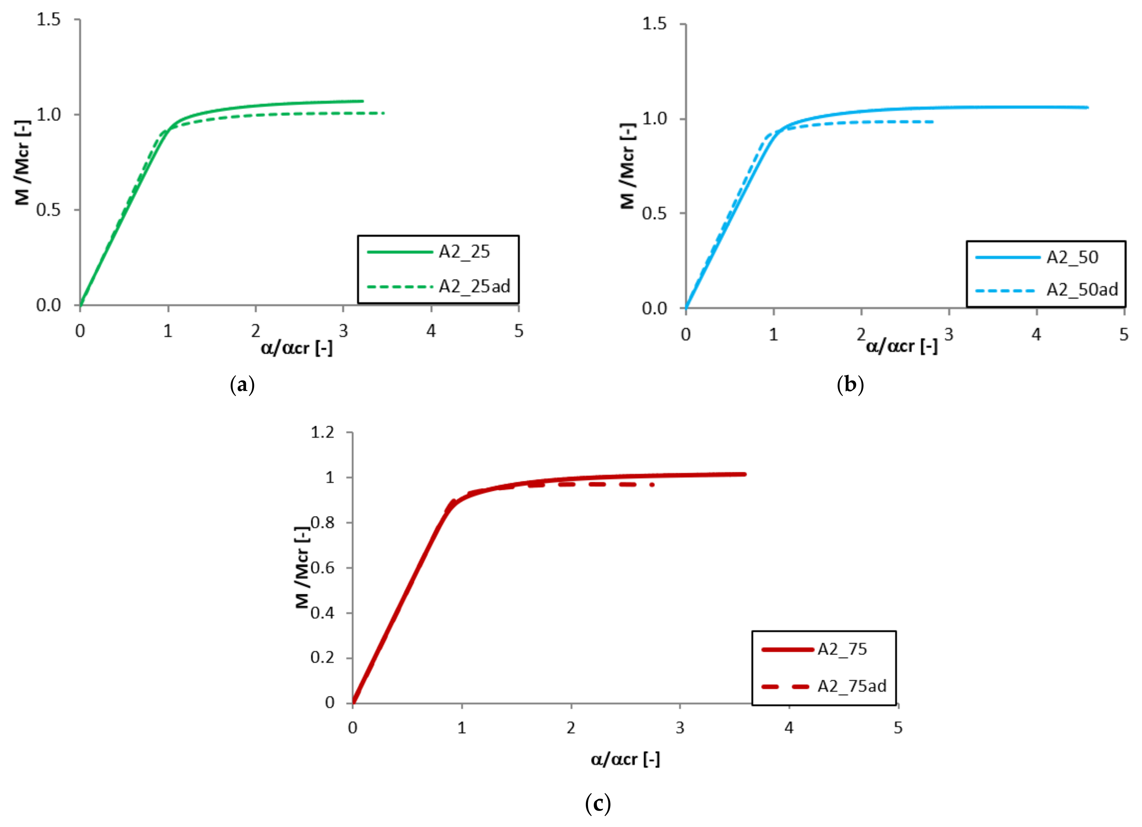
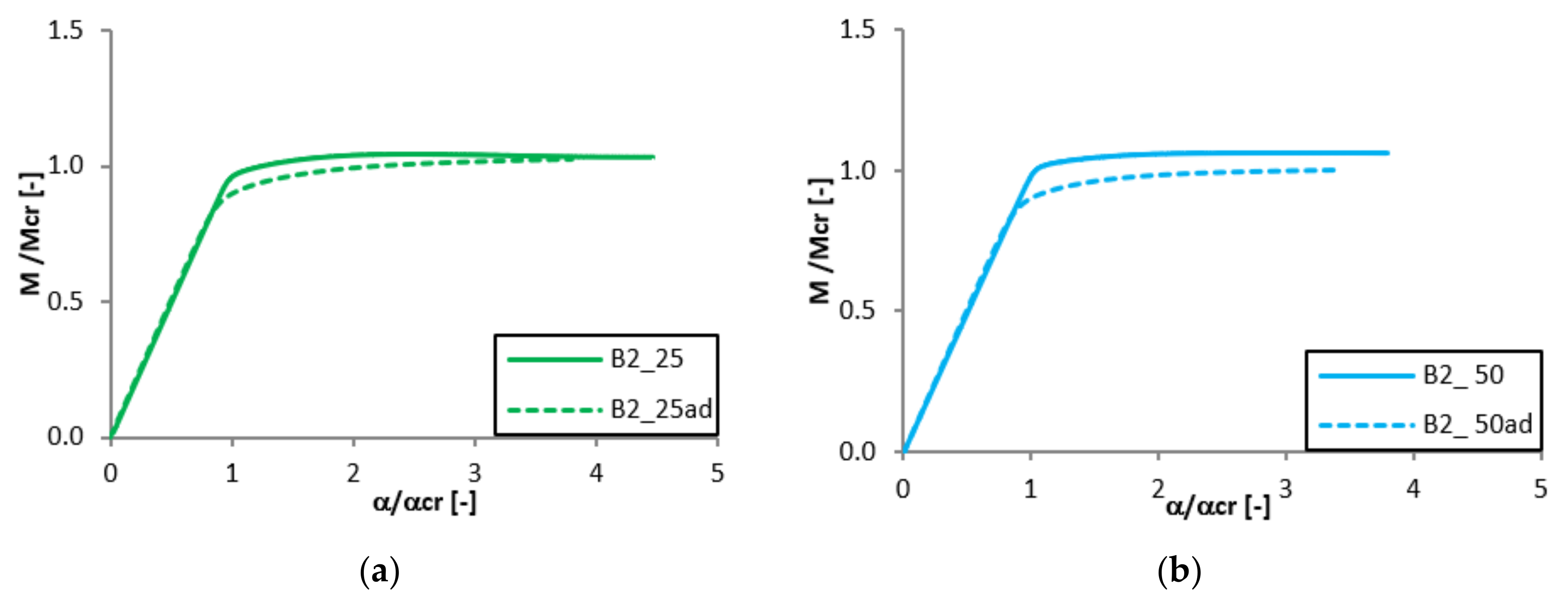
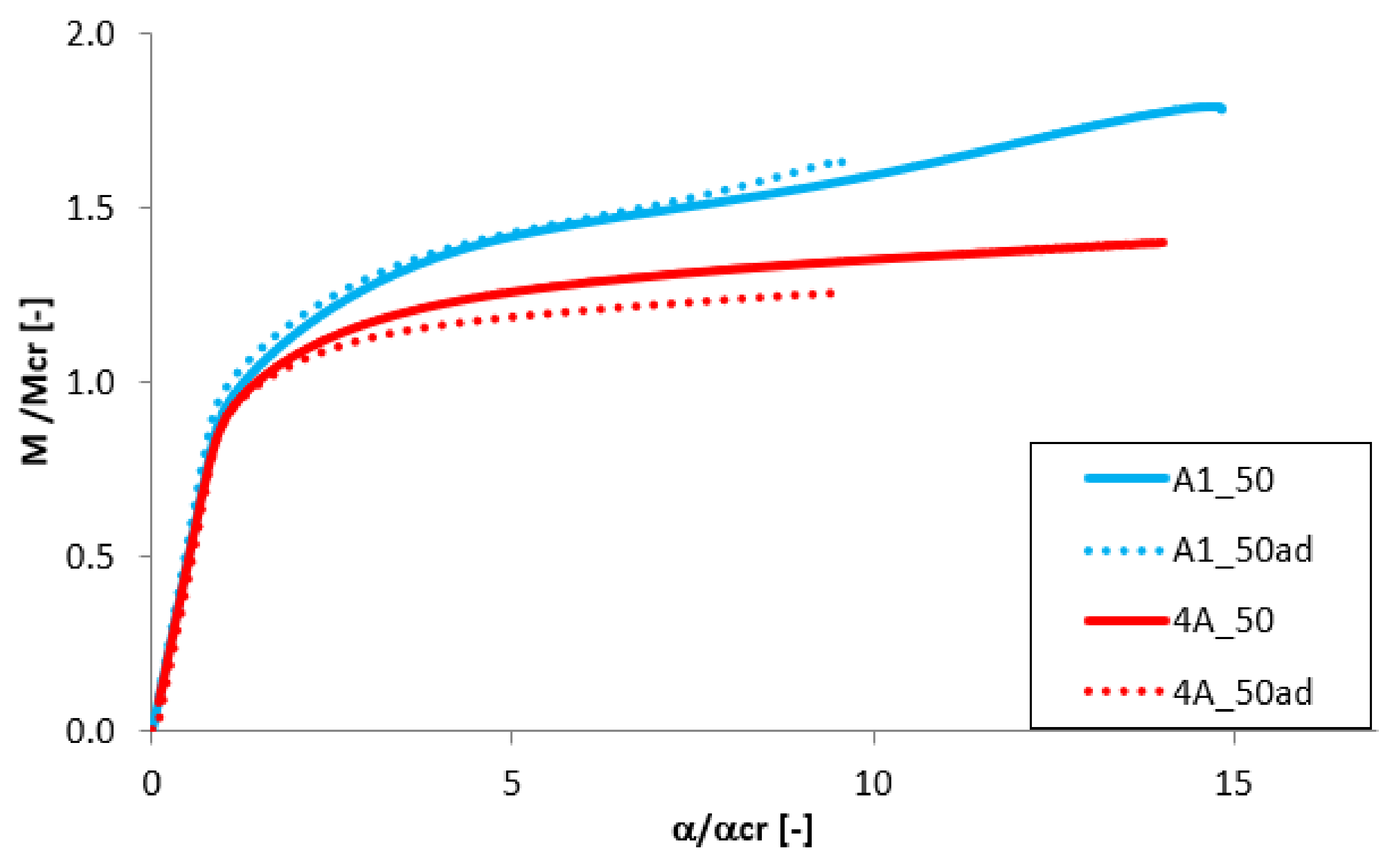
The analysis of the adhesive layer influence on the equilibrium paths is presented in Figure 11, Figure 12, Figure 13 and Figure 14. For almost all considered cases (except the beam B1_25 and B1_50) the adhesive layer leads to the decrease of the dimensionless load-carrying FGM beam capacity. Simultaneously, such a tendency of the equilibrium paths (mainly in the post-buckling range) remained unchanged. The only exceptions were the samples B1_25 and B1_50, where the addition of the adhesive layer led to the increase of the load-carrying capacity and the change of the post-critical behavior (Figure 12). For the beam A1_25 and B1_75ad (Figure 11 and Figure 12), a rapid decrease of the dimensionless bending moment and angle of rotation in the post-critical range was observed, and this phenomenon was deeply investigated in references [46,47,50].

3.5. The Effect of the Beam’s Length

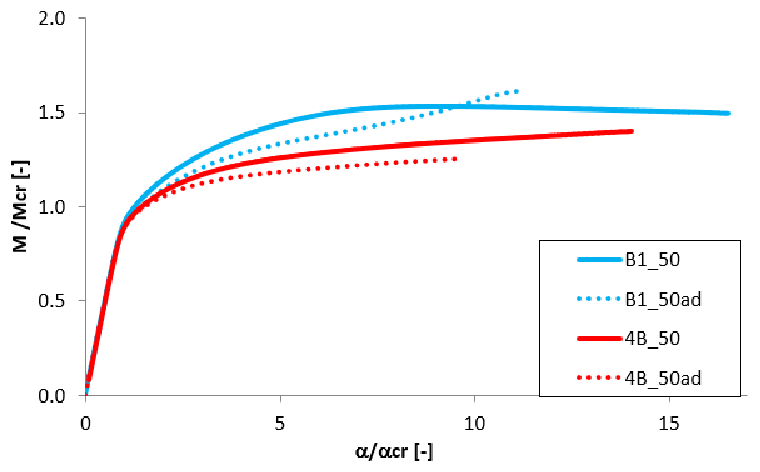
To analyze the effect of the beam’s length on the post-critical equilibrium paths, the results for beams with length of 300 mm and 400 mm and of equal thickness of individual layer tAl = tTi = 0.5 mm were compared. The results presented in Figure 15 and Figure 16 indicate the high differences in the post-buckling response. For shorter beam with L = 300 mm a slight increase of the bending moment is observed after the loss of stability (Figure 15), while for the longer beam the load increases slightly. Simultaneously, almost 40% drop of the dimensionless load-carrying capacity is observed for the beam with 400 mm length. For the variant B the difference in the maximum load is significantly smaller. However, also in this case, the change of the post-buckling equilibrium path occurs.
The presented tendency, in the results for analyzed samples could be explained by the difference in the shape of the buckling modes. As presented in Figure 5, the secondary distortional buckling mode for the beam with the length L = 400 mm presents a higher distortional effect (the entire displacement of the beam cross-section).
In Table 5, the dimensionless load-carrying capacity is compared for all cases. Interactive buckling results of FGM beams with 1 mm of a total wall thickness indicate the significant increase of the load-carrying capacity (Mmax/Mcr > 1.5 for L = 300 mm and Mmax/Mcr > 1.2 for L = 400 mm), while for the beams with a total wall thickness of 2 mm the ratio of Mmax/Mcr it takes place at around 1. The dimensionless load-carrying capacity remains almost unchanged with the different position of the aluminium layer in the FGM structure (cases A and B). An analogous tendency was obtained for the buckling load Mcr (Table 4).
In the presented paper authors have analyzed the impact of the modes for which the ratio of primary global mode to local one is higher than 2.6 and secondary global mode to primary one is higher than 4. Obtained results are in the good agreement with conclusions formulated in papers [44,45,46,50] about the impact of the secondary global buckling mode on the post-bifurcation equilibrium paths and the load-carrying capacity.

3.6. The Angle of Rotation at the Beam Ends

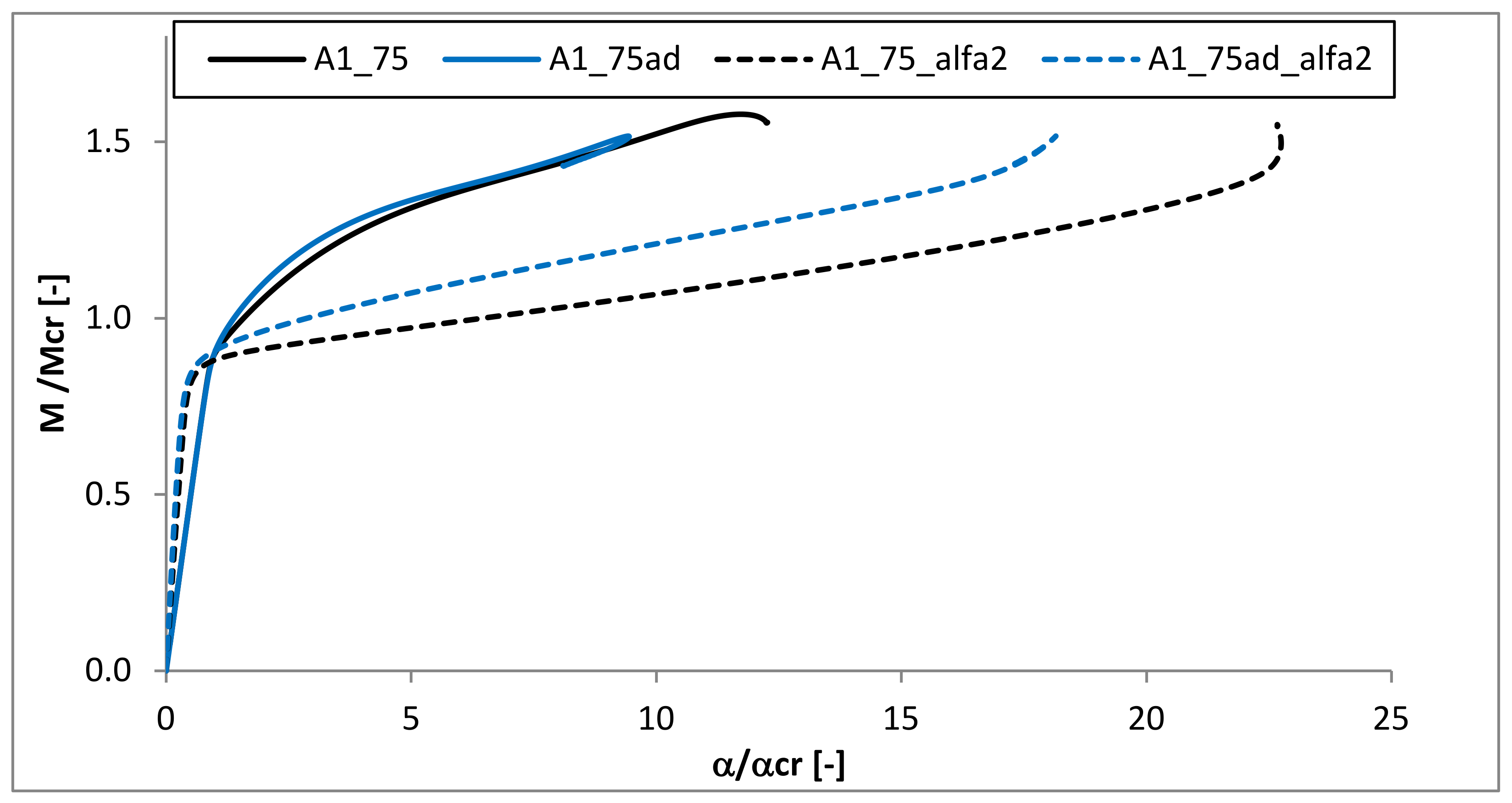
For the one exemplary case (A1_75), the comparison of the angles of rotation about two axes at the beam ends is presented in Figure 17. The angle α (angle in the plane of bending—about the major centroidal axis) is presented by solid lines, while the angle angle α2 in the plane YZ plane—about minor centroidal axis is marked with dashed ones. The analysis was performed for two samples which differed in the existence of the adhesive layer (A1_75 and A1_75ad). It could be observed, that for both beams, with and without adhesive layers, the angle α was about two times higher than α2 in the pre-buckling range. However, just after the critical point, the angle α2 increased rapidly. For the ratio M/Mcr = 1.2 the angle α2 was almost threefold (for A1_75ad) and fivefold (for A1_75) higher than the angle α. This proves the distortional character of the structure buckling. A similar tendency was also observed in [46].

4. Conclusions

Numerical investigations of the influence of the geometrical and material parameters on buckling and post-buckling behaviour of step-variable FGM medium-length beams were performed. Firstly, linear buckling analysis was carried out using ANSYS® 18.2 software. Subsequently, the non-linear analysis with the complex initial geometric imperfection was performed. It was observed that the thickness of the FGM components has an effect on the post-buckling equilibrium path, mainly for the beams with the total wall thickness of 1 mm. Implementation of the adhesive layer to the numerical models leads to similar buckling loads and to a slight decrease of the dimensionless load-carrying capacity. Comparing the results obtained for the beams of two lengths, it could be observed that for the longer beam the post-buckling equilibrium path was flatter. Additionally, the change of angle of rotation was analyzed. Rapid growth of the α2 angle in the post-buckling range was observed. The crucial influence of the secondary global buckling mode on the post-bifurcation beams’ behaviour under pure bending was confirmed.

Author Contributions

Conceptualization, M.Z.; methodology, M.Z.; software, M.Z., F.K.; formal analysis, M.Z., F.K. Writing—Original draft preparation, M.Z., F.K.; Writing—Review and editing, M.Z., F.K.; supervision, M.Z. All authors took a part in revision of the manuscript. All authors have read and agreed to the published version of the manuscript.

Funding

This research was funded by National Science Centre of Poland (UMO-2017/25/B/ST8/01046).

Acknowledgments

The work was carried out thanks to the financial support of the National Science Centre of Poland (UMO-2017/25/B/ST8/01046). The authors are grateful to prof. Zbigniew Kolakowski, for the substantive support.

Conflicts of Interest

The authors declare no conflicts of interest.

References

  1. Sai, H. A review on functionally gradient materials (FGMs) and their applications. Int. J. Curr. Eng. Technol. 2018, 8, 79–84. [Google Scholar] [CrossRef]
  2. Mahamood, M.; Akinlabi, E.T. Functionally Graded Materials, Topics in Mining, Metallurgy and Materials Engineering; Springer: Berlin/Heidelberg, Germany, 2017. [Google Scholar]
  3. Reddy, J.N. Analysis of functionally graded plates. Int. J. Numer. Meth. Eng. 2000, 47, 663–684. [Google Scholar] [CrossRef]
  4. Aydogdu, M.; Taskin, V. Free vibration analysis of functionally graded beams with simply supported edges. Mater. Des. 2007, 28, 1651–1656. [Google Scholar] [CrossRef]
  5. Suresh, S.; Mortensen, A. Fundamentals of Functionally Graded Materials: Processing and Thermomechanical Behavior of Graded Metals and Metallic-Ceramic Composites; IOM Communications Ltd.: London, UK, 1998. [Google Scholar]
  6. Zhang, X.; Chen, F.; Zhang, H. Stability and local bifurcation analysis of functionally graded material plate under transversal and in-plane excitations. Appl. Math. Model. 2013, 37, 6639–6651. [Google Scholar] [CrossRef]
  7. Babaei, H.; Eslami, M.R.; Khorshidvand, A.R. Thermal buckling and postbuckling responses of geometrically imperfect FG porous beams based on physical neutral plane. J. Therm. Stresses 2020, 43, 109–131. [Google Scholar] [CrossRef]
  8. Do, V.N.V.; Lee, C.H. Quasi-3D higher-order shear deformation theory for thermal buckling analysis of FGM plates based on a meshless method. Aerosp. Sci. Technol. 2018, 82, 450–465. [Google Scholar] [CrossRef]
  9. Do, V.N.V.; Lee, C. Thermal buckling analyses of FGM sandwich plates using the improved radial point interpolation mesh-free method. Compos. Struct. 2017, 177, 171–186. [Google Scholar] [CrossRef]
  10. Zhang, J.; Chen, L.; Lv, Y. Elastoplastic thermal buckling of functionally graded material beams. Compos. Struct. 2019, 224, 111014. [Google Scholar] [CrossRef]
  11. Sohn, K.J.; Kim, J.H. Structural stability of functionally graded material plates subjected to aero-thermal loads. Compos. Struct. 2008, 82, 317–325. [Google Scholar] [CrossRef]
  12. Moita, J.S.; Araújo, A.L.; Correia, V.F.; Mota Soares, C.M.; Herskovits, J. Buckling behavior of composite and functionally graded material plates. Eur. J. Mech. A/Solids 2020, 80, 1–10. [Google Scholar] [CrossRef]
  13. Taczała, M.; Buczkowski, R.; Kleiber, M. Postbuckling analysis of functionally graded plates on an elastic foundation. Compos. Struct. 2015, 132, 842–847. [Google Scholar] [CrossRef]
  14. Prakash, T.; Singha, M.; Ganapathi, M. Influence of neutral surface position on the nonlinear stability behavior of functionally graded plates. Comput. Mech. 2009, 43, 341–350. [Google Scholar] [CrossRef]
  15. Shen, H.S. Post buckling of FGM plates with piezoelectric actuators under thermo-electro-mechanical loadings. Int. J. Solids Struct. 2005, 42, 6101–6121. [Google Scholar] [CrossRef] [Green Version]
  16. Burzynski, S.; Chroscielewski, J.; Daszkiewicz, K.; Witkowski, W. Geometrically nonlinear FEM analysis of FGM shells based on neutral physical surface approach in 6-parameter shell theory. Compos. Part B Eng. 2016, 107, 203–213. [Google Scholar] [CrossRef]
  17. Burzynski, S.; Chroscielewski, J.; Daszkiewicz, K.; Witkowski, W. Elastoplastic nonlinear FEM analysis of FGM shells of Cosserat type. Compos. Part B Eng. 2018, 154, 478–491. [Google Scholar] [CrossRef]
  18. Sobhy, M. An accurate shear deformation theory for vibration and buckling of FGM sandwich plates in hygrothermal environment. Int. J. Mech. Sci. 2016, 10, 62–77. [Google Scholar] [CrossRef]
  19. Kumar, R.; Lal, A.; Singh, B.N.; Singh, J. New transverse shear deformation theory for bending analysis of FGM plate under patch load. Compos. Struct. 2019, 208, 91–100. [Google Scholar] [CrossRef]
  20. Meiche, N.E.; Tounsi, A.; Ziane, N.; Mechab, I.; Addia Bedia, E.A. A new hyperbolic shear deformation theory for buckling and vibration of functionally graded sandwich plate. Int. J. Mech. Sci. 2011, 53, 237–241. [Google Scholar] [CrossRef]
  21. Daneshmehra, A.; Heydaria, M.; Khorshidia, M.A. Post-buckling analysis of FGM beams according to different shear deformation theories. Int. J. Multidiscip. Curr. Res. 2013, 1, 37–49. [Google Scholar]
  22. Farhatnia, F.; Sarami, M. Finite element approach of bending and buckling analysis of FG beams based on refined zigzag theory. Uni. J. Mech. Eng. 2019, 7, 147–158. [Google Scholar] [CrossRef]
  23. Ghiasian, S.E.; Kiani, Y.; Eslami, M.R. Nonlinear thermal dynamic buckling of FGM beams. Eur. J. Mech. A/Solids 2015, 54, 232–242. [Google Scholar] [CrossRef]
  24. Zeverdejeni, M.K.; Beni, Y.T.; Kiani, Y. Multi-scale buckling and post-buckling analysis of functionally graded laminated composite plates reinforced by defective graphene sheets. Int. J. Struct. Stab. Dynam. 2019, 20, 1. [Google Scholar] [CrossRef]
  25. Kiani, Y. Axisymmetric static and dynamics snap-through phenomena in a thermally postbuckled temperature-dependent FGM circular plate. Int. J. Non-Linear Dynam. 2016, 89, 1–13. [Google Scholar] [CrossRef]
  26. Czechowski, L. Study of dynamic buckling of FG plate due to heat flux pulse. Int. J. Appl. Mech. Eng. 2015, 20, 19–31. [Google Scholar] [CrossRef] [Green Version]
  27. Czechowski, L. Analysis of dynamic response of functionally graded plate due to temperature pulse load. Compos. Struct. 2016, 160, 625–634. [Google Scholar] [CrossRef]
  28. Czechowski, L.; Kowal-Michalska, K. Static and dynamic buckling of rectangular functionally graded plates subjected to thermal loading. Strength Mater. 2013, 45, 666–673. [Google Scholar] [CrossRef]
  29. Zhang, J.; Li, S. Dynamic buckling of FGM truncated conical shells subjected to non-uniform normal impact load. Compos. Struct. 2010, 92, 2979–2983. [Google Scholar] [CrossRef]
  30. Zhang, J.; Chen, S.; Zweng, W. Dynamic buckling analysis of functionally graded material cylindrical shells under thermal shocks. Contin. Mech. Thermodyn. 2019, 55, 1–14. [Google Scholar] [CrossRef]
  31. Kolakowski, Z. Some aspects of interactive dynamic stability of thin-walled trapezoidal FGM beam-columns under axial load. Thin-Walled Struct. 2016, 98, 431–442. [Google Scholar] [CrossRef]
  32. Kolakowski, Z.; Teter, A. Static interactive buckling of functionally graded columns with close cross-sections subjected to axial compression. Compos. Struct. 2015, 123, 257–262. [Google Scholar] [CrossRef]
  33. Kolakowski, Z.; Teter, A. Load carrying capacity of functionally graded columns with open cross-sections under static compression. Compos. Struct. 2015, 129, 1–7. [Google Scholar] [CrossRef]
  34. Kolakowski, Z.; Mania, R.J. Influence of the coupling matrix B on the interactive buckling of FML-FGM columns with closed cross-sections under axial compression. Compos. Struct. 2017, 173, 70–77. [Google Scholar] [CrossRef]
  35. Teter, A.; Mania, R.J.; Kolakowski, Z. Non-linear multi-mode buckling of non-symmetric FML/FGM thin-walled columns with open cross-sections under compression. Compos. Struct. 2017, 167, 38–49. [Google Scholar] [CrossRef]
  36. Huang, X.H.; Yang, J.; Liu, Q.; Zhu, J.; Bai, L.; Wang, F.; Wang, J. A simplified flange-lip model for distortional buckling of cold-formed steel channel-sections with stiffened web. Int. J. Mech. Sci. 2018, 136, 451–459. [Google Scholar] [CrossRef]
  37. Camotim, D.; Dinis, P.B. Coupled instabilities with distortional buckling in cold-formed steel lipped channel columns. Thin-Wall Struct. 2011, 49, 562–575. [Google Scholar] [CrossRef]
  38. Camotim, D.; Dinis, P.B.; Martins, A.D.; Young, B. Review: Interactive behaviour, failure and DSM design of cold-formed steel members prone to distortional buckling. Thin-Wall Struct. 2018, 128, 12–42. [Google Scholar] [CrossRef]
  39. Chen, M.T.; Young, B.; Martins, A.D.; Camotim, D.; Dinis, P.B. Experimental investigation on cold-formed steel stiffened lipped channel columns undergoing local-distortional interaction. Thin-Walled Struct. 2020, 150, 106682. [Google Scholar] [CrossRef]
  40. Martins, A.D.; Gonçalves, R.; Camotim, D. Post-buckling behaviour of thin-walled regular polygonal tubular columns undergoing local–distortional interaction. Thin-Walled Struct. 2019, 138, 373–391. [Google Scholar] [CrossRef]
  41. Niu, R.; Rasmussen, K.J.R.; Fan, F. Distortional–global interaction buckling of stainless steel C-beams: Part I—Experimental investigation. J. Constr. Steel Res. 2014, 96, 127–139. [Google Scholar] [CrossRef]
  42. Niu, R.; Rasmussen, K.J.R.; Fan, F. Distortional–global interaction buckling of stainless steel C-beams: Part II—Numerical study and design. J. Constr. Steel Res. 2014, 96, 40–53. [Google Scholar] [CrossRef]
  43. Kolakowski, Z. A semi-analytical method of interactive buckling of thin-walled elastic structures in the second order approximation. Int. J. Solids Struct. 1996, 33, 3779–3790. [Google Scholar] [CrossRef]
  44. Kolakowski, Z.; Jankowski, J. Interactive buckling of steel C-beams with different lengths—From short to long beams. Thin-Walled Struct. 2018, 125, 203–210. [Google Scholar] [CrossRef]
  45. Kolakowski, Z.; Jankowski, J. Interactive buckling of steel LC-beams under bending. Materials 2019, 12, 1440. [Google Scholar] [CrossRef] [PubMed] [Green Version]
  46. Kolakowski, Z.; Kubiak, T.; Kamocka, M. Coupled buckling of steel LC-beams under bending. In Stability and Ductility of Steel Structures; Wald, F., Jandera, M., Eds.; CRC Press: Boca Raton, FL, USA, 2019; pp. 614–621. [Google Scholar]
  47. Zaczynska, M.; Kolakowski, Z. The influence of the internal forces of the buckling modes on the load-carrying capacity of composite medium length beams under bending. Materials 2020, 13, 445. [Google Scholar] [CrossRef] [Green Version]
  48. ANSYS, Inc. User’s Guide ANSYS® 18.2; Ansys, Inc.: Canonsburg, PA, USA, 2018. [Google Scholar]
  49. Huntsman. Available online: https://prostech.vn/wp-content/uploads/2019/01/Araldite-AW-4804-_-Hardener-HW-4804.pdf (accessed on 4 June 2019).
  50. Kolakowski, Z.; Kubiak, T.; Zaczynska, M.; Kazmierczyk, F. Global-distortional buckling mode influence on post-buckling behaviour of lip-channel beams. Int. J. Mech. Sci. 2020, 105723, in press. [Google Scholar] [CrossRef]
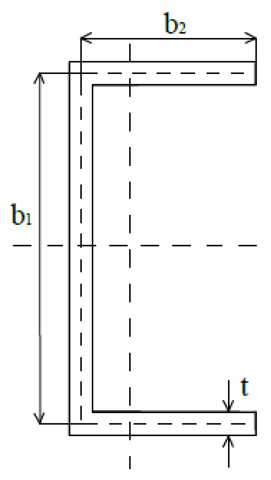
Figure 1. Dimensions of the cross-section.
Materials 13 02567 g001
Figure 2. Signature curve of exemplary functionally graded material (FGM) beam.
Materials 13 02567 g002
Figure 3. Discretized numerical model with applied boundary conditions.
Materials 13 02567 g003
Figure 4. The scheme of the angles of rotation α and α2 at the beam’s end.
Materials 13 02567 g004
Figure 5. Finite element method (FEM) buckling modes: (a) m = 3—local buckling mode for L = 300 mm; (b) m = 1 global distortional-lateral buckling mode for L = 300 mm; (c) m = 1 s secondary global distortional-lateral buckling mode for L = 300 mm; (d) m = 5—local buckling mode for L = 400 mm; (e) m = 1 global distortional-lateral buckling mode for L = 400 mm; (f) m = 1 s secondary global distortional-lateral buckling mode for L = 400 mm.
Materials 13 02567 g005
Figure 6. The effect of different initial geometric imperfection on equilibrium path for 4A_50 beam.
Materials 13 02567 g006
Figure 7. Comparison of equilibrium paths for A beam with a total thickness of 1 mm.
Materials 13 02567 g007
Figure 8. Comparison of equilibrium paths for B beam with a total thickness of 1 mm.
Materials 13 02567 g008
Figure 9. Comparison of equilibrium paths for A beam with a total thickness of 2 mm.
Materials 13 02567 g009
Figure 10. Comparison of equilibrium paths for B beam with a total thickness of 2 mm.
Materials 13 02567 g010
Figure 11. The effect of the adhesive layer for A beam with 1 mm thickness: (a) tTi = 0.25 mm; (b) tTi = 0.50 mm; (c) tTi = 0.25 mm.
Materials 13 02567 g011
Figure 12. The effect of the adhesive layer for B beam with 1 mm thickness: (a) tTi = 0.25 mm; (b) tTi = 0.50 mm; (c) tTi = 0.25 mm.
Materials 13 02567 g012
Figure 13. The effect of the adhesive layer for A beam with 2 mm thickness: (a) tTi = 0.50 mm; (b) tTi = 1.00 mm; (c) tTi = 1.50 mm.
Materials 13 02567 g013
Figure 14. The effect of the adhesive layer for B beam with 2 mm thickness: (a) tTi = 0.50 mm; (b) tTi = 1.00 mm; (c) tTi = 1.50 mm.
Materials 13 02567 g014aMaterials 13 02567 g014b
Figure 15. The effect of the beam length for variant A.
Materials 13 02567 g015
Figure 16. The effect of the beam length for variant B.
Materials 13 02567 g016
Figure 17. The comparison of the angle of rotation around two axes at the beam end.
Materials 13 02567 g017
Table 1. Characteristic parameters of the considered beams.
Total Wall Thickness—t (mm)Width of the Web—b1 (mm)Width of the Flange—b2 (mm)Length of the Beam—L (mm)
1–2.18040300; 400
Table 2. Lists of the analyzed samples.
L (mm)NameCaseThickness (mm)NameCaseThickness (mm)
tAltTitAdtAltTitAd
300A1_75A0.250.750.00B1_75B0.250.750.00
A1_75adA0.250.750.10B1_75adB0.250.750.10
A1_50A0.500.500.00B1_50B0.500.500.00
A1_50adA0.500.500.10B1_50adB0.500.500.10
A1_25A0.750.250.00B1_25B0.750.250.00
A1_25adA0.750.250.10B1_25adB0.750.250.10
A2_75A1.500.500.00B2_75B1.500.500.00
A2_75adA1.500.500.10B2_75adB1.500.500.10
A2_50A1.001.000.00B2_50B1.001.000.00
A2_50adA1.001.000.10B2_50adB1.001.000.10
A2_25A0.501.500.00B2_25B0.501.500.00
A2_25adA0.501.500.10B2_25adB0.501.500.10
4004A_50A0.500.500.004B_50B0.500.500.00
4A_50adA0.500.500.104B_50adB0.500.500.10
Table 3. Mechanical properties of FGM’s beam components.
MaterialE (GPa)ν
Titanium Ti-5Al-2.5Sn1070.34
Aluminium EN AW-2024 (AlCu4Mg1)710.33
Adhesive Araldite AW 4804 [49]6.20.4
Table 4. Comparison of buckling loads.
NameModeMcr (Nm)αcr (°)NameModeMcr (Nm)αcr (°)Mcr(A)/Mcr(B) (-)
A1_7531780.11B1_7531770.111.01
15020.3214970.311.01
1 s65164.111 s65464.120.99
A1_75ad32260.14B1_75ad32250.141.00
16350.4016310.391.01
1 s67324.211 s67744.230.99
A1_5031810.10B1_5031790.101.01
15100.2915050.291.01
1 s71704.071 s72414.100.99
A1_50ad32370.13B1_50ad32350.131.01
16700.3816620.371.01
1 s74194.181 s75034.220.99
A1_2531880.10B1_2531870.101.01
15320.2715280.271.01
1 s781540.391 s78894.050.99
A1_25ad32290.12B1_25ad32270.121.01
16470.3316390.331.01
1 s80534.131 s81434.160.99
A2_75313890.43B2_75314080.440.83
137261.18136661.150.85
1 s148104.661 s150084.720.88
A2_75ad315740.49B2_75ad315560.491.01
141471.30140891.301.01
1 s150834.741 s152574.740.99
A2_50314100.36B2_50314330.410.98
138211.09137481.061.02
1 s16,2264.611 s16,5194.670.98
A2_50ad316290.46B2_50ad316000.461.02
143321.23142421.231.02
1 s16,5664.691 s16,8514.690.98
A2_25314740.38B2_25314910.380.99
139911.03139391.011.01
1 s17,8734.601 s18,0674.640.99
A2_25ad316380.42B2_25ad316120.421.02
143701.12142931.121.02
1 s180604.641 s183304.640.99
4A1_5051810.144B1_5051790.141.01
17840.5917760.591.01
1 s46433.511 s46843.530.99
4A1_50ad52370.184B1_50ad52350.181.01
110170.76110040.751.01
1 s47863.601 s48363.620.99
Table 5. Comparison of load-carrying capacity.
NameMmax/McrNameMmax/Mcr
A1_751.578B1_751.589
A1_75ad1.516B1_75ad1.539
A1_501.788B1_501.532
A1_50ad1.637B1_50ad1.613
A1_251.832B1_251.649
A1_25ad1.646B1_25ad1.695
A2_751.014B2_751.002
A2_75ad0.971B2_75ad0.977
A2_501.060B2_501.062
A2_50ad0.986B2_50ad0.99
A2_251.074B2_251.045
A2_25ad1.016B2_25ad1.028
4A1_501.3994B1_501.437
4A1_50ad1.2564B1_50ad1.267