Effects of CNC Machining on Surface Roughness in Fused Deposition Modelling (FDM) Products


Abstract
:1. Introduction
2. Literature Review
3. Materials and Methods
4. Results and Discussion
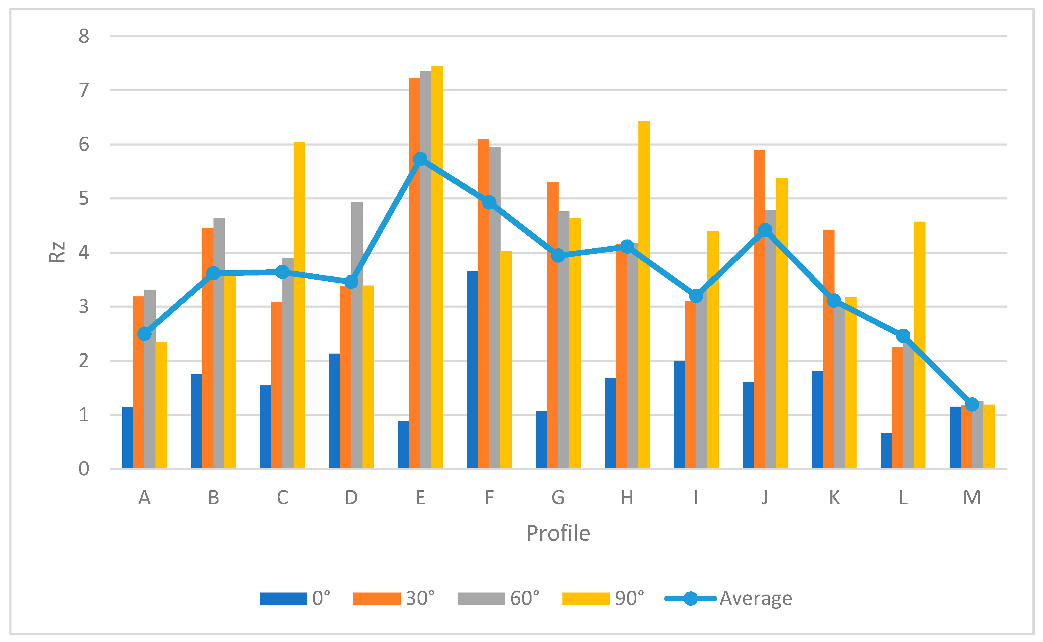
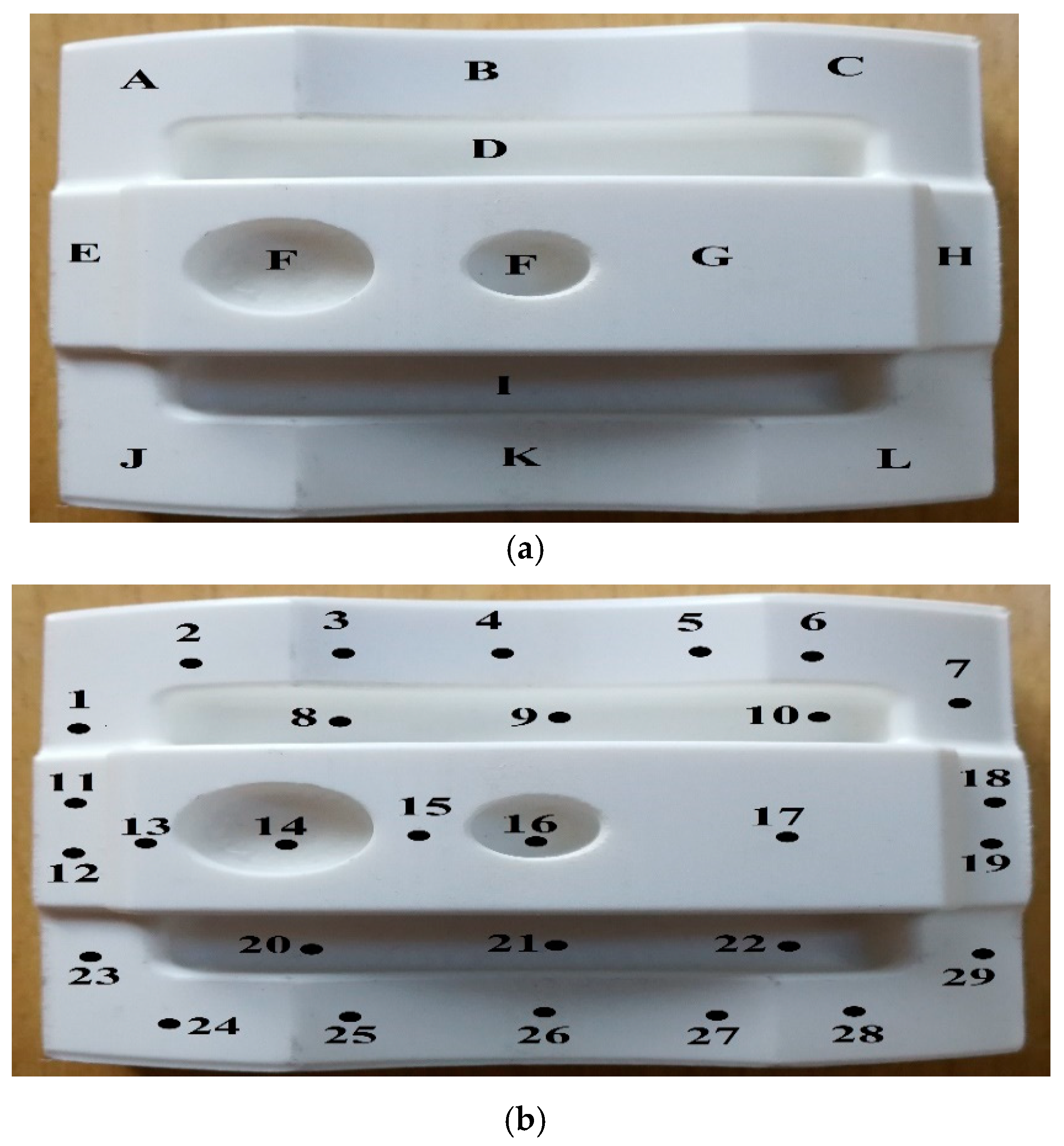
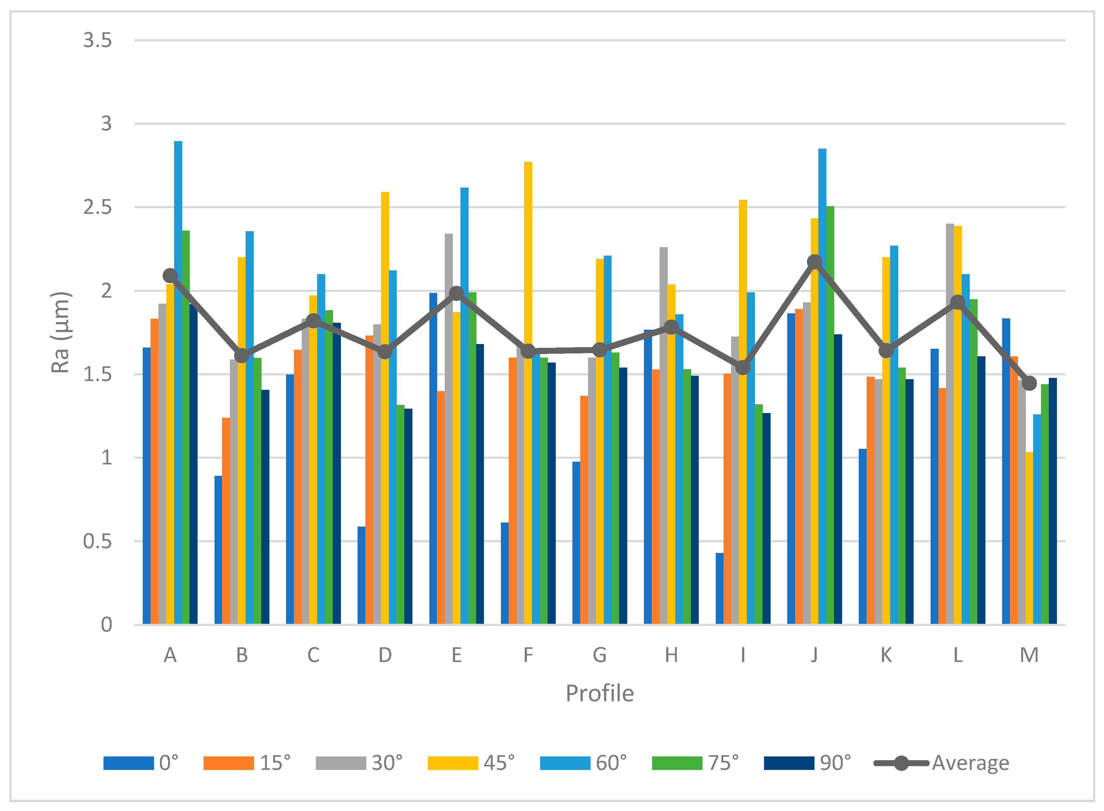
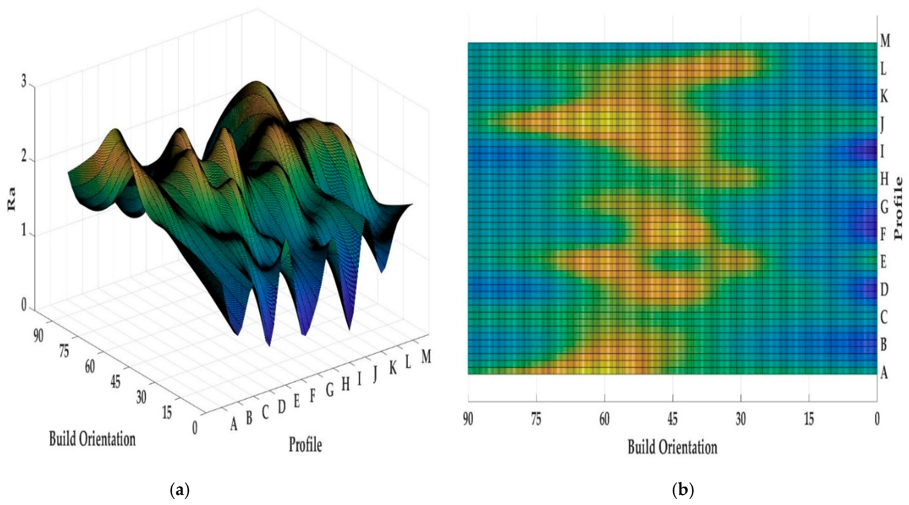
4.1. Surface Profile Measurement
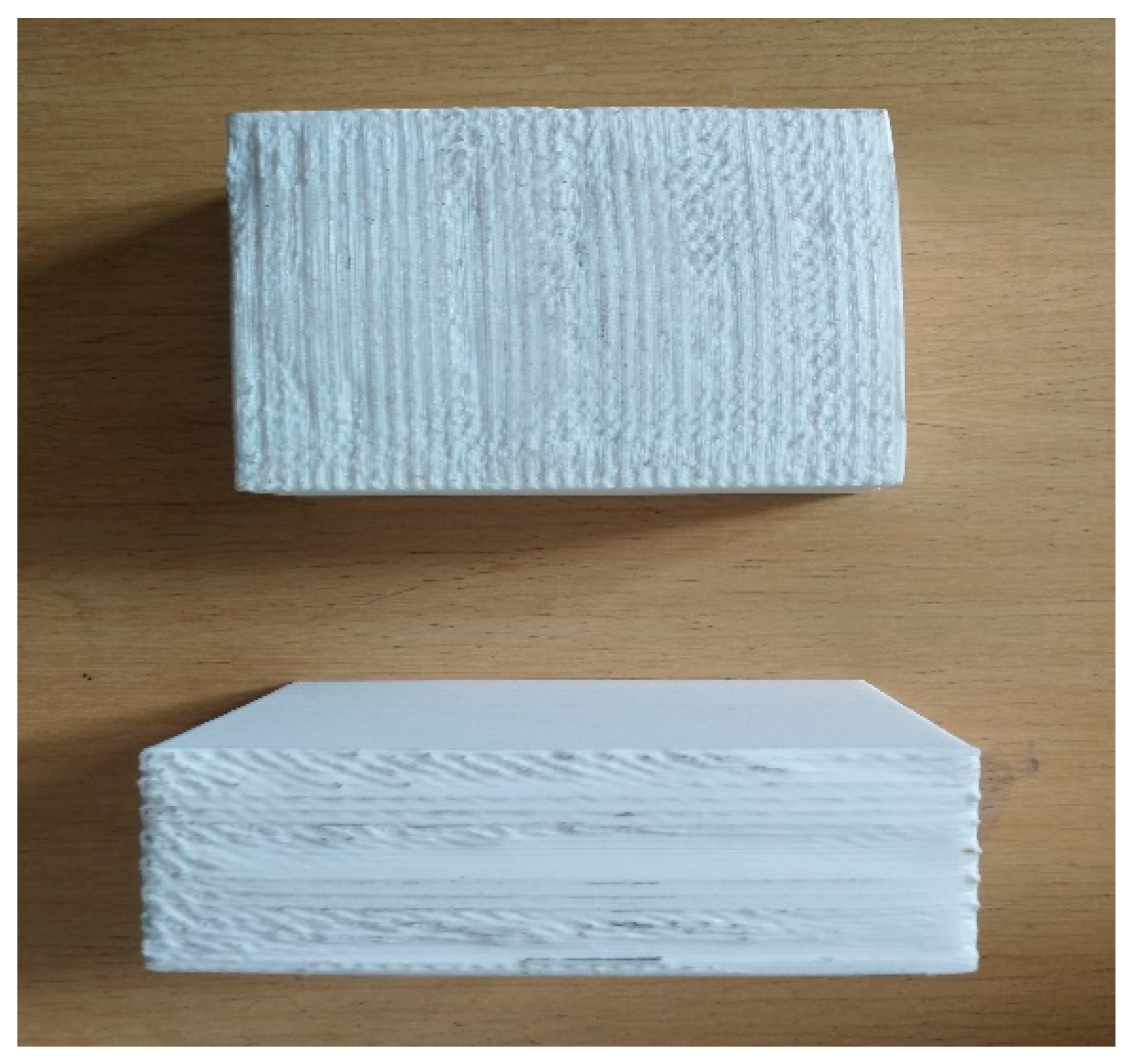
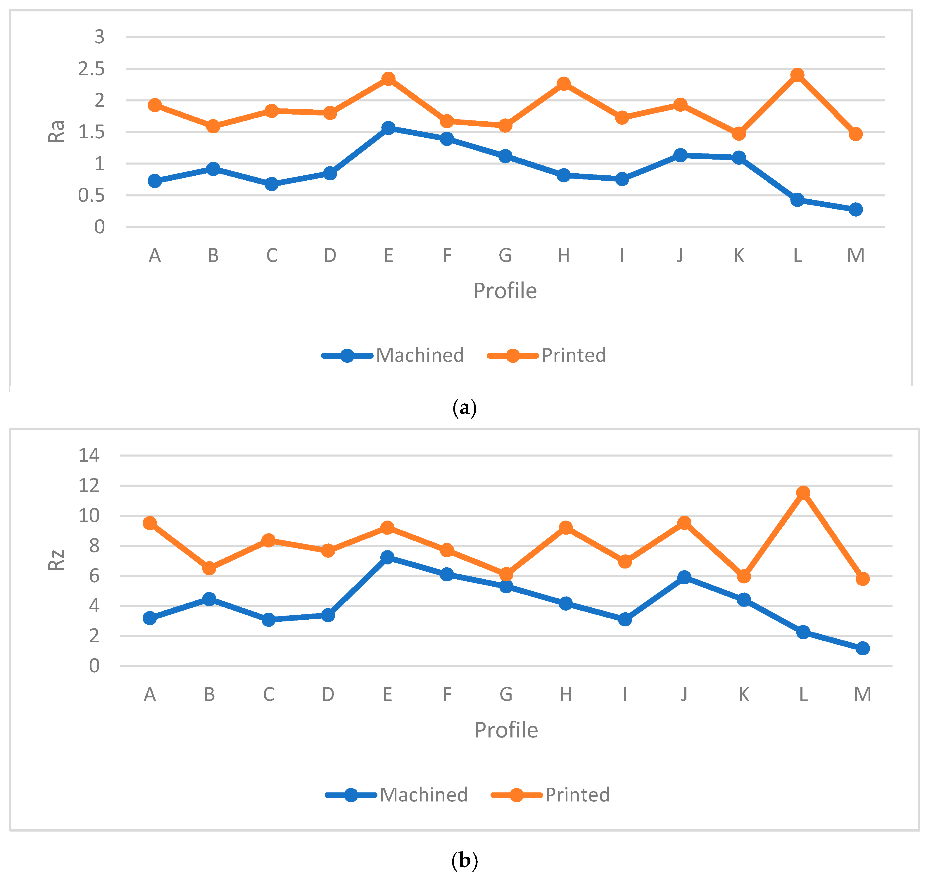
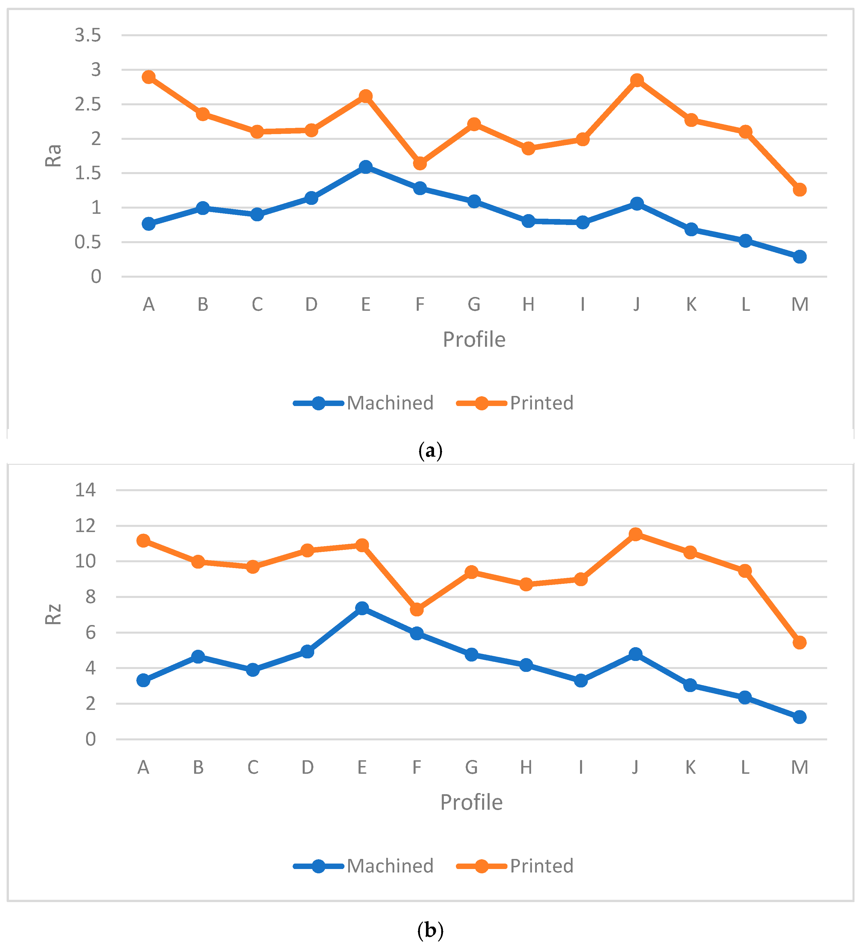
4.2. Comparison between Printed and Machined Samples
5. Conclusions
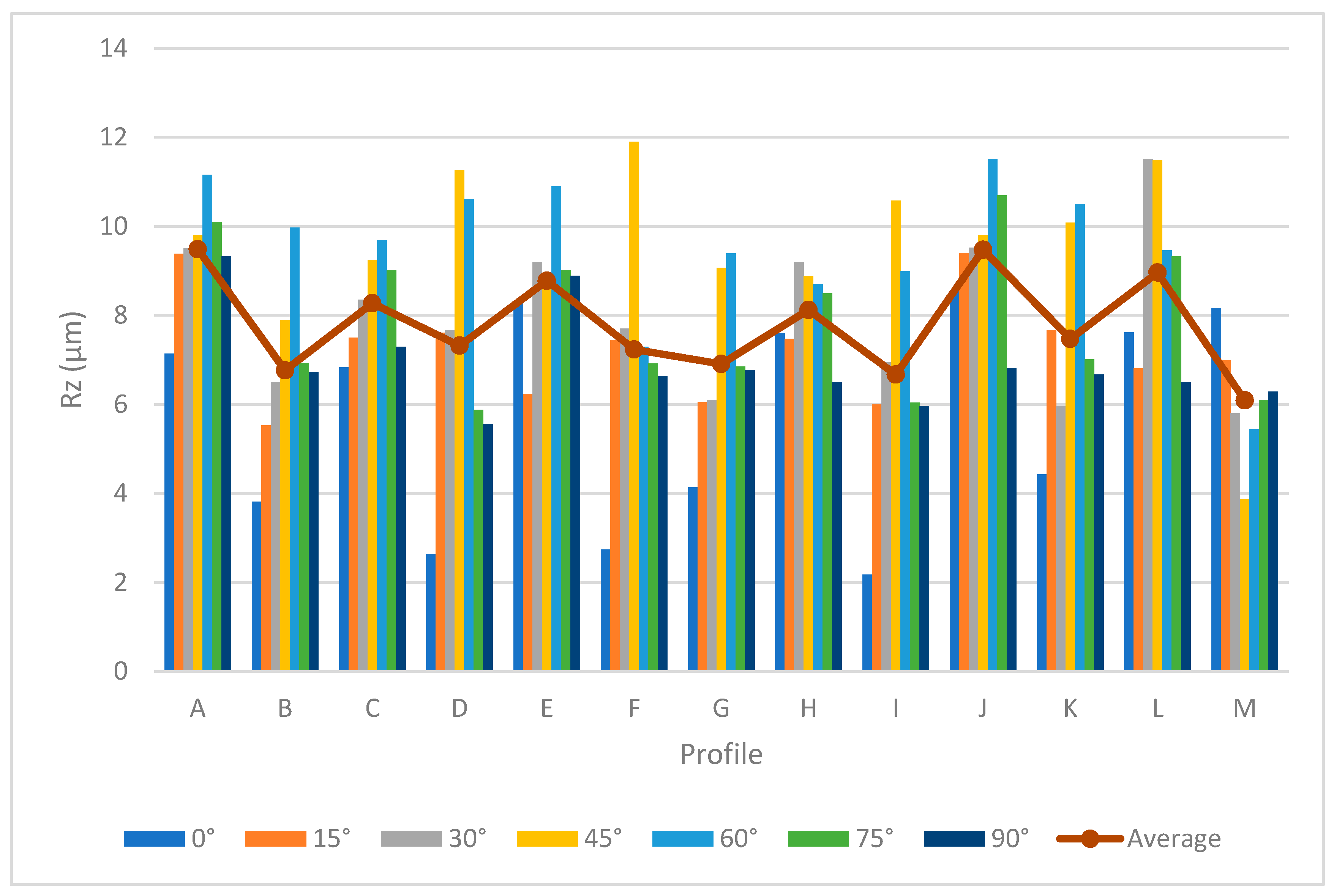
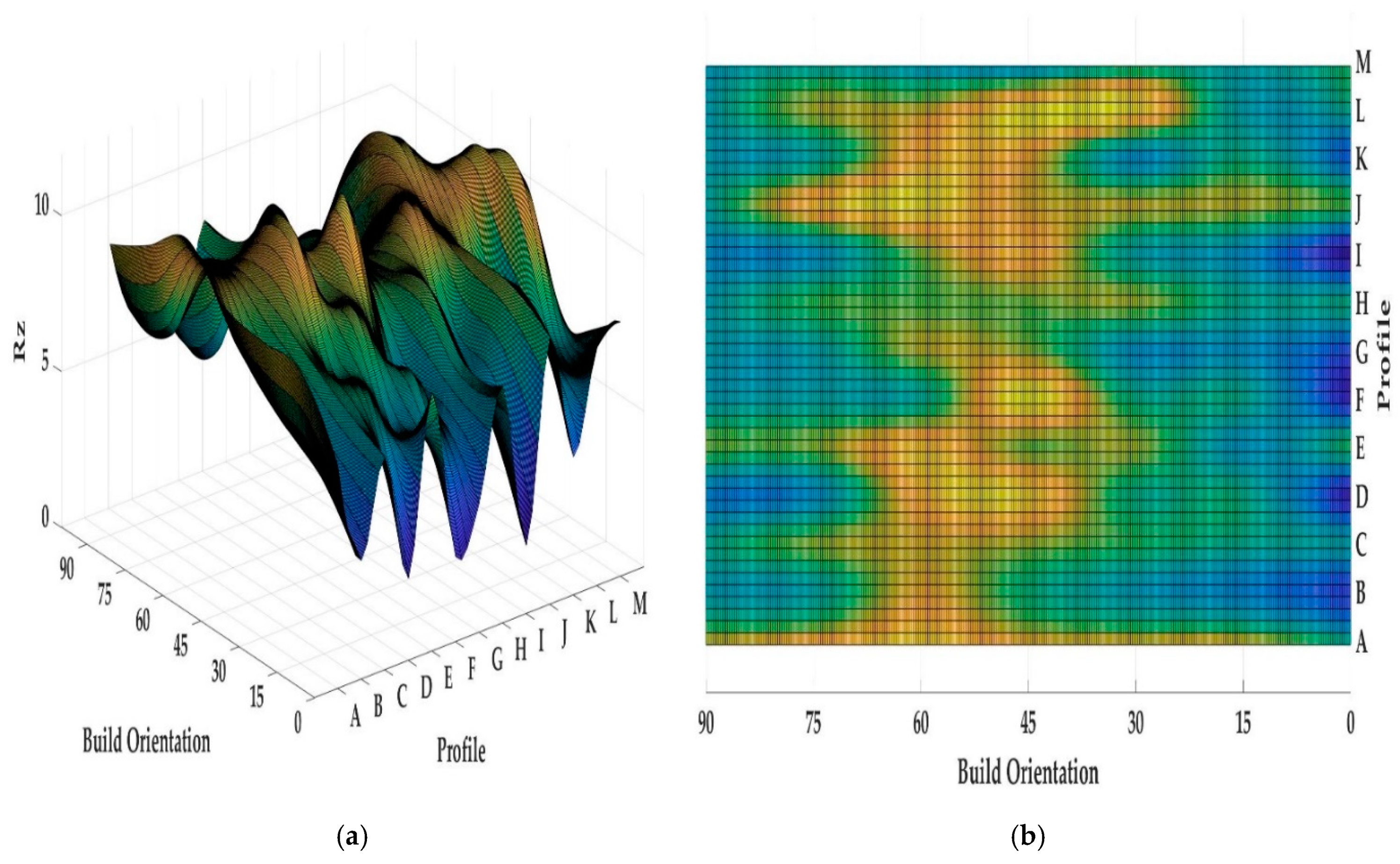
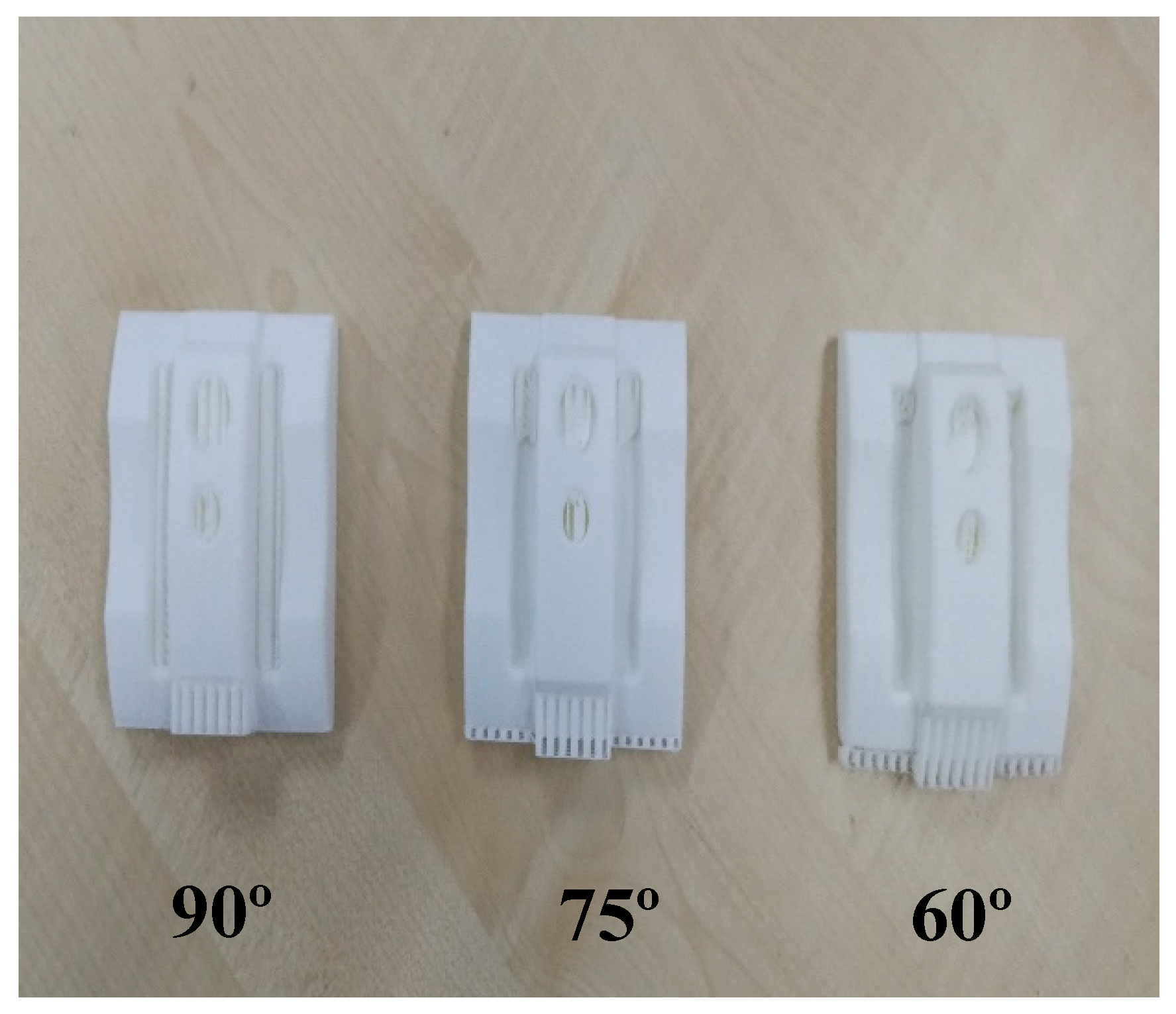
- The main aim of this study was to identify the effect of machining 3D printed samples in different build orientations, where it was found that orientation had a great impact on surface roughness.
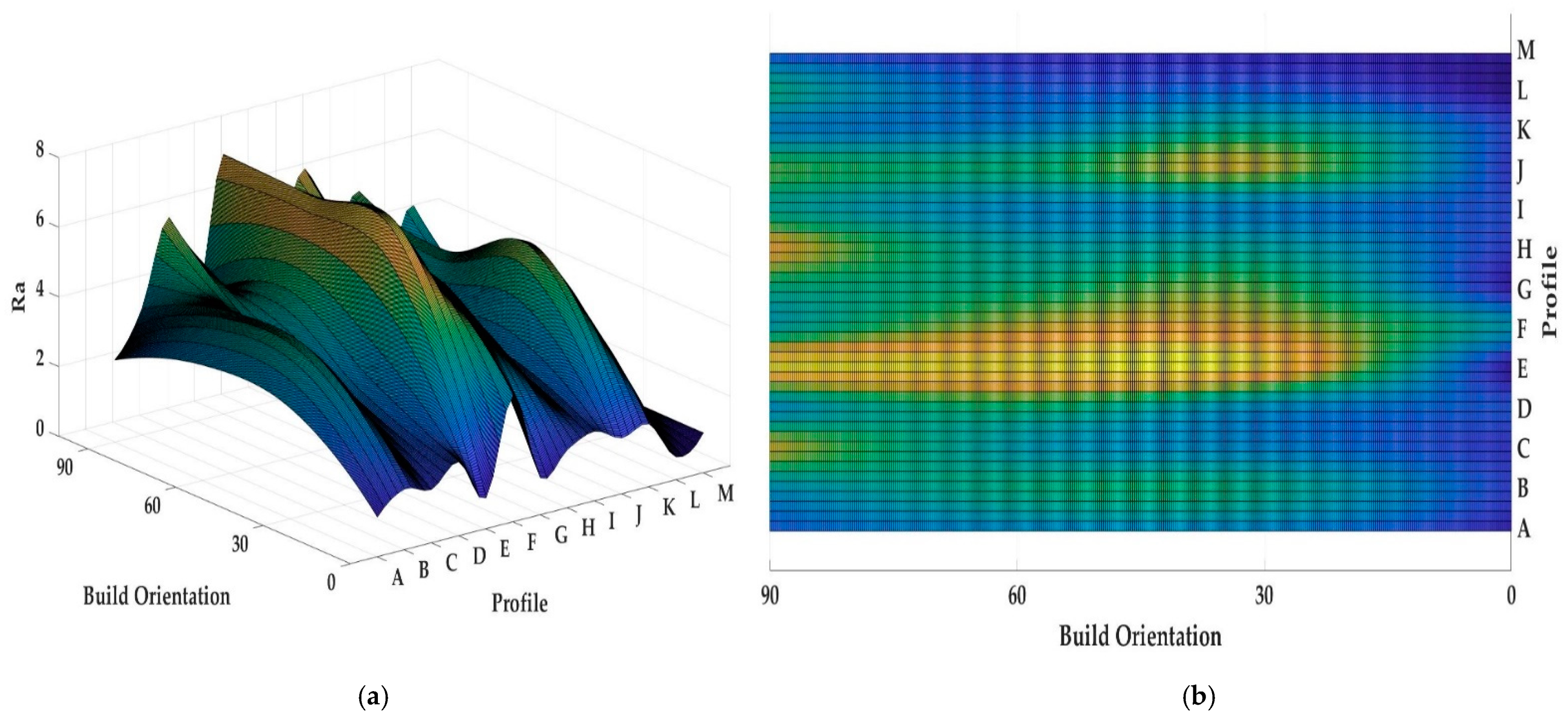
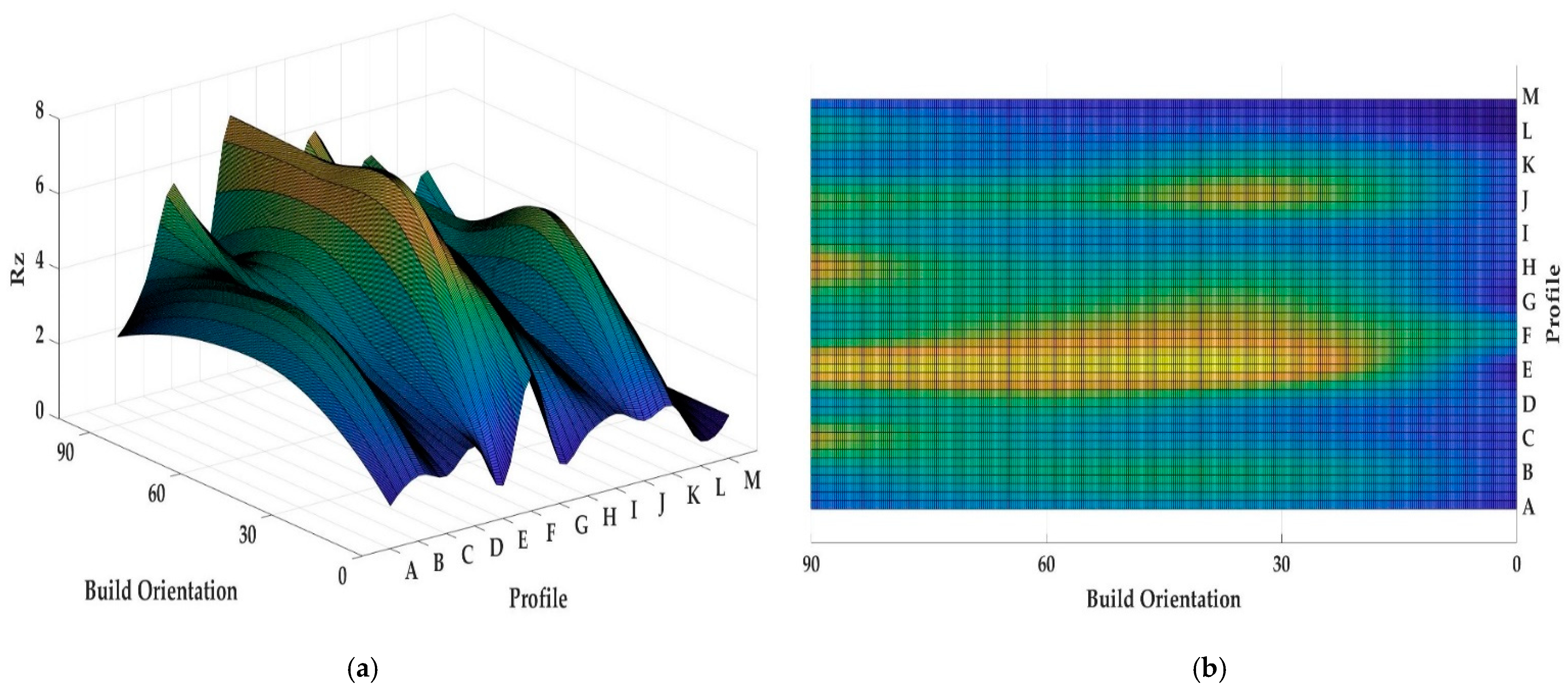
- In this case, the roughness was highest in perpendicular such as 60° sample, and then it started to decrease gradually.
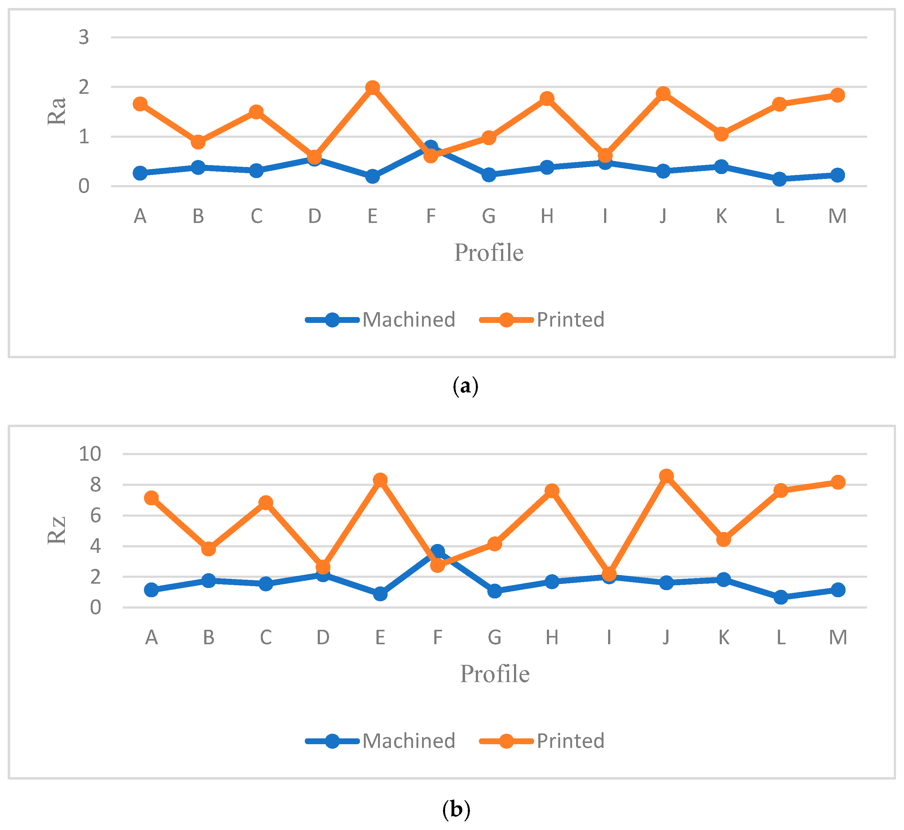
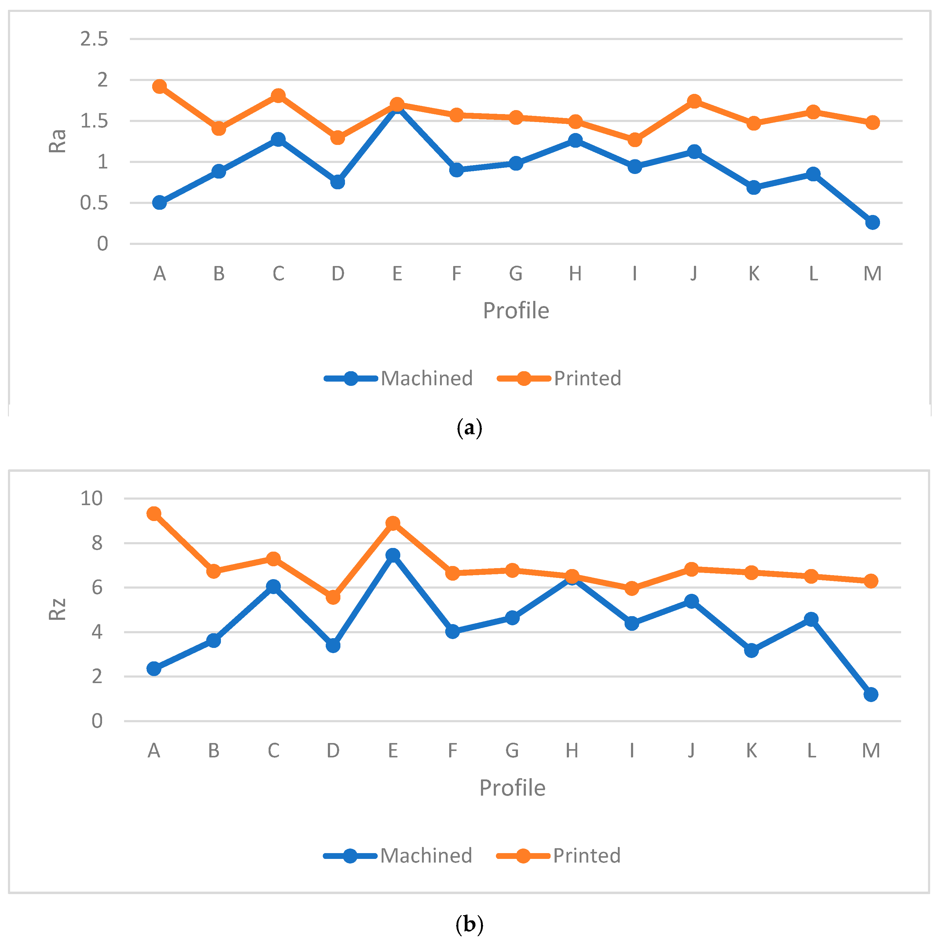
- Machining had an extraordinary effect on surface roughness in which its samples had better surface quality compared to printed ones.
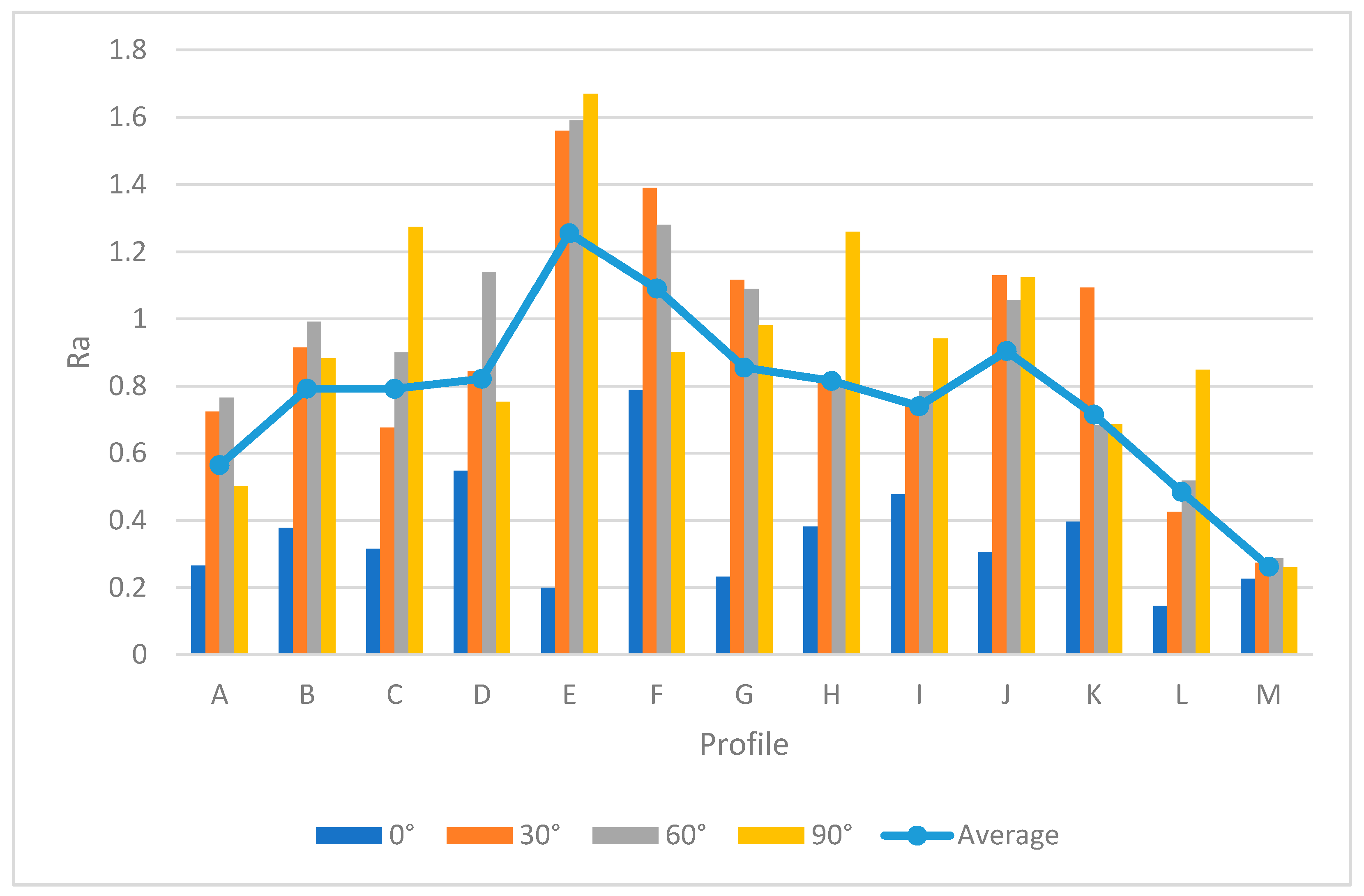
- The results showed 0° sample had the best surface quality between both processes. The average values of Ra and Rz in profile for 0° specimen were 0.0690 µm and 3.294 µm in printed blocks, 1.293 µm and 5.7 µm in printed complex samples, and 0.358 µm and 1.622 µm in machined samples, respectively.
- Sample with 90° orientation showed a higher Ra value compared to other machined samples due to the different printing and machining orientation as discussed before.
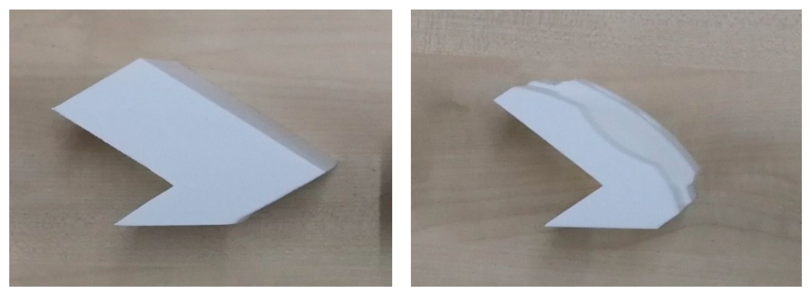
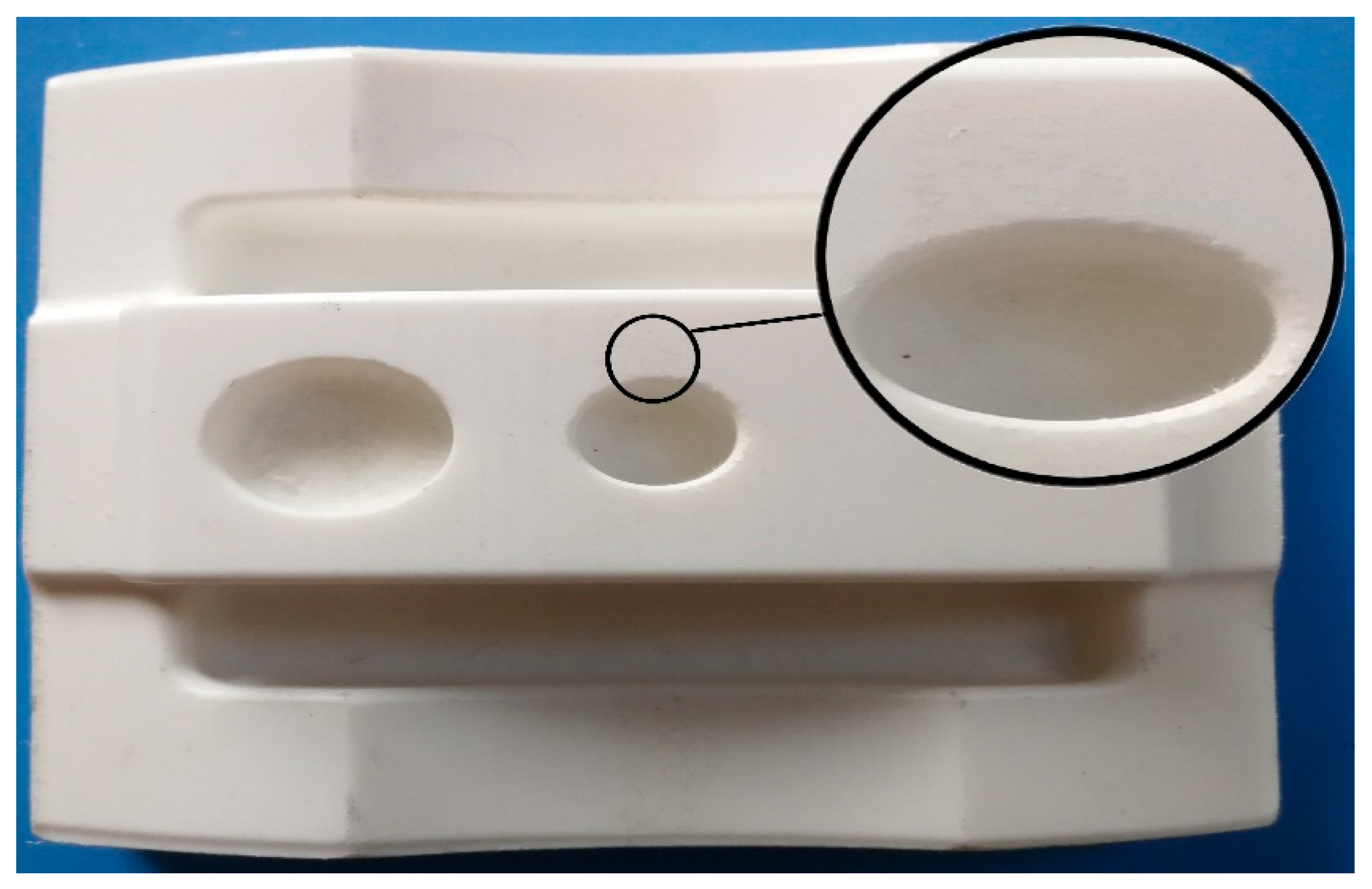
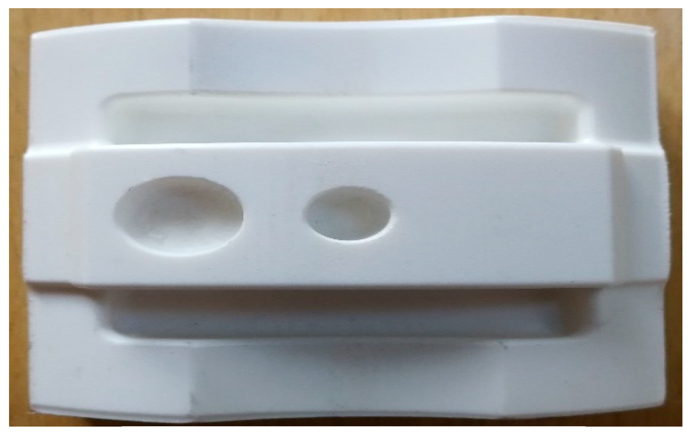
- Shattered materials were found on machined samples surface after finishing process. Surfaces were affected due to the defects. A poor feed rate or cutting speed may cause this issue. It is recommended to find out the best machining parameters in the finishing process to eliminate this issue for further researches.
- Holes in machining samples had the worst surface quality in this case due to the defect that is mentioned.
- In machining process, profile M had the best surface quality. It means the machining parameters were suitable for side milling which lead to better surface.
- Besides, this study showed that the surface roughness was better at certain angles than others, implying that one could improve the surface quality of the parts intended for 3D printing.
- It should be noticed, the flat surfaces had better surface quality compared to slippery profiles.
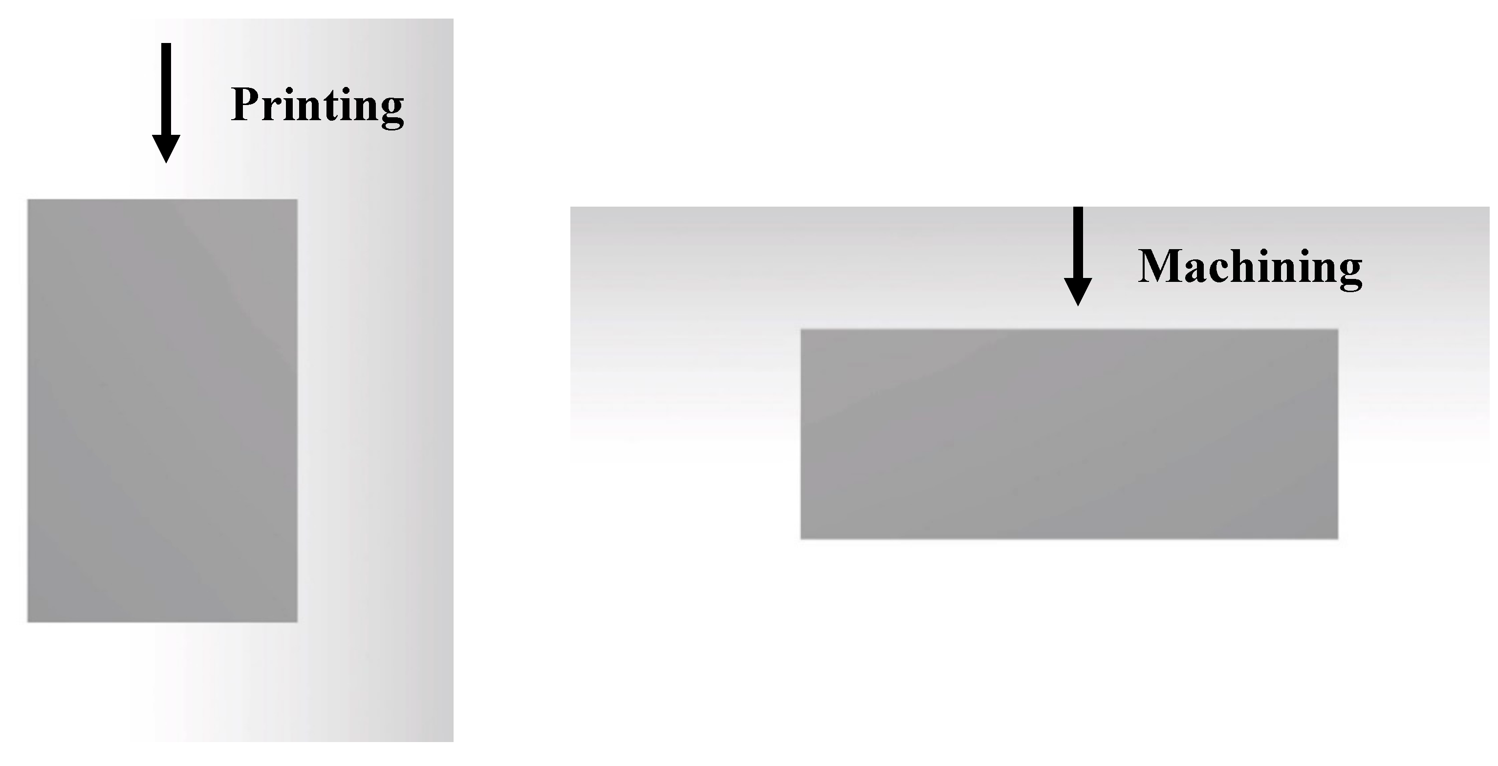
- By changing the build orientation, the slope surfaces are changed as well. This means that if the angle and orientation are aligned, the surface quality becomes better.
- This study could be used as a guideline for the users of 3D printers requiring sample machining as a second process for better surface quality in different applications such as automotive, medical, and consumer products manufacturing which need good functional and tolerances. As a secondary process, CNC machining provides additional dimensional accuracy with tighter tolerances on additive parts while maintaining all the benefits of FDM. Popular applications, in this case, are jigs and fixtures which are made by FDM with light weight and ergonomically. Depending on the complexity of the jig or fixture, CNC machining is needed to line bore parts for alignment, face mill for smooth surfaces, or machine complementary metal parts. Another application is when products require complementary metal or plastic parts in different materials. This can be done by attaching machined plastic parts to the incomplete sample by pausing the FDM process to make an assembly product. Furthermore, hybrid manufacturing can be another application which is used FDM and CNC machining simultaneously.
- Nevertheless, a lot of work is required and an expansive room for research is present in the field of FDM surface analysis. For example, no focus has been placed on layer thickness and its effects in the machining process. Therefore, future works can opt for samples that are 3D printed at different layer thicknesses to determine the effect on the surface roughness in the machining process. Moreover, different materials should be tested and analysed. The influence of different parameters in finishing machining and how they affect the surface can also be investigated in future studies.
Author Contributions
Funding
Acknowledgments
Conflicts of Interest
References
- Bralla, J.G. Design for Manufacturability Handbook; McGraw-Hill: New York, NY, USA, 1999; Chapter 9; pp. 3–33. [Google Scholar]
- Kalpakjian, S. Manufacturing Engineering and Technology; Pearson Education: London, UK, 2009. [Google Scholar]
- Ghaffar, S.H.; Corker, J.; Fan, M. Additive manufacturing technology and its implementation in construction as an eco-innovative solution. Autom. Constr. 2018, 93, 1–11. [Google Scholar] [CrossRef]
- Bose, S.; Ke, D.; Sahasrabudhe, H.; Bandyopadhyay, A. Additive manufacturing of biomaterials. Prog. Mater. Sci. 2018, 93, 45–111. [Google Scholar] [CrossRef]
- Goh, G.; Agarwala, S.; Dikshit, V.; Sing, S.; Yeong, W.Y.; Goh, G. Additive manufacturing in unmanned aerial vehicles (UAVs): Challenges and potential. Aerosp. Sci. Technol. 2017, 63, 140–151. [Google Scholar] [CrossRef]
- Cuellar, J.; Smit, G.; Plettenburg, D.; Zadpoor, A. Additive manufacturing of non-assembly mechanisms. Addit. Manuf. 2018, 21, 150–158. [Google Scholar] [CrossRef]
- Calignano, F.; Manfredi, D.; Ambrosio, E.P.; Biamino, S.; Lombardi, M.; Atzeni, E.; Salmi, A.; Minetola, P.; Iuliano, L.; Fino, P. Overview on Additive Manufacturing Technologies. Proc. IEEE 2017, 105, 593–612. [Google Scholar] [CrossRef]
- Francois, M.; Sun, A.; King, W.; Henson, N.; Tourret, D.; Bronkhorst, C.; Carlson, N.; Newman, C.; Haut, T.; Bakosi, J.; et al. Modeling of additive manufacturing processes for metals: Challenges and opportunities. Curr. Opin. Solid State Mater. Sci. 2017, 21, 198–206. [Google Scholar] [CrossRef]
- Boparai, K.S.; Singh, R.; Singh, H. Development of rapid tooling using fused deposition modeling: A review. Rapid Prototyp. J. 2016, 22, 281–299. [Google Scholar] [CrossRef]
- Marwah, O.; Sharif, S.; Ibrahim, M.; Mohamad, E.; Idris, M. Direct rapid prototyping evaluation on multijet and fused deposition modeling patterns for investment casting. Proc. Inst. Mech. Eng. Part L J. Mater. Des. Appl. 2016, 230, 949–958. [Google Scholar] [CrossRef]
- Gebhardt, A. Hötter, J.-S. 4—Rapid Prototyping. In Additive Manufacturing; Hanser Publications: Cincinnati, OH, USA, 2016; pp. 291–352. [Google Scholar]
- Pham, D.T.; Gault, R. A comparison of rapid prototyping technologies. Int. J. Mach. Tools Manuf. 1998, 38, 1257–1287. [Google Scholar] [CrossRef]
- Ariffin, M.K.A.M.; Sukindar, N.A.; Baharudin, B.H.T.; A Jaafar, C.N.; Ismail, M.I.S. Slicer Method Comparison Using Open-source 3D Printer. In Proceedings of the IOP Conference Series: Earth and Environmental Science, Ottawa, ON, Canada, 13–15 September 2017; IOP Publishing: Philadelphia, PA, USA, 2018; Volume 114, p. 12018. [Google Scholar]
- Ngo, T.; Kashani, A.; Imbalzano, G.; Nguyen, Q.T.; Hui, D. Additive manufacturing (3D printing): A review of materials, methods, applications and challenges. Compos. Part B: Eng. 2018, 143, 172–196. [Google Scholar] [CrossRef]
- Chia, H.N.; Wu, B.M. Recent advances in 3D printing of biomaterials. J. Boil. Eng. 2015, 9, 4. [Google Scholar] [CrossRef] [PubMed] [Green Version]
- Frazier, W.E. Metal Additive Manufacturing: A Review. J. Mater. Eng. Perform. 2014, 23, 1917–1928. [Google Scholar] [CrossRef]
- Gibson, I.; Rosen, D.W.; Stucker, B. Additive Manufacturing Technologies; Springer: Boston, MA, USA, 2014. [Google Scholar]
- Wong, K.V.; Hernandez, A. A Review of Additive Manufacturing. ISRN Mech. Eng. 2012, 2012, 1–10. [Google Scholar] [CrossRef] [Green Version]
- Panda, B.; Shankhwar, K.; Garg, A.; Jian, Z. Performance evaluation of warping characteristic of fused deposition modelling process. Int. J. Adv. Manuf. Technol. 2016, 88, 1799–1811. [Google Scholar] [CrossRef]
- Matsuzaki, R.; Ueda, M.; Namiki, M.; Jeong, T.-K.; Asahara, H.; Horiguchi, K.; Nakamura, T.; Todoroki, A.; Hirano, Y. Three-dimensional printing of continuous-fiber composites by in-nozzle impregnation. Sci. Rep. 2016, 6, 23058. [Google Scholar] [CrossRef]
- Ning, F.; Cong, W.; Qiu, J.; Wei, J.; Wang, S. Additive manufacturing of carbon fiber reinforced thermoplastic composites using fused deposition modeling. Compos. Part B Eng. 2015, 80, 369–378. [Google Scholar] [CrossRef]
- Dul, S.; Fambri, L.; Pegoretti, A. Fused deposition modelling with ABS–graphene nanocomposites. Compos. Part A Appl. Sci. Manuf. 2016, 85, 181–191. [Google Scholar] [CrossRef]
- Panda, B.; Unluer, C.; Tan, M.J. Investigation of the rheology and strength of geopolymer mixtures for extrusion-based 3D printing. Cem. Concr. Compos. 2018, 94, 307–314. [Google Scholar] [CrossRef]
- Jabbari, A.; Abrinia, K. Developing thixo-extrusion process for additive manufacturing of metals in semi-solid state. J. Manuf. Process 2018, 35, 664–671. [Google Scholar] [CrossRef]
- Hsieh, P.C.; Tsai, C.H.; Liu, B.H.; Wei, W.C.J.; Wang, A.B.; Luo, R.C. 3D printing of low melting temperature alloys by fused deposition modeling. In Proceedings of the 2016 IEEE International Conference on Industrial Technology (ICIT), Taipei, Taiwan, 14–17 March 2016; Institute of Electrical and Electronics Engineers (IEEE): Piscataway, NJ, USA, 2016; pp. 1138–1142. [Google Scholar]
- Le Duigou, A.; Castro, M.; Bevan, R.; Martin, N. 3D printing of wood fibre biocomposites: From mechanical to actuation functionality. Mater. Des. 2016, 96, 106–114. [Google Scholar] [CrossRef]
- Kruth, J.-P.; Leu, M.; Nakagawa, T. Progress in Additive Manufacturing and Rapid Prototyping. CIRP Ann. 1998, 47, 525–540. [Google Scholar] [CrossRef]
- Kuo, C.-C.; Wu, Y.-R.; Li, M.-H.; Wu, H.-W. Minimizing warpage of ABS prototypes built with low-cost fused deposition modeling machine using developed closed-chamber and optimal process parameters. Int. J. Adv. Manuf. Technol. 2018, 101, 593–602. [Google Scholar] [CrossRef]
- Alsoufi, M.; El-Sayed, A. Warping Deformation of Desktop 3D Printed Parts Manufactured by Open Source Fused Deposition Modeling (FDM) System. Int. J. Mech. Mechatron. Eng. 2017, 17, 7–16. [Google Scholar]
- Bourell, D.; Kruth, J.P.; Leu, M.; Levy, G.; Rosen, D.; Beese, A.M.; Clare, A. Materials for additive manufacturing. CIRP Annals 2017, 66, 659–681. [Google Scholar] [CrossRef]
- Choi, J.-W.; Medina, F.; Kim, C.; Espalin, D.; Rodríguez, D.; Stucker, B.; Wicker, R. Development of a mobile fused deposition modeling system with enhanced manufacturing flexibility. J. Mater. Process. Technol. 2011, 211, 424–432. [Google Scholar] [CrossRef]
- Wulle, F.; Coupek, D.; Schäffner, F.; Verl, A.; Oberhofer, F.; Maier, T. Workpiece and Machine Design in Additive Manufacturing for Multi-Axis Fused Deposition Modeling. Procedia CIRP 2017, 60, 229–234. [Google Scholar] [CrossRef]
- Isa, M.A.; Lazoglu, I. Five-axis additive manufacturing of freeform models through buildup of transition layers. J. Manuf. Syst. 2019, 50, 69–80. [Google Scholar] [CrossRef]
- Faludi, J.; Bayley, C.; Bhogal, S.; Iribarne, M. Comparing environmental impacts of additive manufacturing vs traditional machining via life-cycle assessment. Rapid Prototyp. J. 2015, 21, 14–33. [Google Scholar] [CrossRef] [Green Version]
- Yan, Q.; Dong, H.-H.; Su, J.; Han, J.; Song, B.; Wei, Q.; Shi, Y. A Review of 3D Printing Technology for Medical Applications. Engineering 2018, 4, 729–742. [Google Scholar] [CrossRef]
- Domingo-Espin, M.; Puigoriol-Forcada, J.M.; García-Granada, A.A.; Llumà, J.; Borrós, S.; Reyes, G. Mechanical property characterization and simulation of fused deposition modeling Polycarbonate parts. Mater. Des. 2015, 83, 670–677. [Google Scholar] [CrossRef]
- Zhao, J.; Zhang, M.; Zhu, Y.; Li, X.; Wang, L. A Novel Optimization Design Method of Additive Manufacturing Oriented Porous Structures. In Proceedings of the ASME 2018 International Mechanical Engineering Congress and Exposition, Pittsburgh, PA, USA, 9–15 November 2018; ASME: New York, NY, USA, 2018. [Google Scholar] [CrossRef]
- McCullough, E.J.; Yadavalli, V.K. Surface modification of fused deposition modeling ABS to enable rapid prototyping of biomedical microdevices. J. Mater. Process. Technol. 2013, 213, 947–954. [Google Scholar] [CrossRef]
- Alauddin, M.; Choudhury, I.; El Baradie, M.; Hashmi, M. Plastics and their machining: A review. J. Mater. Process. Technol. 1995, 54, 40–46. [Google Scholar] [CrossRef]
- Salmi, M.; Ituarte, I.F.; Chekurov, S.; Huotilainen, E. Effect of build orientation in 3D printing production for material extrusion, material jetting, binder jetting, sheet object lamination, vat photopolymerisation, and powder bed fusion. Int. J. of Collab. Enterp. 2016, 5, 218–231. [Google Scholar] [CrossRef]
- Peng, T.; Xu, X. Energy-efficient machining systems: A critical review. Int. J. Adv. Manuf. Technol. 2014, 72, 1389–1406. [Google Scholar] [CrossRef]
- Song, H.-C.; Ray, N.; Sokolov, D.; Lefebvre, S. Anti-aliasing for fused filament deposition. Comput. Des. 2017, 89, 25–34. [Google Scholar] [CrossRef] [Green Version]
- Benardos, P.; Vosniakos, G.-C. Predicting surface roughness in machining: A review. Int. J. Mach. Tools Manuf. 2003, 43, 833–844. [Google Scholar] [CrossRef]
- Caggiano, A. Machining of Fibre Reinforced Plastic Composite Materials. Materials 2018, 11, 442. [Google Scholar] [CrossRef] [Green Version]
- Hsu, T.-K.; Zeren, E. Effects of cutting edge geometry, workpiece hardness, feed rate and cutting speed on surface roughness and forces in finish turning of hardened AISI H13 steel. Int. J. Adv. Manuf. Technol. 2004, 25, 262–269. [Google Scholar] [CrossRef]
- Bhushan, B. Surface Roughness Analysis and Measurement Techniques. In Modern Tribology Handbook, Two Volume Set; Informa UK Limited: London, UK, 2000; Volume 5, pp. 79–150. [Google Scholar]
- Black, J.T.; Kohser, R.A.; DeGarmo, E.P. DeGarmo’s Materials and Processes in Manufacturing; Wiley: Hoboken, NJ, USA, 2017. [Google Scholar]
- Taufik, M.; Jain, P.K. A Study of Build Edge Profile for Prediction of Surface Roughness in Fused Deposition Modeling. J. Manuf. Sci. Eng. 2016, 138, 061002. [Google Scholar] [CrossRef]
- Henerichs, M.; Voß, R.; Küster, F.; Wegener, K. Machining of carbon fiber reinforced plastics: Influence of tool geometry and fiber orientation on the machining forces. CIRP J. Manuf. Sci. Technol. 2015, 9, 136–145. [Google Scholar] [CrossRef]
- Taufik, M.; Jain, P.K. Laser assisted finishing process for improved surface finish of fused deposition modelled parts. J. Manuf. Process 2017, 30, 161–177. [Google Scholar] [CrossRef]
- Leach, R. Characterisation of Areal Surface Texture; Springer: Berlin/Heidelberg, Germany, 2013. [Google Scholar]
- Sauri, J.; Suñé-Negre, J.; Diaz, J.; Vilana, J.; Millan, D.; Ticó, J.; Miñarro, M.; Pérez-Lozano, P.; García-Montoya, E. Relationships between surface free energy, surface texture parameters and controlled drug release in hydrophilic matrices. Int. J. Pharm. 2015, 478, 328–340. [Google Scholar] [CrossRef] [PubMed]
- Ali, F.; Chowdary, B.V.; Maharaj, J. Influence of some process parameters on build time, material consumption, and surface roughness of FDM processed parts: Inferences based on the Taguchi design of experiments. In Proceedings of the 2014 IACJ/ISAM Joint International Conference, Orlando, FL, USA, 25–27 September 2014; International Journal of Modern Engineering: Northridge, CA, USA, 2014. [Google Scholar]
- Dey, A.; Yodo, N. A Systematic Survey of FDM Process Parameter Optimization and Their Influence on Part Characteristics. J. Manuf. Mater. Process. 2019, 3, 64. [Google Scholar] [CrossRef] [Green Version]
- Khan, M.S.; Dash, J.P. Enhancing Surface Finish of Fused Deposition Modelling Parts. In 3D Printing and Additive Manufacturing Technologies; Springer: Singapore, 2018; pp. 45–57. [Google Scholar]
- Chen, Y.-F.; Wang, Y.-H.; Tsai, J.-C. Enhancement of surface reflectivity of fused deposition modeling parts by post-processing. Opt. Commun. 2019, 430, 479–485. [Google Scholar] [CrossRef]
- Adel, M.; Abdelaal, O.; Gad, A.; Nasr, A.B.; Khalil, A. Polishing of fused deposition modeling products by hot air jet: Evaluation of surface roughness. J. Mater. Process. Technol. 2018, 251, 73–82. [Google Scholar] [CrossRef]
- Thrimurthulu, K.; Pandey, P.M.; Reddy, N.V. Optimum part deposition orientation in fused deposition modeling. Int. J. Mach. Tools Manuf. 2004, 44, 585–594. [Google Scholar] [CrossRef]
- Bellini, A.; Güçeri, S. Mechanical characterization of parts fabricated using fused deposition modeling. Rapid Prototyp. J. 2003, 9, 252–264. [Google Scholar] [CrossRef]
- Boschetto, A.; Bottini, L. Accuracy prediction in fused deposition modeling. Int. J. Adv. Manuf. Technol. 2014, 73, 913–928. [Google Scholar] [CrossRef]
- Ahn, D.; Kweon, J.-H.; Kwon, S.-M.; Song, J.; Lee, S. Representation of surface roughness in fused deposition modeling. J. Mater. Process. Technol. 2009, 209, 5593–5600. [Google Scholar] [CrossRef]
- Durgun, I.; Ertan, R. Experimental investigation of FDM process for improvement of mechanical properties and production cost. Rapid Prototyp. J. 2014, 20, 228–235. [Google Scholar] [CrossRef]
- Zhang, Y.; Chou, K. A parametric study of part distortions in fused deposition modelling using three-dimensional finite element analysis. Proc. Inst. Mech. Eng. Part B J. Eng. Manuf. 2008, 222, 959–968. [Google Scholar] [CrossRef]
- Salonitis, K.; D’Alvise, L.; Schoinochoritis, B.; Chantzis, D. Additive manufacturing and post-processing simulation: Laser cladding followed by high speed machining. Int. J. Adv. Manuf. Technol. 2015, 85, 2401–2411. [Google Scholar] [CrossRef]
- Hällgren, S.; Pejryd, L.; Ekengren, J. Additive Manufacturing and High Speed Machining -cost Comparison of short Lead Time Manufacturing Methods. Procedia CIRP 2016, 50, 384–389. [Google Scholar] [CrossRef] [Green Version]
- Kumbhar, N.N.; Mulay, A.V. Post Processing Methods used to Improve Surface Finish of Products which are Manufactured by Additive Manufacturing Technologies: A Review. J. Inst. Eng. India Ser. C 2016, 99, 481–487. [Google Scholar] [CrossRef]
- Pandey, P.M.; Reddy, N.V.; Dhande, S.G. Improvement of surface finish by staircase machining in fused deposition modeling. J. Mater. Process. Technol. 2003, 132, 323–331. [Google Scholar] [CrossRef]
- Boschetto, A.; Bottini, L.; Veniali, F. Finishing of Fused Deposition Modeling parts by CNC machining. Robot. Comput. Manuf. 2016, 41, 92–101. [Google Scholar] [CrossRef]
- Chohan, J.S.; Singh, R. Pre and post processing techniques to improve surface characteristics of FDM parts: A state of art review and future applications. Rapid Prototyp. J. 2017, 23, 495–513. [Google Scholar] [CrossRef]
- Shukor, J.A.; Said, S.; Harun, R.; Husin, S.; Kadir, A. Optimising of machining parameters of plastic material using Taguchi method. Adv. Mater. Process. Technol. 2016, 2, 50–56. [Google Scholar] [CrossRef]
- Dhokia, V.; Kumar, S.; Vichare, P.; Newman, S.; Allen, R.D. Surface roughness prediction model for CNC machining of polypropylene. Proc. Inst. Mech. Eng. Part B J. Eng. Manuf. 2008, 222, 137–157. [Google Scholar] [CrossRef]
- Raju, K.V.M.K.; Janardhana, G.R.; Kumar, P.N.; Rao, V.D.P. Optimization of cutting conditions for surface roughness in CNC end milling. Int. J. Precis. Eng. Manuf. 2011, 12, 383–391. [Google Scholar] [CrossRef]
- Pămărac, R.G.; Petruse, R.E. Study Regarding the Optimal Milling Parameters for Finishing 3D Printed Parts from ABS and PLA Materials. Acta Univ. Cibiniensis 2018, 70, 66–72. [Google Scholar] [CrossRef] [Green Version]
- Prakasvudhisarn, C.; Kunnapapdeelert, S.; Yenradee, P. Optimal cutting condition determination for desired surface roughness in end milling. Int. J. Adv. Manuf. Technol. 2008, 41, 440–451. [Google Scholar] [CrossRef]
- Taufik, M.; Jain, P.K. CNC-assisted selective melting for improved surface finish of FDM parts. Taylor Fr. J. Virtual Phys. Prototyp. 2016, 11, 319–341. [Google Scholar] [CrossRef]
- Krolczyk, G.; Raos, P.; Legutko, S. Experimental analysis of surface roughness and surface texture of machined and fused deposition modelled parts. Tehnicki Vjesnik 2014, 21, 217–221. [Google Scholar]
- Pérez, M.; Medina-Sanchez, G.; Collado, A.G.; Gupta, M.K.; Carou, D. Surface Quality Enhancement of Fused Deposition Modeling (FDM) Printed Samples Based on the Selection of Critical Printing Parameters. Materials 2018, 11, 1382. [Google Scholar] [CrossRef] [PubMed] [Green Version]
- Taufik, M.; Jain, P.K. Role of build orientation in layered manufacturing: A review. Int. J. Manuf. Technol. Manag. 2013, 27, 47. [Google Scholar] [CrossRef]
- Pandey, P.M.; Thrimurthulu, K. Optimal part deposition orientation in FDM by using a multicriteria genetic algorithm. Int. J. Prod. Res. 2004, 42, 4069–4089. [Google Scholar] [CrossRef]
- Reddy, V.; Flys, O.; Chaparala, A.; Berrimi, C.E.; Amogh, V.; Rosen, B.G. Study on surface texture of Fused Deposition Modeling. Procedia Manuf. 2018, 25, 389–396. [Google Scholar] [CrossRef]
- Peng, T.; Yan, F. Dual-objective Analysis for Desktop FDM Printers: Energy Consumption and Surface Roughness. Procedia CIRP 2018, 69, 106–111. [Google Scholar] [CrossRef]
- Quinten, M. A Practical Guide to Surface Metrology. Psychological and Social Measurement; Springer International Publishing: Boston, MA, USA, 2019. [Google Scholar]
- Hyndhavi, D.; Babu, G.R.; Murthy, S.B. Investigation of Dimensional Accuracy and Material Performance in Fused Deposition Modeling. Mater. Today: Proc. 2018, 5, 23508–23517. [Google Scholar] [CrossRef]
- Armillotta, A.; Bellotti, M.; Cavallaro, M. Warpage of FDM parts: Experimental tests and analytic model. Robot. Comput. Manuf. 2018, 50, 140–152. [Google Scholar] [CrossRef]


| Parameter | Description | Equation |
|---|---|---|
| Ra | The arithmetical mean of the absolute values of Z(x) in a sampling length | |
| Rq | Root mean square average of the profile heights over the evaluation length | |
| Rsk | Skewness uses the cube of the root mean square deviation to display the dimensionless cube of the sampling length Z(x) | |
| Rku | The peaks of the profile (Zx) about the mean line | |
| Rv | The point along the sampling length at which the profile curve is lowest | |
| Rp | The maximum value of peak height Zp is a sampling length on the profile curve | |
| Rz | The absolute vertical distance between Rp and Rv along the sampling length |
| Machining Step | Process Type | Cutter (Ø) (mm) | Spindle Speed (rpm) | Cutting Speed (mm/min) | Feed Rate (mm/min) | Feed Per Tooth | Depth of Cut (mm) |
|---|---|---|---|---|---|---|---|
| 1 | End-mill | 12 | 4377 [73] | 165 [73] | 1000 [73] | 0.057 | 1 |
| 2 | End-mill | 5 | 3283 | 165 | 1000 | 0.057 | 1 |
| 3 | Finishing top | 5 Ball nose | 10,504 | 165 | 1000 | 0.057 | 1 |
| 4 | Finishing curves and pockets | 5 Ball nose | 10,504 | 165 | 1000 | 0.057 | 1 |
| 5 | Finishing holes and whole model | 6 Ball nose | 10,504 | 165 | 1000 | 0.057 | 1 |
| Aperiodic Profiles | Cut-off Wavelength | Evaluation Length | Tracing Length | |
|---|---|---|---|---|
| Rz (μm) | Ra (μm) | λc (mm) | Ln (mm) | Lt (mm) |
| <0.1 | <0.02 | 0.08 | 0.40 | 0.56 |
| 0.1–0.5 | 0.02–0.1 | 0.25 | 1.25 | 1.75 |
| 0.5–10 | 0.1–2 | 0.8 | 4.0 | 5.6 |
| 10–50 | 2–10 | 2.5 | 12.5 | 17.5 |
| >50 | >10 | 8 | 40 | 56 |
| Samples (BO) | Side | Ra (µm) | Rz (µm) | Samples (BO) | Side | Ra (µm) | Rz(µm) |
|---|---|---|---|---|---|---|---|
| 0° | A | 1.737 | 7.17 | 60° | A | 1.541 | 5.89 |
| B | 1.52 | 5.74 | B | 1.182 | 4.55 | ||
| C | 0.690 | 3.294 | C | 2.149 | 9.602 | ||
| 15° | A | 1.67 | 6.93 | 75° | A | 1.36 | 4.86 |
| B | 1.363 | 4.86 | B | 1.412 | 5.12 | ||
| C | 1.059 | 3.824 | C | 1.825 | 9.421 | ||
| 30° | A | 1.597 | 6.84 | 90° | A | 0.648 | 3.13 |
| B | 1.217 | 4.67 | B | 1.626 | 6.16 | ||
| C | 1.386 | 4.848 | C | 1.687 | 8.036 | ||
| 45° | A | 1.574 | 6.24 | – | – | – | – |
| B | 1.192 | 4.63 | – | – | – | – | |
| C | 1.633 | 6.32 | – | – | – | – |
| Sample (BO) | Profile | Ra (µm) | Rz (µm) | Sample (BO) | Profile | Ra (µm) | Ra (µm) |
|---|---|---|---|---|---|---|---|
| 0° | A | 1.660 | 7.14 | 30° | A | 1.923 | 9.5 |
| B | 0.891 | 3.81 | B | 1.589 | 6.50 | ||
| C | 1.498 | 6.83 | C | 1.832 | 8.35 | ||
| D | 0.587 | 2.63 | D | 1.799 | 7.67 | ||
| E | 1.986 | 8.30 | E | 2.340 | 9.20 | ||
| F | 0.611 | 2.74 | F | 1.670 | 7.70 | ||
| G | 0.977 | 4.14 | G | 1.600 | 6.10 | ||
| H | 1.766 | 7.6 | H | 2.26 | 9.2 | ||
| I | 0.620 | 2.18 | I | 1.725 | 6.94 | ||
| J | 1.865 | 8.56 | J | 1.93 | 9.52 | ||
| K | 1.053 | 4.43 | K | 1.470 | 5.96 | ||
| L | 1.653 | 7.62 | L | 2.40 | 11.52 | ||
| M | 1.834 | 8.16 | M | 1.467 | 5.80 | ||
| Average | 1.293 | 5.70 | Average | 1.846 | 7.99 | ||
| Std dev. | 0.55 | 2.41 | Std dev. | 0.32 | 1.74 | ||
| Variance | 0.3 | 5.82 | Variance | 0.1 | 3.01 | ||
| 15° | A | 1.832 | 9.38 | 45° | A | 2.039 | 9.8 |
| B | 1.24 | 5.53 | B | 2.200 | 7.89 | ||
| C | 1.647 | 7.50 | C | 1.971 | 9.25 | ||
| D | 1.732 | 7.61 | D | 2.591 | 11.27 | ||
| E | 1.398 | 6.24 | E | 1.873 | 8.90 | ||
| F | 1.600 | 7.45 | F | 2.770 | 11.90 | ||
| G | 1.371 | 6.05 | G | 2.190 | 9.07 | ||
| H | 1.529 | 7.47 | H | 2.038 | 8.88 | ||
| I | 1.504 | 6.00 | I | 2.543 | 10.58 | ||
| J | 1.890 | 9.40 | J | 2.433 | 9.8 | ||
| K | 1.486 | 7.66 | K | 2.2 | 10.08 | ||
| L | 1.418 | 6.81 | L | 2.388 | 11.49 | ||
| M | 1.607 | 6.99 | M | 1.034 | 3.87 | ||
| Average | 1.558 | 7.23 | Average | 2.174 | 9.44 | ||
| Std dev. | 0.19 | 1.18 | Std dev. | 0.43 | 2.04 | ||
| Variance | 0.03 | 1.40 | Variance | 0.19 | 4.15 | ||
| 60° | A | 2.894 | 11.16 | 90° | A | 1.919 | 9.32 |
| B | 2.356 | 9.97 | B | 1.406 | 6.73 | ||
| C | 2.100 | 9.69 | C | 1.808 | 7.29 | ||
| D | 2.122 | 10.61 | D | 1.293 | 5.56 | ||
| E | 2.617 | 10.90 | E | 1.70 | 8.89 | ||
| F | 1.642 | 7.29 | F | 1.57 | 6.64 | ||
| G | 2.210 | 9.39 | G | 1.540 | 6.77 | ||
| H | 1.859 | 8.7 | H | 1.490 | 6.50 | ||
| I | 1.990 | 8.99 | I | 1.268 | 5.96 | ||
| J | 2.849 | 11.52 | J | 1.738 | 6.82 | ||
| K | 2.269 | 10.5 | K | 1.470 | 6.67 | ||
| L | 2.1 | 9.46 | L | 1.608 | 6.50 | ||
| M | 1.260 | 5.44 | M | 1.478 | 6.29 | ||
| Average | 2.175 | 9.50 | Average | 1.56 | 6.91 | ||
| Std dev. | 0.45 | 1.67 | Std dev. | 0.19 | 1.06 | ||
| Variance | 0.21 | 2.80 | Variance | 0.04 | 1.13 | ||
| 75° | A | 2.36 | 10.1 | ||||
| B | 1.597 | 6.93 | |||||
| C | 1.883 | 9.01 | |||||
| D | 1.317 | 5.88 | |||||
| E | 1.990 | 9.02 | |||||
| F | 1.60 | 6.92 | |||||
| G | 1.630 | 6.85 | |||||
| H | 1.530 | 8.50 | |||||
| I | 1.32 | 6.04 | |||||
| J | 2.506 | 10.70 | |||||
| K | 1.54 | 7.01 | |||||
| L | 1.949 | 9.32 | |||||
| M | 1.44 | 6.85 | |||||
| Average | 2.174 | 7.87 | |||||
| Std dev. | 0.37 | 1.64 | |||||
| Variance | 0.14 | 2.68 |
| Sample (BO) | Profile | Ra (µm) | Rz (µm) | Sample (BO) | Profile | Ra (µm) | Rz (µm) |
|---|---|---|---|---|---|---|---|
| 0° | A | 0.265 | 1.145 | 60° | A | 0.765 | 3.31 |
| B | 0.378 | 1.75 | B | 0.992 | 4.64 | ||
| C | 0.315 | 1.54 | C | 0.9 | 3.9 | ||
| D | 0.548 | 2.13 | D | 1.139 | 4.93 | ||
| E | 0.199 | 0.89 | E | 1.59 | 7.36 | ||
| F | 0.789 | 3.65 | F | 1.28 | 5.95 | ||
| G | 0.232 | 1.07 | G | 1.09 | 4.76 | ||
| H | 0.382 | 1.68 | H | 0.804 | 4.17 | ||
| I | 0.478 | 2 | I | 0.785 | 3.3 | ||
| J | 0.306 | 1.61 | J | 1.056 | 4.78 | ||
| K | 0.396 | 1.814 | K | 0.683 | 3.04 | ||
| L | 0.145 | 0.66 | L | 0.519 | 2.35 | ||
| M | 0.226 | 1.15 | M | 0.287 | 1.25 | ||
| Average | 0.358 | 1.622 | Average | 0.914 | 4.13 | ||
| Std dev. | 0.17 | 0.75 | Std dev. | 0.34 | 1.57 | ||
| Variance | 0.03 | 0.57 | Variance | 0.12 | 2.46 | ||
| 30° | A | 0.724 | 3.185 | 90° | A | 0.502 | 2.35 |
| B | 0.915 | 4.45 | B | 0.883 | 3.62 | ||
| C | 0.676 | 3.08 | C | 1.274 | 6.04 | ||
| D | 0.845 | 3.38 | D | 0.753 | 3.39 | ||
| E | 1.56 | 7.22 | E | 1.67 | 7.45 | ||
| F | 1.39 | 6.09 | F | 0.901 | 4.02 | ||
| G | 1.116 | 5.3 | G | 0.981 | 4.64 | ||
| H | 0.815 | 4.155 | H | 1.26 | 6.43 | ||
| I | 0.755 | 3.1 | I | 0.942 | 4.39 | ||
| J | 1.13 | 5.89 | J | 1.124 | 5.38 | ||
| K | 1.093 | 4.41 | K | 0.686 | 3.17 | ||
| L | 0.426 | 2.25 | L | 0.849 | 4.57 | ||
| M | 0.274 | 1.17 | M | 0.26 | 1.19 | ||
| Average | 0.901 | 4.12 | Average | 0.929 | 4.35 | ||
| Std dev. | 0.36 | 1.68 | Std dev. | 0.36 | 1.71 | ||
| Variance | 0.14 | 2.83 | Variance | 0.12 | 2.91 |
| Sample | Profile | Ra (%) | Rz (%) | Sample | Profile | Ra (%) | Rz (%) |
|---|---|---|---|---|---|---|---|
| 0° | A | 84.04 | 83.96 | 30° | A | 62.35 | 66.47 |
| B | 57.57 | 54.06 | B | 42.41 | 31.53 | ||
| C | 78.97 | 77.45 | C | 63.10 | 63.11 | ||
| D | 6.64 | 19.01 | D | 53.02 | 55.93 | ||
| E | 89.97 | 89.27 | E | 33.33 | 21.52 | ||
| F | −29.13 | −33.21 | F | 16.76 | 20.90 | ||
| G | 76.25 | 74.15 | G | 30.25 | 13.11 | ||
| H | 78.36 | 77.89 | H | 63.93 | 54.83 | ||
| I | 22.90 | 8.25 | I | 56.23 | 55.33 | ||
| J | 83.59 | 81.19 | J | 41.45 | 38.13 | ||
| K | 62.39 | 59.05 | K | 25.64 | 26.00 | ||
| L | 91.22 | 91.33 | L | 82.25 | 80.46 | ||
| M | 87.67 | 85.90 | M | 81.32 | 79.82 | ||
| 60° | A | 73.56 | 70.34 | 90° | A | 73.84 | 74.78 |
| B | 57.89 | 53.46 | B | 37.19 | 46.21 | ||
| C | 57.14 | 59.75 | C | 29.53 | 17.14 | ||
| D | 46.32 | 53.53 | D | 41.76 | 39.02 | ||
| E | 39.24 | 32.47 | E | 0.60 | 16.19 | ||
| F | 22.04 | 18.38 | F | 42.61 | 39.45 | ||
| G | 50.67 | 49.30 | G | 36.29 | 31.46 | ||
| H | 56.75 | 52.06 | H | 15.43 | 1.07 | ||
| I | 60.55 | 63.29 | I | 25.70 | 26.34 | ||
| J | 62.93 | 58.50 | J | 35.32 | 21.11 | ||
| K | 69.89 | 71.04 | K | 53.33 | 52.47 | ||
| L | 75.28 | 75.15 | L | 47.20 | 29.69 | ||
| M | 77.22 | 77.02 | M | 82.40 | 81.08 |
© 2020 by the authors. Licensee MDPI, Basel, Switzerland. This article is an open access article distributed under the terms and conditions of the Creative Commons Attribution (CC BY) license (http://creativecommons.org/licenses/by/4.0/).
Share and Cite
Lalegani Dezaki, M.; Mohd Ariffin, M.K.A.; Ismail, M.I.S. Effects of CNC Machining on Surface Roughness in Fused Deposition Modelling (FDM) Products. Materials 2020, 13, 2608. https://doi.org/10.3390/ma13112608
Lalegani Dezaki M, Mohd Ariffin MKA, Ismail MIS. Effects of CNC Machining on Surface Roughness in Fused Deposition Modelling (FDM) Products. Materials. 2020; 13(11):2608. https://doi.org/10.3390/ma13112608
Chicago/Turabian StyleLalegani Dezaki, Mohammadreza, Mohd Khairol Anuar Mohd Ariffin, and Mohd Idris Shah Ismail. 2020. "Effects of CNC Machining on Surface Roughness in Fused Deposition Modelling (FDM) Products" Materials 13, no. 11: 2608. https://doi.org/10.3390/ma13112608
APA StyleLalegani Dezaki, M., Mohd Ariffin, M. K. A., & Ismail, M. I. S. (2020). Effects of CNC Machining on Surface Roughness in Fused Deposition Modelling (FDM) Products. Materials, 13(11), 2608. https://doi.org/10.3390/ma13112608