Shear Strength of Fiber Reinforced Recycled Aggregate Concrete


Abstract
:1. Introduction
1.1. Concrete Contribution to Shear Resistance
1.2. Shear Strength of RCA
1.3. Code Equations to Calculate Concrete Contribution to Shear Strength
1.4. Research Significance
2. Experimental Program
2.1. Materials
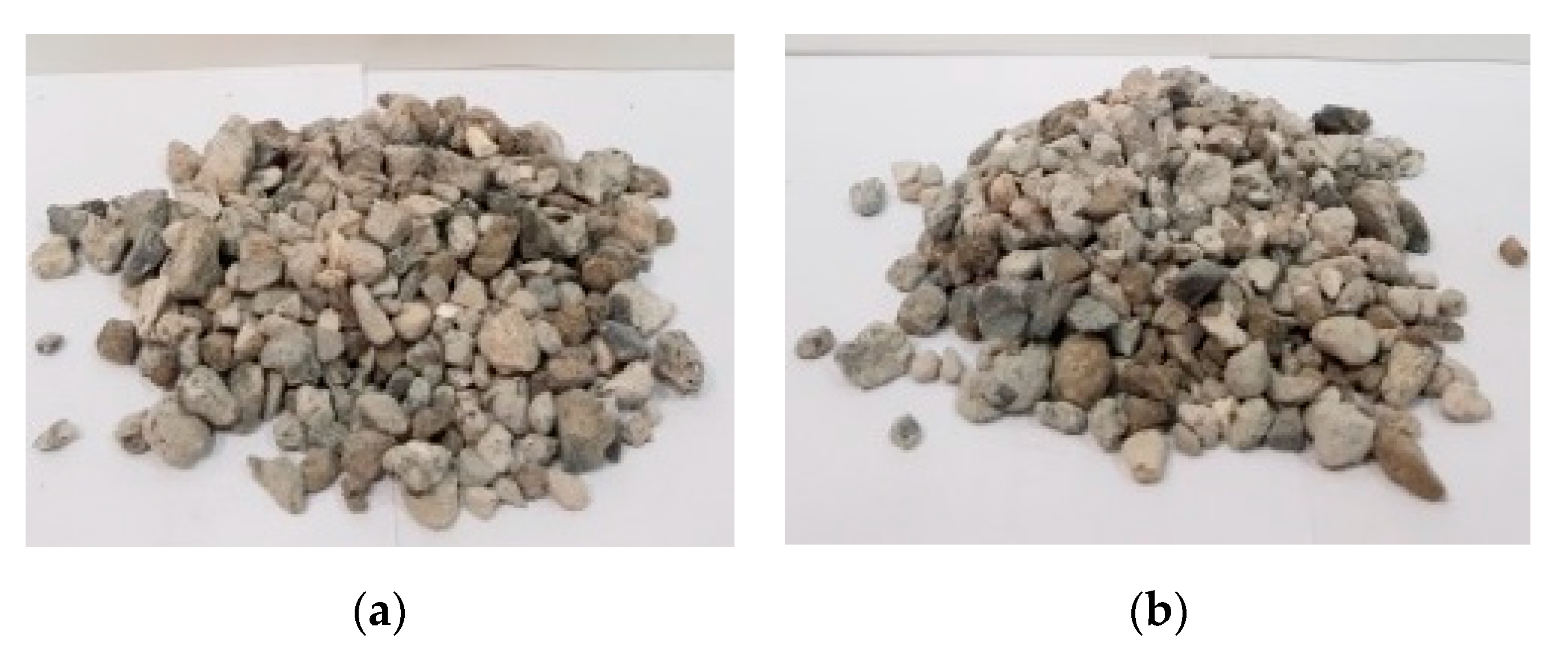
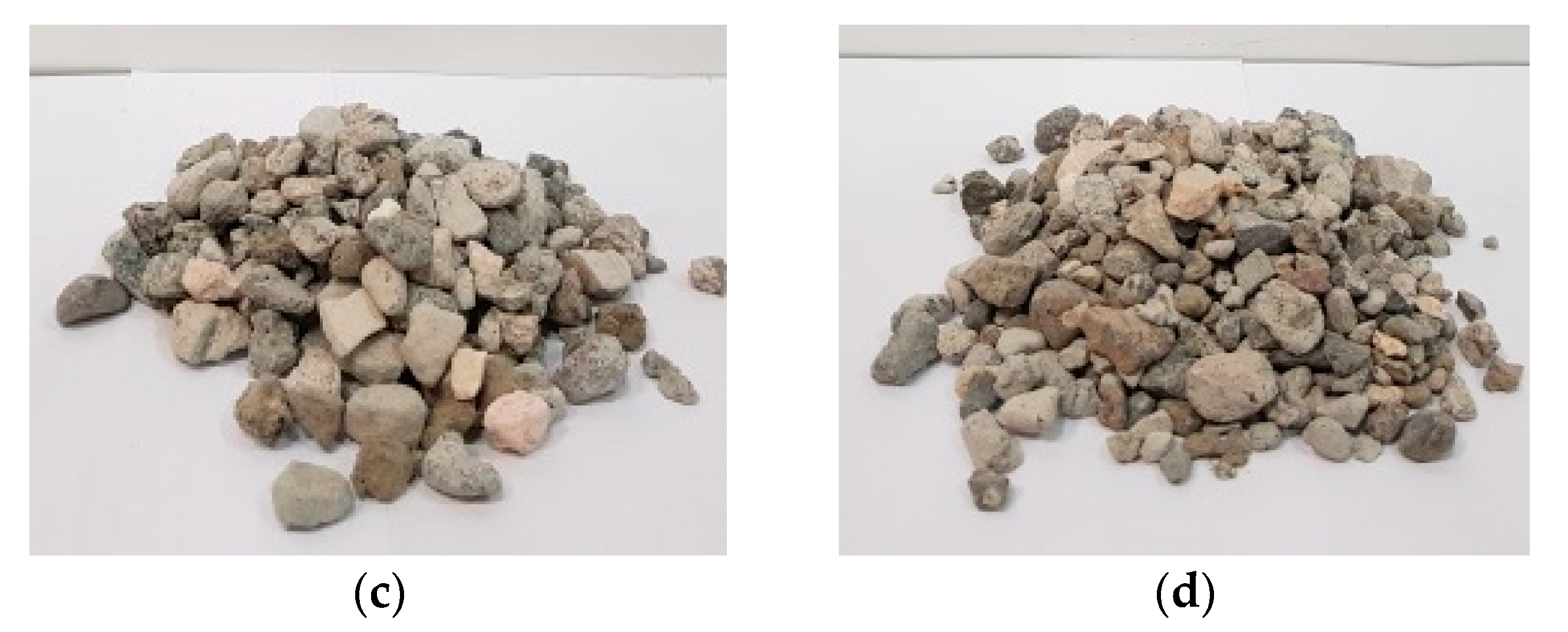
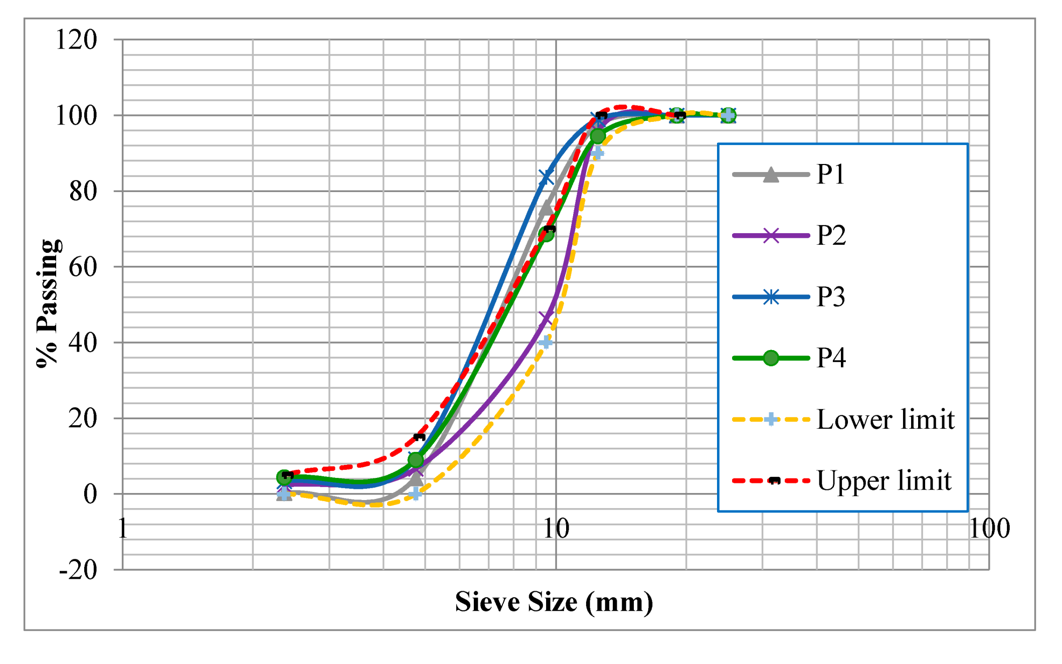
2.1.1. Recycled Aggregate
2.1.2. Fibers
2.1.3. Other Materials
2.2. Mix Proportioning and Mixing Procedure
2.3. Testing Program
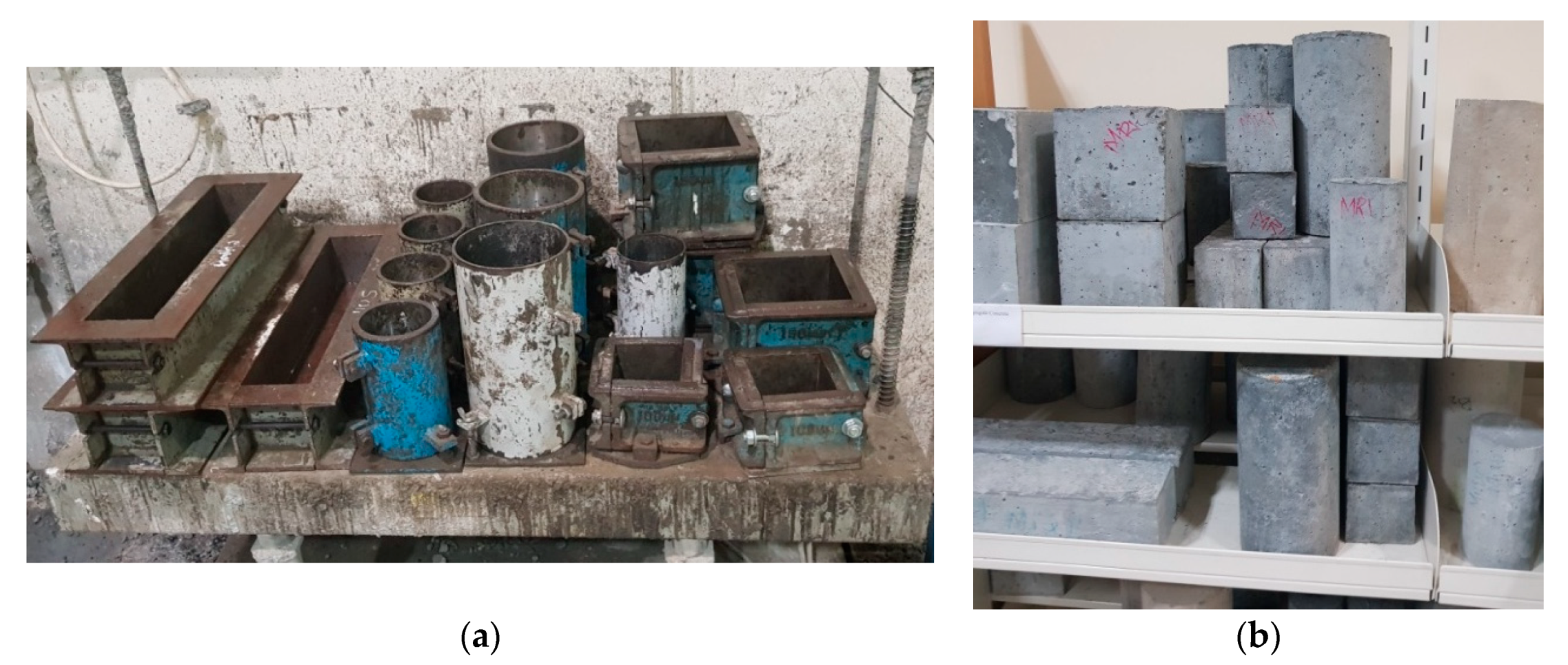
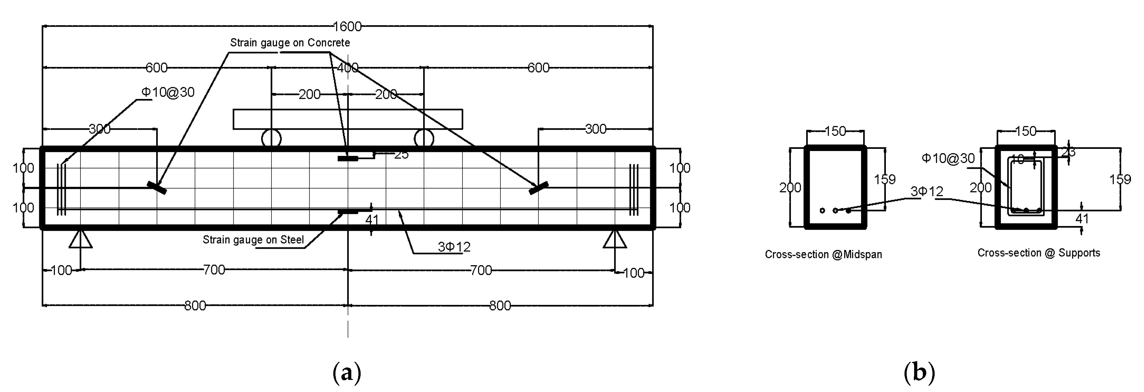
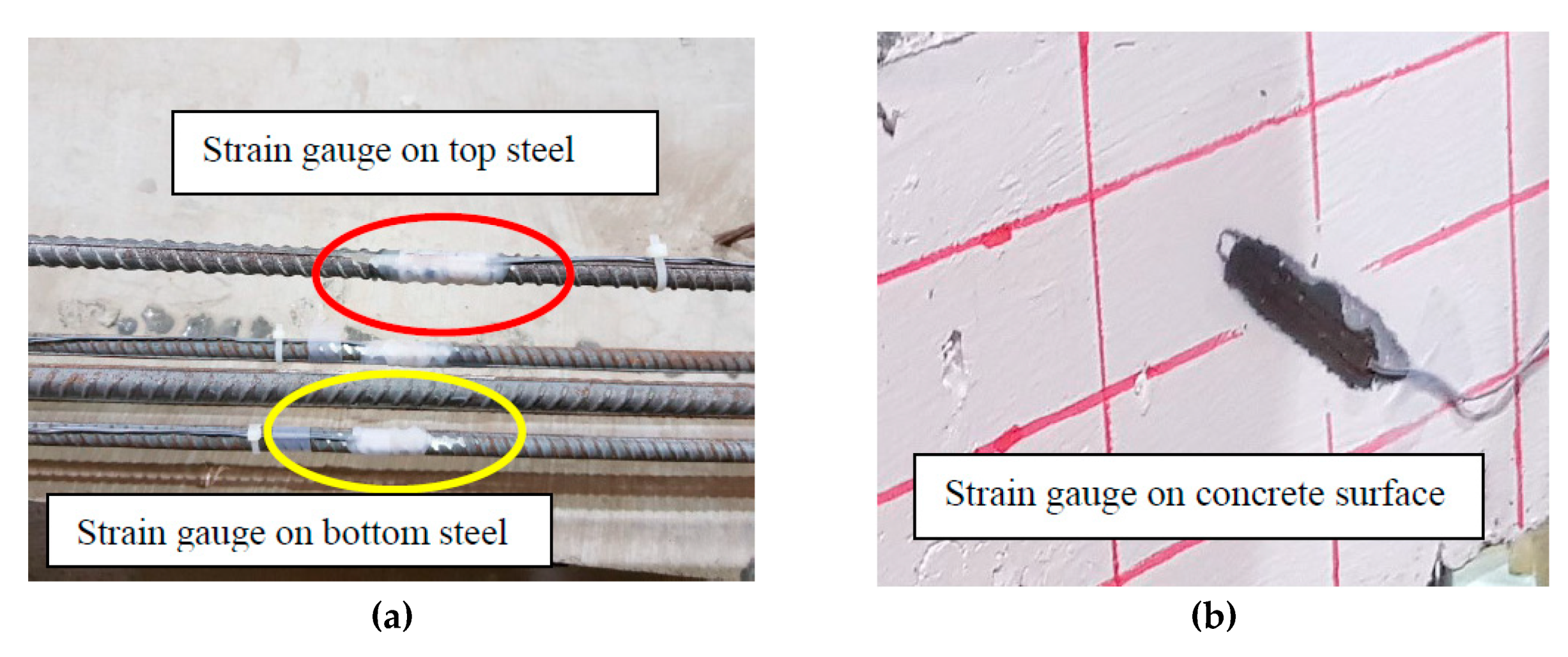
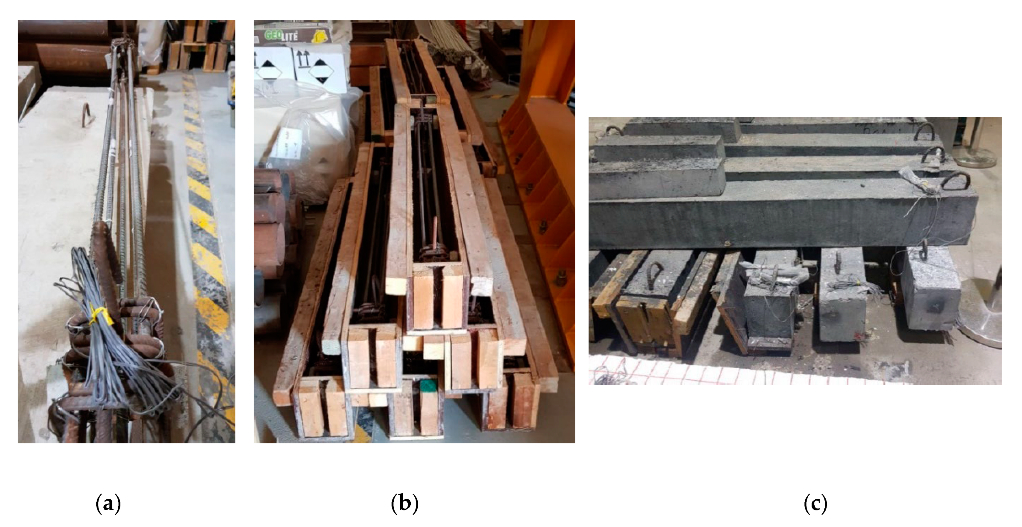
2.3.1. Sample Preparation
2.3.2. Test Setup
3. Results
3.1. Evaluation of Mechanical Properties
3.1.1. Compressive Strength and Splitting Tensile Strength
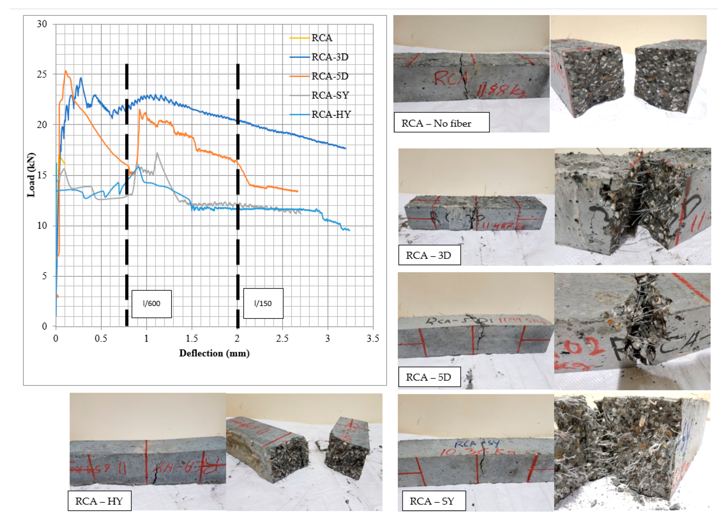
3.1.2. Flexural Strength
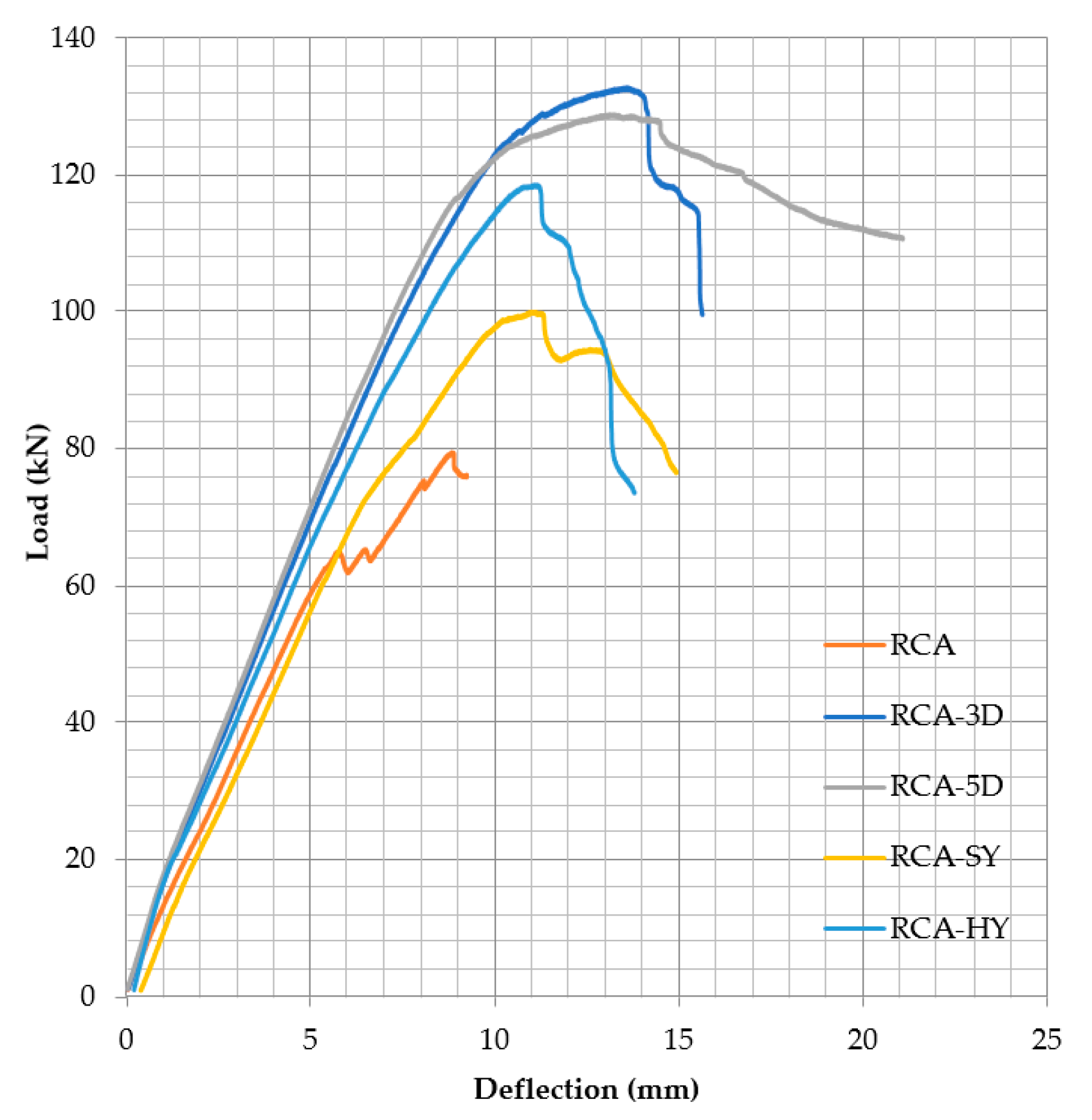
3.2. Concrete Contribution to Shear Resistance
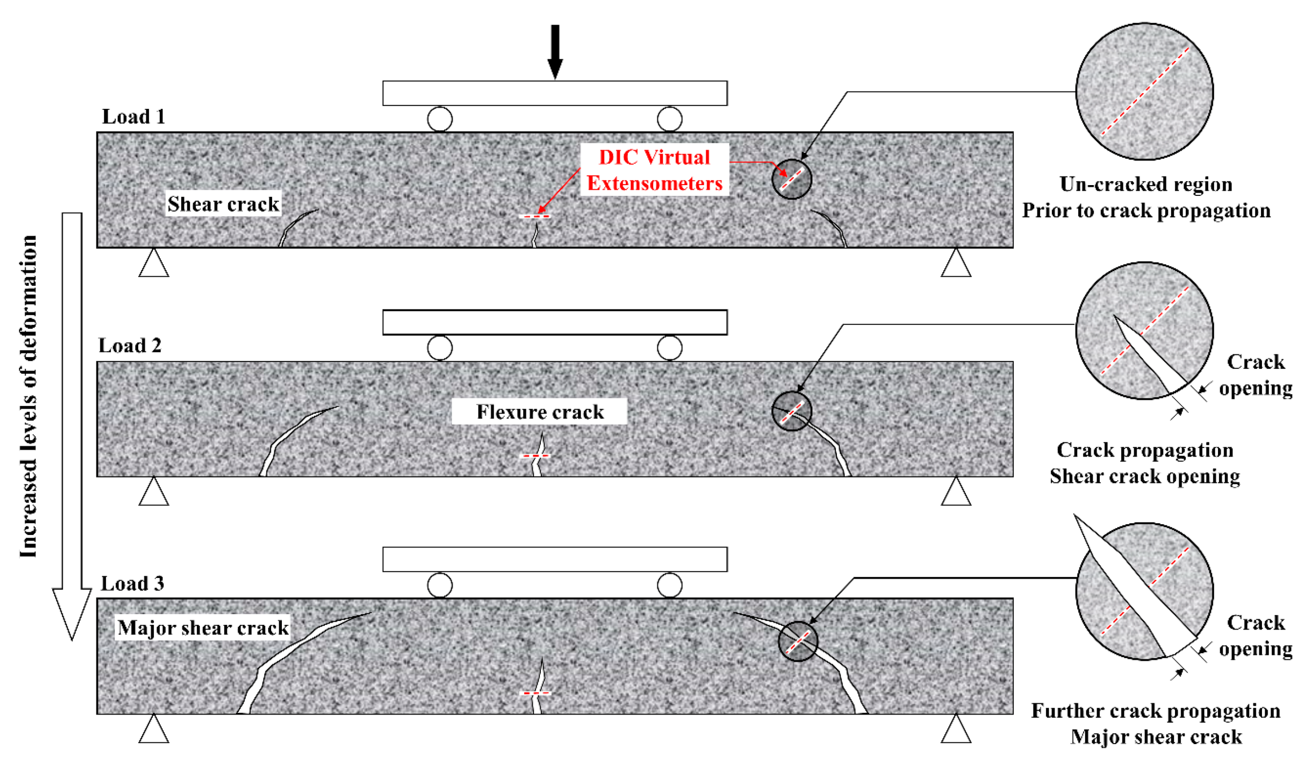
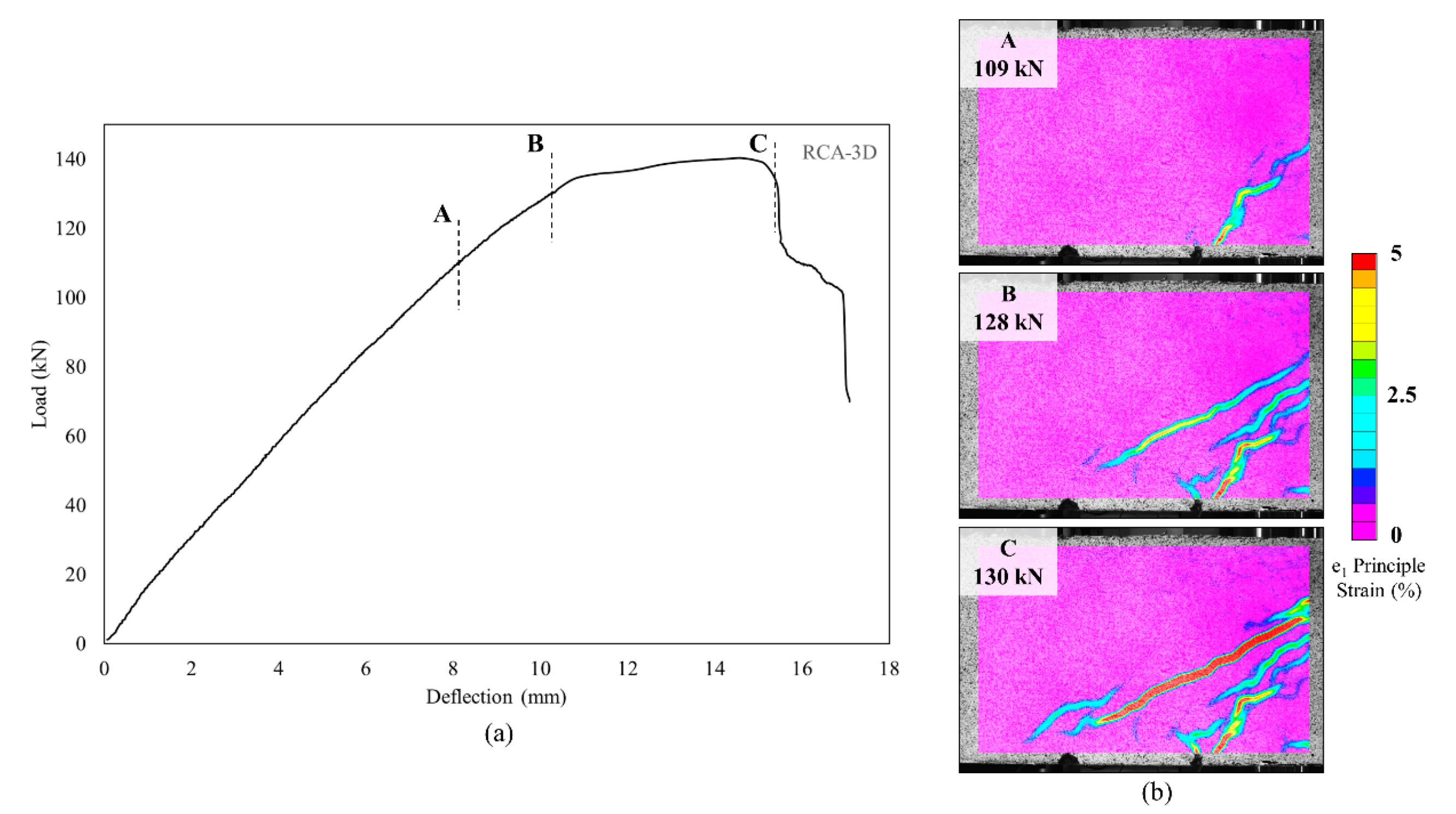
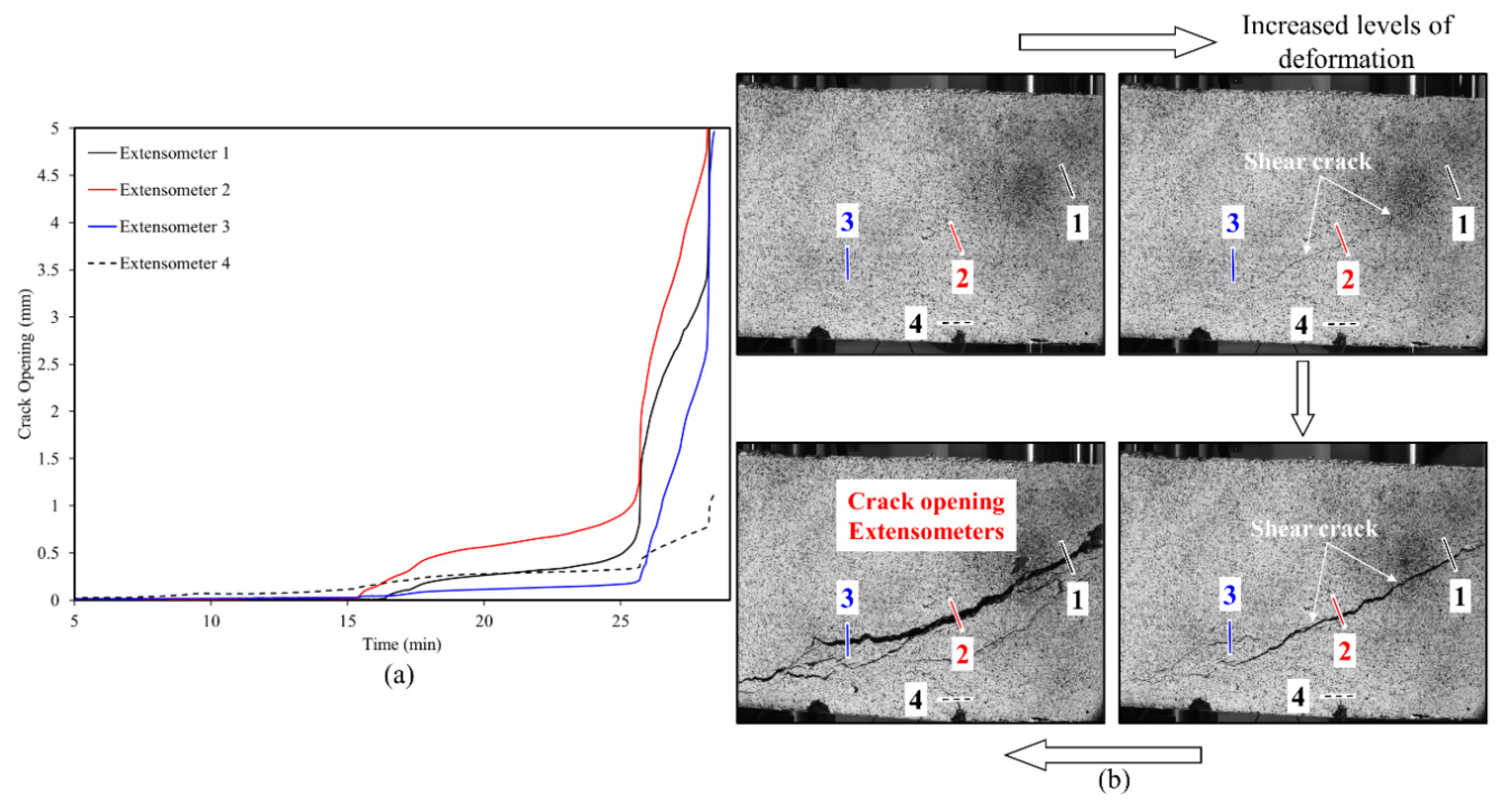
3.3. Full-Field Deformation Measurments—Crack Opening
4. Discussion
4.1. Effect of Fiber Addition on the Mechanical Properties
Effect of Fiber Type on the Mechanical Properties
4.2. Comparison of Mechanical Properties with Results from Literature
4.3. Effect of Fiber Addition on Shear Performance
4.3.1. Effect of Fiber on Concrete Shear Capacity
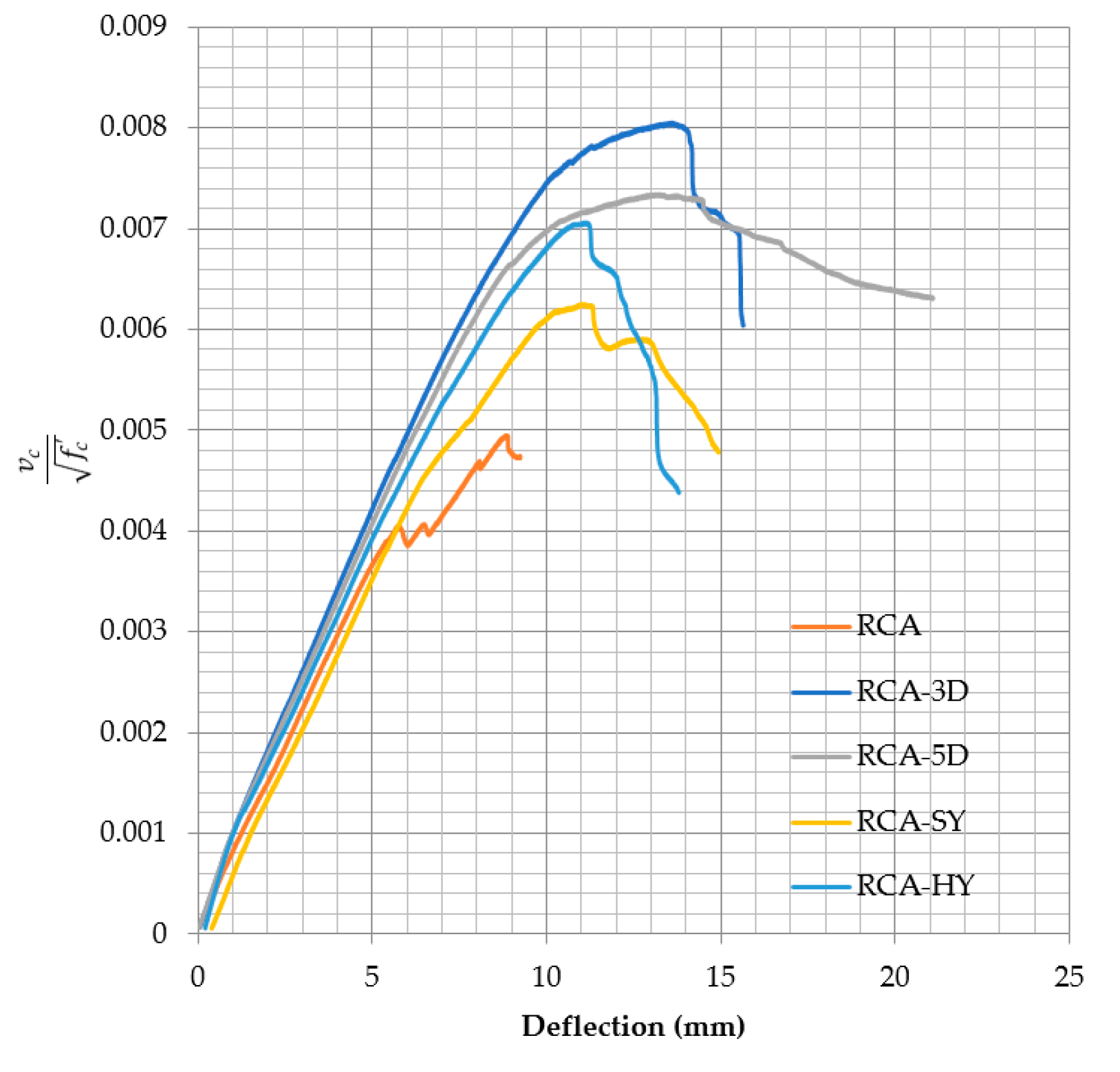
4.3.2. Effect Fiber on Stiffness
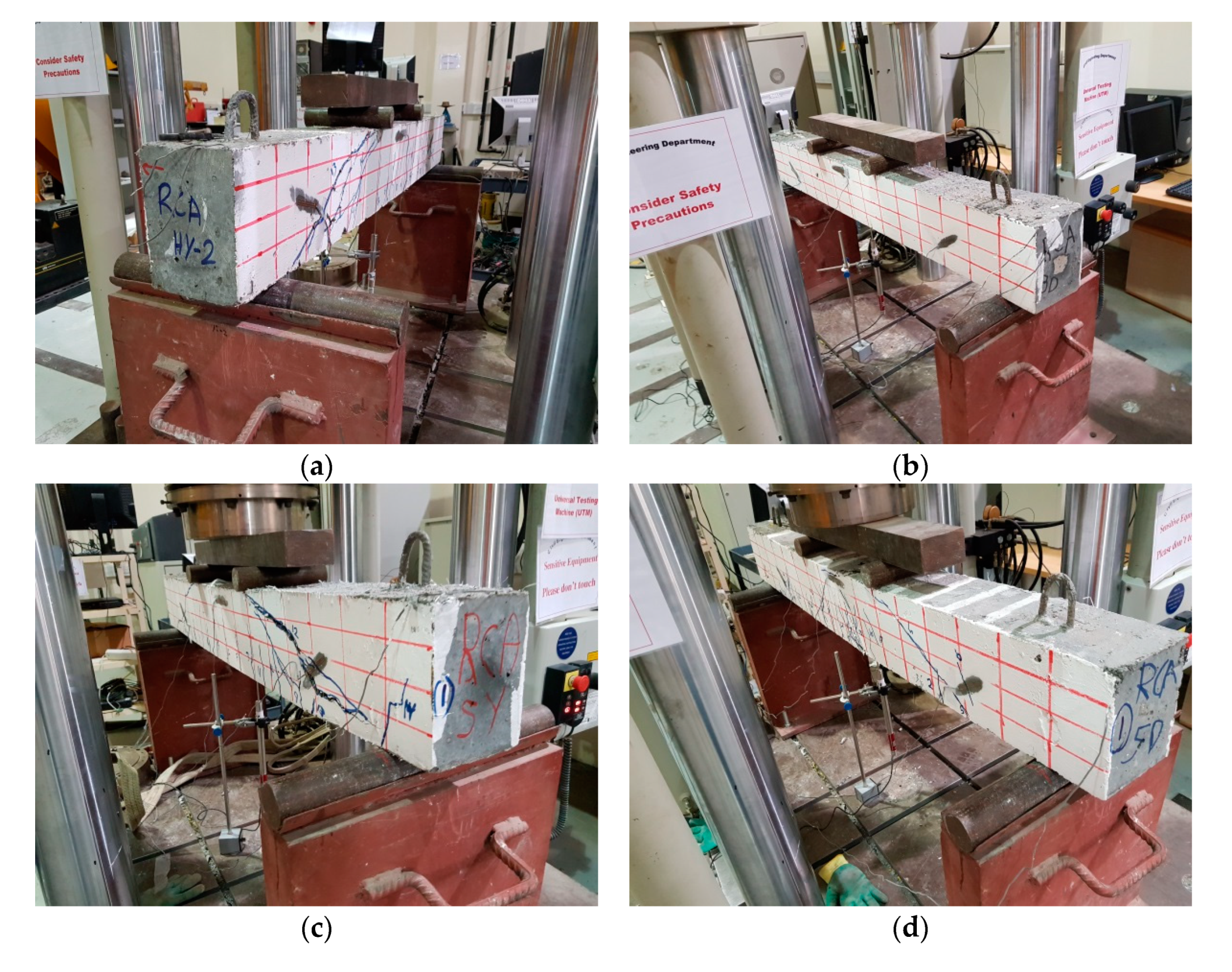
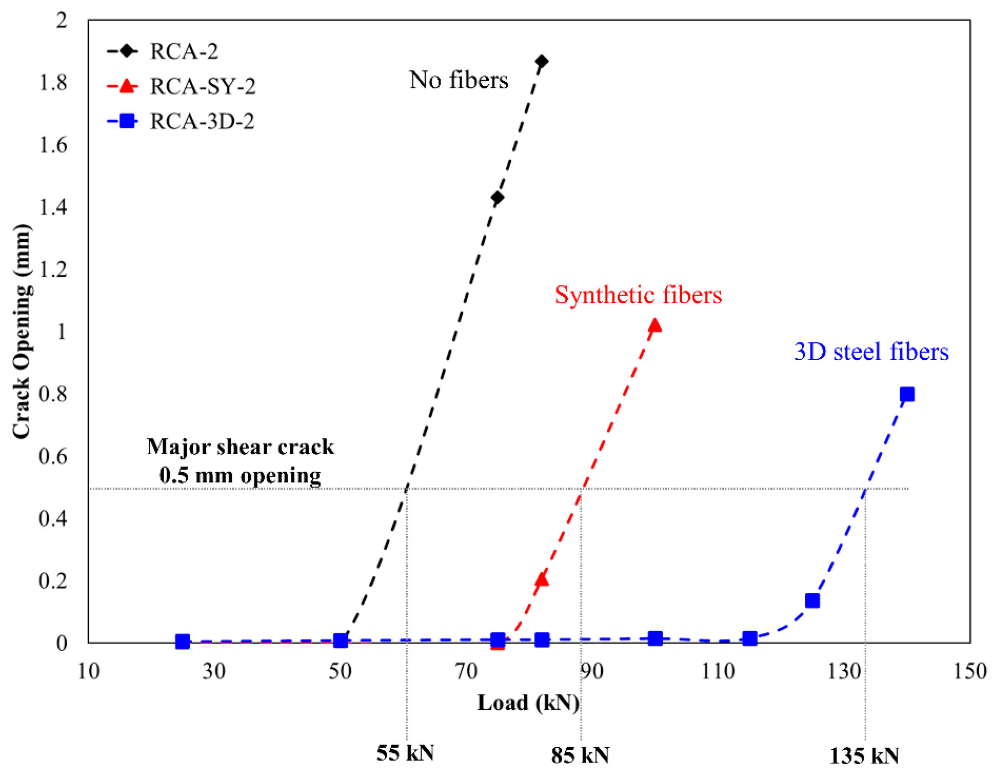
4.3.3. Effect of Fiber on Crack Initiation, Crack Pattern, and Failure Modes
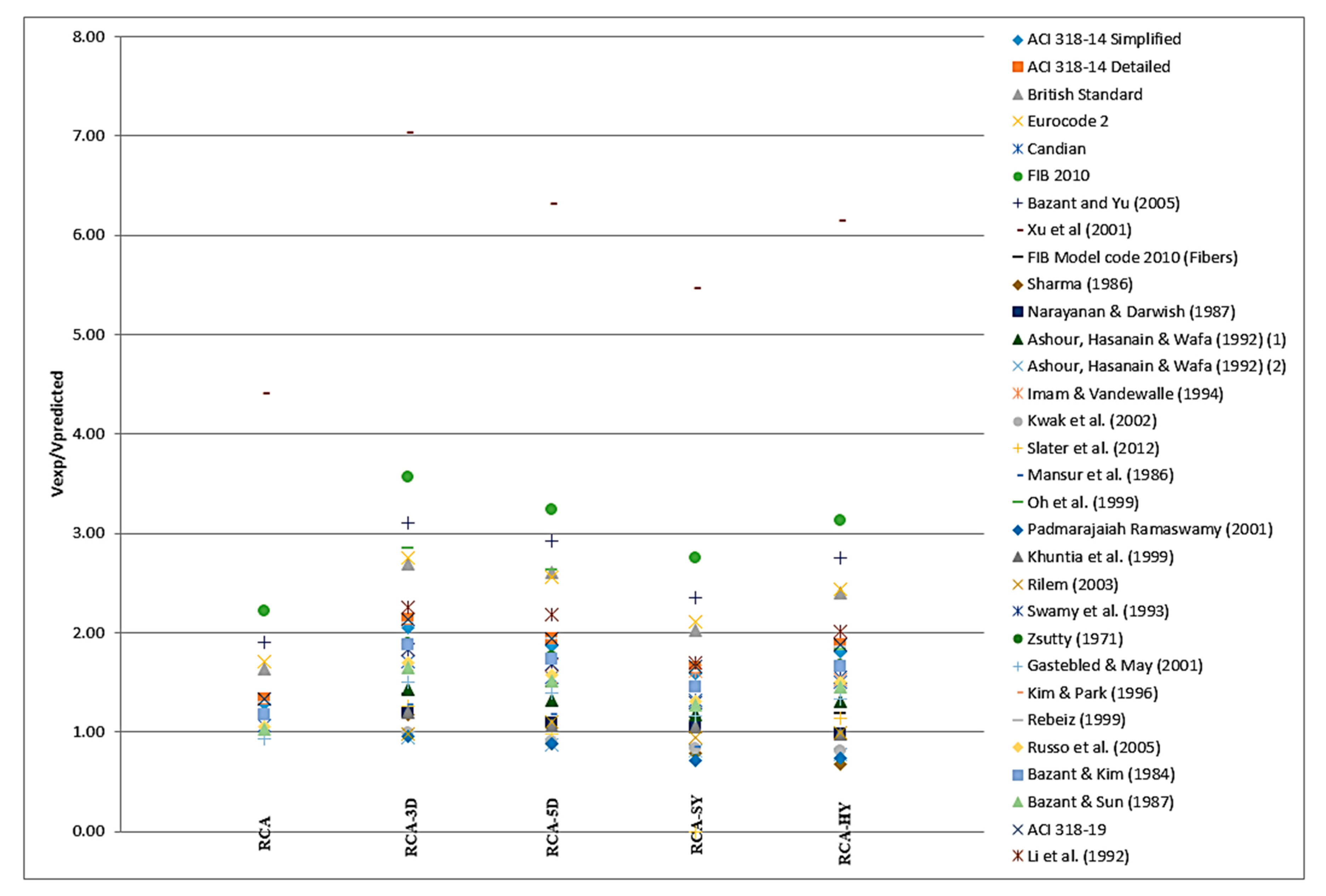
4.4. Summary of Fiber-Reinforced Experimental Results Versus Proposed Equations
4.4.1. Applicability of NW Models Tested on Previous RAC Studies
4.4.2. Applicability of NW Models on Current RAC Study
4.4.3. Applicability of Fiber Reinforced Concrete with NW Models on Fiber RAC
4.4.4. Applicability of Code Equations on RAC and Fiber RAC
4.4.5. Specific Cases
5. Conclusions
- Performance of concrete mixes with 100% recycled coarse aggregate is improved by adopting an enhanced mixing procedure and the addition of silica fume. Both helped increase the compressive strength, the cement paste-aggregate bond, enhanced the microstructure and improved the ITZ.
- The fiber addition improved the crack initiation, propagation and post cracking behavior, which led to ductile behavior and different mode of failures. All fiber types improved the splitting (72 to 140%, 3D, SY, 5D, and HY) and the flexural strengths (8 to 72%, HY, SY, 3D, and 5D); however, the percentage improvement was influenced by the fiber type and configuration. It is important to note that not all fiber types improved the compressive strength.
- Concrete contribution to shear capacity of the control beams could be predicated by the current codes and shear failure is similar to that of found in the literature for beams without shear reinforcement.
- The fiber addition led to delay of the first crack, controlled crack width and crack propagation. The first shear crack of all fiber reinforced specimens was initiated when the longitudinal reinforcement reached or closer to yield. All fiber types improved the concrete contribution to the shear capacity. Steel fibers 3D and 5D showed the best performance and increase in shear capacity. The percentage increase was 64.48%, 59.23%, 47%, and 23.4% for the 3D, 5D, HY, and SY, respectively, compared to the control specimens.
- The improved configuration of the 5D steel fibers increased the anchorage with surrounding concrete, which enhanced the flexural strength and contributed to improving the concrete shear resistance.
- Synthetic fibers, in this study, showed limited contribution, which could be attributed to low fiber stiffness, lack of anchorage and less pullout capacity compared to the steel fibers. On the other hand, the hybrid mix, RCA-HY, showed relatively mixed results due to the combination of 50% of synthetic fibers and 50% of 5D steel fibers.
- For RAC, the Canadian and ACI 318 codes could be used to calculate the concrete shear capacity with an acceptable factor of safety.
- For fiber RAC, the fib Model Code 2010 (with fibers) provides an acceptable model to calculate the concrete shear capacity for fiber reinforced concrete.
- Direct observation of cracking response using DIC, initiation and propagation, enables quantitative assessment of role of fiber addition. The introduction of synthetic fibers delayed shear crack initiation compared to RCA beams with no fiber reinforcement. 3D steel fibers offered additional improvement. In both cases, smaller crack widths were confirmed for fiber reinforced beams compared to RCA at similar loads.
- Long-term monitoring and evaluation of fiber reinforced recycled aggregate concrete is recommended to validate the finding of the current study.
Author Contributions
Funding
Acknowledgments
Conflicts of Interest
Disclaimer
References
- Tam, V.W.Y.; Soomro, M.; Evangelista, A. A Review of Recycled Aggregate in Concrete Applications (2000–2017). Constr. Build. Mater. 2018, 172, 272–292. [Google Scholar] [CrossRef]
- Le, H.; Bui, Q. Recycled aggregate concretes—A state-of-the-art from the Microstructure to the Structural Performance. Constr. Build. Mater. 2020, 257, 119522. [Google Scholar] [CrossRef]
- Silva, R.V.; de Brito, J.; Dhir, R.K. Fresh-state Performance of Recycled Aggregate Concrete: A Review. Constr. Build. Mater. 2018, 178, 19–31. [Google Scholar] [CrossRef]
- Martínez-Lage, I.; Vázquez-Burgo, P.; Velay-Lizancos, M. Sustainability Evaluation of Concretes with Mixed Recycled Aggregate Based on Holistic Approach: Technical, Economic and Environmental analysis. Waste Manag. 2020, 104, 9–19. [Google Scholar] [CrossRef] [PubMed]
- Visintin, P.; Xie, T.; Bennett, B. A Large-scale Life-cycle Assessment of Recycled Aggregate Concrete: The Influence of Functional Unit, Emissions Allocation and Carbon Dioxide Uptake. J. Clean. Prod. 2020, 248, 119243. [Google Scholar] [CrossRef]
- Hatungimana, D.; Yazıcı, Ş.; Mardani-Aghabaglou, A. Effect of Recycled Concrete Aggregate Quality on Properties of Concrete. J. Green Build. 2020, 15, 57–69. [Google Scholar] [CrossRef]
- Abdelfatah, A.; Tabsh, S.; Yehia, S. Utilization of Recycled Coarse Aggregate in Concrete Mixes. J. Civ. Eng. Archit. 2011, 5, 562–566. [Google Scholar] [CrossRef] [Green Version]
- Medina, C.; Zhu, W.; Howind, T.; Sánchez de Rojas, M.; Frías, M. Influence of Mixed Recycled Aggregate on the Physical—Mechanical Properties of Recycled Concrete. J. Clean. Prod. 2014, 68, 216–225. [Google Scholar] [CrossRef]
- Yehia, S.; Helal, K.; Abu-Sharhk, A.; Zaher, A.; Istaytehl, H. Strength and Durability Evaluation of Recycled Aggregate Concrete. Int. J. Concr. Struct. Mater. 2015, 9, 219–239. [Google Scholar] [CrossRef] [Green Version]
- Yehia, S.; Farrag, S.; Abu-Sharhk, A.; Zaher, A.; Istaytehl, H.; Helal, K. Concrete with Recycled Aggregate: Evaluation of Mechanical Properties. GSTF J. Eng. Technol. (JET) 2015, 3, 37–44. [Google Scholar]
- Yehia, S.; Abdelfatah, A. Examining the Variability of Recycled Concrete Aggregate Properties. In Proceedings of the International Conference on Civil, Architecture and Sustainable Development (CASD-2016), London, UK, 1–2 December 2016. [Google Scholar]
- Tayeh, B.A.; Al Saffar, D.M.; Alyousef, R. The Utilization of Recycled Aggregate in High Performance Concrete: A Review. J. Mater. Res. Technol. 2020, 9, 8469–8481. [Google Scholar] [CrossRef]
- Cantero, B.; Bravo, M.; de Brito, J.; Sáez del Bosque, I.F.; Medina, C. Mechanical Behavior of Structural Concrete with Ground Recycled Concrete Cement and Mixed Recycled Aggregate. J. Clean. Prod. 2020, 275, 122913. [Google Scholar] [CrossRef]
- Yehia, S.; Abdelfatah, A.; Mansour, D. Effect of Aggregate Type and Specimen Configuration on Concrete Compressive Strength. Crystals 2020, 10, 625. [Google Scholar] [CrossRef]
- Arezoumandi, M.; Drury, J.; Volz, J.S.; Khayat, K.H. Effect of Recycled Concrete Aggregate Replacement Level on Shear Strength of Reinforced Concrete Beams. ACI Mater. J. 2015, 112, 559. [Google Scholar] [CrossRef]
- Arezoumandi, M.; Smith, A.; Volz, J.S.; Khayat, K.H. An Experimental Study on Flexural Strength of Reinforced Concrete Beams with 100% Recycled Concrete Aggregate. Eng. Struct. 2015, 88, 154–162. [Google Scholar] [CrossRef]
- Rahal, K.N.; Al-Khaleefi, A.-L. Shear-Friction Behavior of Recycled and Natural Aggregate Concrete—An Experimental Investigation. ACI Struct. J. 2015, 112, 725–734. [Google Scholar] [CrossRef]
- Kikuchi, M.; Mukai, T.; Koizumi, H. Properties of Concrete Products Containing Recycled Aggregate. In Proceedings of the Second International Symposium on Demolition and Reuse of Concrete and Masonry, Tokyo, Japan, 7–11 November 1988; Volume 2, pp. 595–604. [Google Scholar]
- Maruyama, S.M.; Sogabe, T.; Sato, R.; Kawai, K. Flexural Properties of Reinforced Recycled Concrete Beams. In Proceedings of the International RILEM Conference on the Use of Recycled Materials in Buildings and Structures, Barcelona, Spain, 8–11 November 2004; p. 315. [Google Scholar]
- González-Fonteboa, B.; Martinez-Abella, F. Shear Strength of Recycled Concrete Beams. Constr. Build. Mater. 2007, 21, 887–893. [Google Scholar] [CrossRef]
- González-Fonteboa, B.; Martinez-Abella, F.; Martínez-Lage, I.; Eiras-López, J. Structural Shear Behavior of Recycled Concrete with Silica Fume. Constr. Build. Mater. 2009, 23, 3406–3410. [Google Scholar] [CrossRef]
- Choi, H.; Yi, C.; Cho, H.; Kang, K. Experimental Study on the Shear Strength of Recycled Aggregate Concrete Beams. Mag. Concr. Res. 2010, 62, 103–114. [Google Scholar] [CrossRef]
- Fathifazl, G.; Razaqpur, A.G.; Isgor, B.O.; Abbas, A.; Fournier, B.; Foo, S. Flexural Performance of Steel-Reinforced Recycled Concrete Beams. ACI Struct. J. 2009, 106, 858–867. [Google Scholar]
- Tabsh, S.; Yehia, S. Shear Strength of Reinforced Concrete Beams Made with Recycled Aggregate. In Proceedings of the 3rd CSEE Congress, Budapest, Hungary, 8–10 April 2018; CSEE: Budapest, Hungary, 2018. [Google Scholar]
- Meddah, M.S.; Bencheikh, M. Properties of Concrete Reinforced with Different Kinds of Industrial Waste Fibre Materials. Constr. Build. Mater. 2009, 23, 3196–3205. [Google Scholar] [CrossRef]
- Carneiro, J.A.; Lima, P.R.L.; Leite, M.B.; Filho, R.D.T. Compressive Stress–Strain Behavior of Steel Fiber Reinforced-Recycled Aggregate Concrete. Cem. Concr. Compos. 2014, 46, 65–72. [Google Scholar] [CrossRef]
- Chen, G.; He, Y.; Yang, H.; Chen, J.; Guo, Y. Compressive Behavior of Steel Fiber Reinforced Recycled Aggregate Concrete After Exposure to Elevated Temperatures. Constr. Build. Mater. 2014, 71, 1–15. [Google Scholar] [CrossRef] [Green Version]
- Mohseni, E.; Saadati, R.; Kordbacheh, N.; Parpinchi, Z.S.; Tang, W. Engineering and Microstructural Assessment of Fibre-Reinforced Self-Compacting Concrete Containing Recycled. J. Clean. Prod. 2017, 168, 605–613. [Google Scholar] [CrossRef]
- Afroughsabet, V.; Biolzi, L.; Ozbakkaloglu, T. Influence of Double Hooked-end Steel Fibers and Slag on Mechanical and Durability Properties of High Performance Recycled Aggregate Concrete. Compos. Struct. 2017, 181, 273–284. [Google Scholar] [CrossRef]
- Gao, D.; Zhang, L. Flexural Performance and Evaluation Method of Steel Fiber Reinforced Recycled Coarse Aggregate Concrete. Constr. Build. Mater. 2018, 159, 126–136. [Google Scholar] [CrossRef]
- Altun, M.G.; Oltulu, M. Effect of Different Types of Fiber Utilization on Mechanical Properties of Recycled Aggregate Concrete Containing Silica Fume. J. Green Build. 2020, 15, 119–136. [Google Scholar] [CrossRef]
- Ahmed, T.W.; Ali, A.A.M.; Zidan, R.S. Properties of High Strength Polypropylene Fiber Concrete Containing Recycled Aggregate. Constr. Build. Mater. 2020, 241, 118010. [Google Scholar] [CrossRef]
- Matar, P.; Zéhil, G. Effects of Polypropylene Fibers on the Physical and Mechanical Properties of Recycled Aggregate Concrete. J. Wuhan Univ. Technol. Sci. Ed. 2019. [Google Scholar] [CrossRef]
- Gao, D.; Zhang, L.; Nokken, M. Compressive Behavior of Steel Fiber Reinforced Recycled Coarse Aggregate Concrete Designed With Equivalent Cubic Compressive Strength. Constr. Build. Mater. 2017, 141, 235–244. [Google Scholar] [CrossRef] [Green Version]
- ACI318–19. Building Code Requirements for Structural Concrete; American Concrete Institute: Farmington Hills, MI, USA, 2019. [Google Scholar]
- Schubert, S.; Hoffmann, C.; Leemann, A.; Moser, K.; Motavalli, M. Recycled Aggregate Concrete: Experimental Shear Resistance of Slabs without Shear Reinforcement. Eng. Struct. 2012, 41, 490–497. [Google Scholar] [CrossRef]
- Schaul, P.; Balázs, G. Shear Design Formulas for FRP and Synthetic Fiber Reinforced Concrete Beams. Concr. Struct. 2017, 18, 16–20. [Google Scholar]
- Alhassan, M.; Al-Rousan, R.; Ababneh, A. Flexural Behavior of Lightweight Concrete Beams Encompassing Various Dosages of Macro Synthetic Fibers and Steel Ratios. Case Stud. Constr. Mater. 2017, 7, 280–293. [Google Scholar] [CrossRef]
- Akça, K.R.; Çakır, Ö.; Ipek, M. Properties of Polypropylene Fiber Reinforced Concrete using Recycled Aggregates. Constr. Build. Mater. 2015, 98, 620–630. [Google Scholar] [CrossRef]
- Ahmadi, M.; Farzin, S.; Hassani, A.; Motamedi, M. Mechanical Properties of The Concrete Containing Recycled Fibers and Aggregates. Constr. Build. Mater. 2017, 144, 392–398. [Google Scholar] [CrossRef]
- Fib Model Code for Concrete Structures 2010; Ernst & Sohn Publishing House: Berlin, Germany, 2013. [CrossRef]
- Canadian Standard Association. Design of Concrete Structures; CSA Standard A23 3-04; CSA: Rexdale, ON, Canada, 2000. [Google Scholar]
- E. C. for Standardization, EN 1992-1-1 Eurocode 2: Design of Concrete Structures—Part 1-1: General Rules and Rules for Buildings; CEN: Brussels, Belgium, 2005.
- BS 8110 Structural Use of Concrete—Part 1: Code of Practice for Design and Construction; British Standards Institution: London, UK, 1997.
- ACI 318-14: Building Code Requirements for Structural Concrete: Commentary on Building Code Requirements for Structural Concrete (ACI 318R-19); American Concrete Institute: Farmington Hills, MI, USA, 2014.
- RILEM TC 162-TDF. Final Recommendation of: Test and Design Methods for Steel Fiber Reinforced Concrete Sigma-Epsilon-Design Method. Mater. Struct. 2003, 36, 560–567. [Google Scholar] [CrossRef]
- Fathifazl, G.; Razaqpur, A.G.; Isgor, O.B.; Abbas, A.; Fournier, B.; Foo, S. Shear Strength of Reinforced Recycled Concrete Beams without Stirrups. Mag. Concr. Res. 2009, 61, 477–490. [Google Scholar] [CrossRef]
- Fathifazl, G.; Razaqpur, A.G.; Isgor, O.B.; Abbas, A.; Fournier, B.; Foo, S. Shear Capacity Evaluation of Steel Reinforced Recycled Concrete (RRC) Beams. Eng. Struct. 2011, 33, 1025–1033. [Google Scholar] [CrossRef]
- Yun, H.D.; You, Y.C.; Lee, D.H. Effects of Replacement Ratio of Recycled Coarse Aggregate on The Shear Performance of Reinforced Concrete Beams without Shear Reinforcement. LHI J. Land Hous. Urban Aff. 2011, 2, 471–477. [Google Scholar] [CrossRef] [Green Version]
- Ceia, F.; Raposo, J.; Guerra, M.; Júlio, E.; De Brito, J. Shear Strength of Recycled Aggregate Concrete to Natural Aggregate Concrete Interfaces. Constr. Build. Mater. 2016, 109, 139–145. [Google Scholar] [CrossRef]
- Katkhuda, H.; Shatarat, N. Shear Behavior of Reinforced Concrete Beams using Treated Recycled Concrete Aggregate. Constr. Build. Mater. 2016, 125, 63–71. [Google Scholar] [CrossRef]
- Sadati, S.; Arezoumandi, M.; Khayat, K.H.; Volz, J.S. Shear Performance of Reinforced Concrete Beams Incorporating Recycled Concrete Aggregate and High-Volume Fly Ash. J. Clean. Prod. 2016, 115, 284–293. [Google Scholar] [CrossRef]
- Waseem, S.A.; Singh, B. Shear Transfer Strength of Normal and High-Strength Recycled Aggregate Concrete—An Experimental Investigation. Constr. Build. Mater. 2016, 125, 29–40. [Google Scholar] [CrossRef]
- Ignjatović, I.S.; Marinković, S.B.; Tošić, N. Shear Behavior of Recycled Aggregate Concrete Beams with and without Shear Reinforcement. Eng. Struct. 2017, 141, 386–401. [Google Scholar] [CrossRef]
- Rahal, K. Shear strength of recycled aggregates concrete. Procedia Eng. 2017, 210, 105–108. [Google Scholar] [CrossRef]
- Rahal, K.N.; Alrefaei, Y.T. Shear Strength of Longitudinally Reinforced Recycled Aggregate Concrete Beams. Eng. Struct. 2017, 145, 273–282. [Google Scholar] [CrossRef]
- Pradhan, S.; Kumar, S.; Barai, S.V. Shear Performance of Recycled Aggregate Concrete Beams: An Insight for Design Aspects. Constr. Build. Mater. 2018, 178, 593–611. [Google Scholar] [CrossRef]
- Wardeh, G.; Ghorbel, E.; Gomart, H.; Fiorio, B.; Pliya, P. Shear Behavior of Reinforced Recycled Aggregate Concrete Beams. In High Tech Concrete: Where Technology and Engineering Meet; Springer: Cham, Switzerland, 2018; pp. 508–515. [Google Scholar]
- Al-Jasimee, D.H.; Dhaheer, M.A. Shear Behavior of Reinforced Self-Compacting Concrete Beams Made with Treated Recycled Aggregate. Al-Qadisiyah J. Eng. Sci. 2019, 12, 193–198. [Google Scholar]
- Mohammed, T.U.; Shikdar, K.H.; Awal, M.A. Shear Strength of RC Beam Made with Recycled Brick Aggregate. Eng. Struct. 2019, 189, 497–508. [Google Scholar] [CrossRef]
- Wardeh, G.; Ghorbel, E. Shear Strength of Reinforced Concrete Beams with Recycled Aggregates. Adv. Struct. Eng. 2019, 22, 1938–1951. [Google Scholar] [CrossRef]
- Li, C.; Liang, N.; Zhao, M.; Yao, K.; Li, J.; Li, X. Shear Performance of Reinforced Concrete Beams Affected by Satisfactory Composite-Recycled Aggregates. Materials 2020, 13, 1711. [Google Scholar] [CrossRef] [PubMed] [Green Version]
- Al Mahmoud, F.; Boissiere, R.; Mercier, C.; Khelil, A. Shear Behavior of Reinforced Concrete Beams Made from Recycled Coarse and Fine Aggregates. Structures 2020, 25, 660–669. [Google Scholar] [CrossRef]
- Etman, E.E.; Afefy, H.M.; Baraghith, A.T.; Khedr, S.A. Improving the Shear Performance of Reinforced Concrete Beams Made of Recycled Coarse Aggregate. Constr. Build. Mater. 2018, 185, 310–324. [Google Scholar] [CrossRef]
- Chaboki, H.R.; Ghalehnovi, M.; Karimipour, A.; Brito, J.D.; Khatibinia, M. Shear Behavior of Concrete Beams with Recycled Aggregate and Steel Fibres. Constr. Build. Mater. 2019, 204, 809–827. [Google Scholar] [CrossRef]
- Sayhood, E.K.; Resheq, A.S.; Raoof, F.L. Behavior of Recycled Aggregate Fibrous Reinforced Beams Under Flexural and Shear Loading. Eng. Technol. J. 2019, 37, 338–344. [Google Scholar]
- Wang, Y.; Hughes, P.; Niu, H.; Fan, Y. A New Method to Improve the Properties of Recycled Aggregate Concrete: Composite Addition of Basalt Fiber and Nano-Silica. J. Clean. Prod. 2019, 236, 117602. [Google Scholar] [CrossRef]
- Yehia, S.; Alhamaydeh, M.; Farrag, S. High-Strength Lightweight SCC Matrix with Partial Normal-Weight Coarse-Aggregate Replacement: Strength and Durability Evaluations. J. Mater. Civ. Eng. 2014, 26, 04014086. [Google Scholar] [CrossRef]
- Narayanan, R.; Darwish, I.Y.S. Use of Steel Fibers as Shear Reinforcement. Struct. J. 1987, 84, 216–227. [Google Scholar]
- Adebar, P.; Mindess, S.; Pierre, D.S.; Olund, B. Shear Tests of Fiber Concrete Beams without Stirrups. Struct. J. 1997, 94, 68–76. [Google Scholar]
- Khuntia, M.; Stojadinovic, B.; Goel, S.C. Shear Strength of Normal and High-Strength Fiber Reinforced Concrete Beams without Stirrups. Struct. J. 1999, 96, 282–289. [Google Scholar]
- Dinh, H.H.; Parra-Montesinos, G.J.; Wight, J.K. Shear Behavior of Steel Fiber-Reinforced Concrete Beams without Stirrup Reinforcement. ACI Struct. J. 2010, 107, 1039–1051. [Google Scholar]
- Dinh, H.H.; Parra-Montesinos, G.J.; Wight, J.K. Shear Strength Model for Steel Fiber Reinforced Concrete Beams without Stirrup Reinforcement. J. Struct. Eng. 2011, 137, 1039–1051. [Google Scholar] [CrossRef]
- ASTM C642-13 Standard Test Method for Density, Absorption, and Voids in Hardened Concrete; ASTM International: West Conshohocken, PA, USA, 2013.
- ASTM C127–15. Standard Test Method for Relative Density (Specific Gravity) and Absorption of Coarse Aggregate; ASTM International: West Conshohocken, PA, USA, 2015. [Google Scholar]
- ASTM C131/C131M-20. Standard Test Method for Resistance to Degradation of Small-Size Coarse Aggregate by Abrasion and Impact in the Los Angeles Machine; ASTM International: West Conshohocken, PA, USA, 2020. [Google Scholar]
- ASTM C33/C33M–18. Standard Specification for Concrete Aggregates; ASTM International: West Conshohocken, PA, USA, 2018. [Google Scholar]
- Dramix. Reinforcing the Future, Reinforcing the Future; Bekaert: Zwevegem, Belgium, 2012. [Google Scholar]
- Strux 90/40. Advanced Synthetic Macro Fiber Reinforcement that Controls Shrinkage Cracking in Concrete; GCP Applied Technologies, Inc.: Cambridge, MA, USA, 2016. [Google Scholar]
- Yehia, S.; Abudayyeh, O.; Bhusan, B.; Maurovich, M.; Zalt, A. Self-Consolidating Concrete Mixture with Local Materials: Proportioning and Evaluation. Mater. Sci. Res. J. 2009, 3, 41–64. [Google Scholar]
- BS 1881: Part 120 Method of Determination of the Compressive Strength of Concrete Core; British Standards Institution: London, UK, 1983; Volume 27, pp. 161–170.
- ASTM C496/C496M-17. Standard Test Method for Splitting Tensile Strength of Cylindrical Concrete Specimens; ASTM International: West Conshohocken, PA, USA, 2017. [Google Scholar]
- ASTM C1609/C1609M-19. Standard Test Method for Flexural Performance of Fiber-Reinforced Concrete (Using Beam with Third-Point Loading); ASTM International: West Conshohocken, PA, USA, 2019. [Google Scholar]
- Yehia, S.; Douba, A.; Abdullahi, O.; Farrag, S. Mechanical and Durability Evaluation of Fiber-Reinforced Self-Compacting Concrete. Constr. Build. Mater. J. 2016, 121, 120–133. [Google Scholar] [CrossRef]
- Yehia, S.; Farrag, S.; AbdelGhani, O. Performance of Fiber Reinforced Lightweight SCC Exposed to Wet and Dry Cycles in Salt Water. ACI Mater. J. 2019, 116, 45–54. [Google Scholar]
- Ramesh, R.B.; Mirza, O.; Kang, W.H. Mechanical Properties of Steel Fiber Reinforced Recycled Aggregate Concrete. Struct. Concr. 2018, 20, 745–755. [Google Scholar] [CrossRef]
- Kazmi, S.M.S.; Munir, M.J.; Wu, Y.-F.; Patnaikuni, I.; Zhou, Y.; Xing, F. Axial Stress-Strain Behavior of Macro-Synthetic Fiber Reinforced Recycled Aggregate Concrete. Cem. Concr. Compos. 2019, 97, 341–356. [Google Scholar] [CrossRef]
- Bažant, Z.P.; Yu, Q. Designing against Size Effect on Shear Strength of Reinforced Concrete Beams without Stirrups: I. Formulation. J. Struct. Eng. 2005, 131, 1877–1885. [Google Scholar] [CrossRef] [Green Version]
- Xu, S.; Zhang, X.; Reinhardt, H.W. Shear Capacity Prediction of Reinforced Concrete Beams without Stirrups using Fracture Mechanics Approach. ACI Struct. J. 2012, 109, 705–714. [Google Scholar]
- Sharma, K. Shear Strength of Steel Fiber Reinforced Concrete Beams. ACI J. Proc. 1986, 83, 624–628. [Google Scholar]
- Ashour, S.A.; Hasanain, G.S.; Wafa, F.F. Shear Behavior of High-Strength Fiber Reinforced Concrete Beams. ACI Struct. J. 1992, 89, 176–184. [Google Scholar]
- Imam, M.; Vandewalle, L.; Mortelmans, F. Shear–Moment Analysis of Reinforced High Strength Concrete Beams Containing Steel Fibers. Can. J. Civ. Eng. 1995, 22, 462–470. [Google Scholar] [CrossRef]
- Imam, M.; Vandewalle, L.; Mortelmans, F.; Gemert, D.V. Shear Domain of Fiber-Reinforced High-Strength Concrete Beams. Eng. Struct. 1997, 19, 738–747. [Google Scholar] [CrossRef]
- Kwak, Y.; Eberhard, M.O.; Kim, W.; Kim, J. Shear Strength of Steel Fiber-Reinforced Concrete Beams without Stirrups. ACI Struct. J. 2002, 99, 530–538. [Google Scholar]
- Slater, E.; Moni, M.; Alam, M.S. Predicting the Shear Strength of Steel Fiber Reinforced Concrete Beams. Constr. Build. Mater. 2012, 26, 423–436. [Google Scholar] [CrossRef]
- Mansur, M.A.; Ong, K.C.G.; Paramasivam, P. Shear Strength of Fibrous Concrete Beams without Stirrups. J. Struct. Eng. 1986, 112, 2066–2079. [Google Scholar] [CrossRef]
- Oh, B.; Lim, D.; Hong, K.; Yoo, S.; Chae, S. Structural Behavior of Steel Fiber Reinforced Concrete Beams in Shear. Spec. Publ. 1999, 182, 9–28. [Google Scholar]
- Padmarajaiah, S.K.; Ramaswamy, A. Behavior of Fiber-Reinforced Prestressed and Reinforced High-Strength Concrete Beams Subjected to Shear. ACI Struct. J. 2001, 98, 752–761. [Google Scholar]
- Swamy, R.N.; Jones, R.; Chiam, A.T. Influence of Steel Fibers on the Shear Resistance of Lightweight Concrete I-Beams. Struct. J. 1993, 90, 103–114. [Google Scholar]
- Zsutty, T. Shear Strength Prediction for Separate Categories of Simple Beam Tests. ACI J. 1971, 68, 138–143. [Google Scholar]
- Gastebled, O.J.; May, I.M. Fracture Mechanics Model Applied to Shear Failure of Reinforced Concrete Beams without Stirrups. Struct. J. 2001, 98, 184–190. [Google Scholar]
- Kim, J.K.; Park, P.Y.D. Prediction of shear strength of reinforced concrete beams without web reinforcement. ACI Mater. J. 1996, 93, 213–222. [Google Scholar]
- Rebeiz, K.S. Shear Strength Prediction for Concrete Members. J. Struct. Eng. 1999, 125, 301–308. [Google Scholar] [CrossRef]
- Russo, G.; Somma, G.; Mitri, D. Shear Strength Analysis and Prediction for Reinforced Concrete Beams without Stirrups. J. Struct. Eng. 2005, 131, 66–74. [Google Scholar] [CrossRef]
- Bazant, Z.P.; Kim, J.K. Size Effect in Shear Failure of Longitudinally Reinforced Beams. ACI J. 1984, 81, 456–468. [Google Scholar]
- Bazant, Z.P.; Sun, H.H. Size effect in Diagonal Shear Failure: Influence of Aggregate Size and Stirrups. ACI Mater. J. 1987, 84, 259–272. [Google Scholar]
- Li, V.C.; Ward, R.; Hamza, A.M. Steel and Synthetic Fibers as Shear Reinforcement. ACI Mater. J. 1992, 89, 499–508. [Google Scholar]


| Reference | RCA% | Parameters Included in the Evaluation | Remarks |
|---|---|---|---|
| Beams without shear reinforcement | |||
| Fathifazl et al. (2009) [47] | 0, 63.5, 74.3 | Shear span to depth ratio, beam size, and mix proportioning | Using the proposed proportioning method, there is no major differences between the failure modes, cracking patterns and shear performance of recycled aggregate and conventional beams. |
| Choi et al. (2010) [22] | 0, 30, 50, 100 | Beams (Shear) | Shear strength of beams with RA was lower than that of beams with NWA. When RA replacement is less than 50%. Models conservatively predict shear strengths or are close to experimental values. |
| Yun et al. (2011) [49] | 0, 30, 60, 100 | Beams (Shear) | Different RCA replacement percentage had minor impact on the deflection and shear strength. Shear failure was sudden and explosive. ACI equations are conservative and valid for RCA shear design. |
| Arezoumandi et al. (2016) [15] | 0, 50, 100 | Beams (Shear) | Beams with 100% RA had lower shear strength than those with 50% and 0%. 50% RA beams and 0% beams had similar shear resistance. |
| Ceia et al. (2016) [50] | 0, 20, 50, 100 | Prisms and cylinders (Slant Shear test) | Shear strength decreases in specimens with RA. Codes to predict shear strength in specimens produce conservative results. |
| Katkhuda et al. (2016) [51] | 0, 50, 100 | Beams (Shear) | Beams with treated RCA have higher shear capacity than beams with untreated RCA. Shear span-to-depth ratios illustrate that treated RCA slightly increases the shear capacity of beams. International codes consider the shear strength of treated RCA beams more conservatively. |
| Sadati et al. (2016) [52] | 0, 50 | Beams (Shear) | Shear strength of beams with RA was lower than that of beams without, however beams with a 1:1 ratio of fly ash and RA had lower shear strength. |
| Waseem et al. (2016) [53] | 0, 50, 100 | Cylindrical Push-off specimens (Shear) | Normalized shear strength was found to increase when RA replaced NRA in both normal and high-strength concrete. Equations in the PCI code were the most accurate amongst the models reviewed. |
| Ignjatović et al. (2017) [54] | 0, 50, 100 | Beams (Shear) | Beams with various levels of RCA but the same amount of shear reinforcement had a ~5% difference in shear strength. Existing codes conservatively predict shear strength of beams with 50% and 100% of RCA and with or without shear reinforcement. |
| Rahal (2017) [55] | 0, 20, 50, 100 | Cylindrical Push-off specimens (Shear) | Push-off specimens with RA had a reduction in shear strength. A specimen with 100% RA had a ~29% reduction in shear strength, while a 50% replacement had a ~7% reduction in shear strength. |
| Wardeh et al. (2018) [58] | 0, 100 | Beams (Shear) | Shear strength of beams with RA was lower than beams without, regardless of shear span-to-depth ratio. Shear strength results were conservative when compared to existing models. |
| Al-Jasimee and Abo Dhaheer. (2019) [59] | 0, 100 | Beams (Shear) | Shear strength of beams with treated RA was higher than beams with untreated RA. Compared to codes, the shear strength of beams with treated RA were more conservatively calculated than beams with untreated RA. |
| Mohammed et al. (2019) [60] | 0, 100 | Beams (Shear) | Shear capacity of reinforced beams with RA was similar to reinforced beams with NWA. Shear capacity results were conservative when compared to existing models. |
| Wardeh et al. (2019) [61] | 0, 100 | Beams (Shear) | Shear strength of beams with RA was lower than beams without, regardless of the shear span-to-depth ratio. A proposed nonlinear hinge model with the appropriate parameters can be used to predict shear strength of beams with RA. |
| González-Fontebo and Martinez-Abella (2007, 2009) [20,21] | 0, 50 | Beams (Shear) | -No significant changes were observed in deflection and ultimate load. Bond failure observed in RA beams was controlled when silica fume was added to the mix. |
| With and without shear reinforcement | |||
| Fathifazl et al. (2011) [48] | 0, 63.5, 74.3 | Beams (Shear) | Using the proposed proportioning method, reinforced beams with RA had higher shear strength than conventional beams with RA. When compared to existing models, shear strength results were conservative, provided that beams had a total height less than 450 mm. |
| Rahal and Alrefaei (2017) [56] | 0, 5, 10, 16, 20, 23, 35, 50, 75, 100 | Beams (Shear) | Beams with 100% RA had an average of 15% reduction of shear strength. Beams that replaced a smaller grade of coarse aggregate with RA did not have a reduction of shear strength. This finding is only valid with an RA replacement of up to 16%. The normalized shear strength using the square root of the compressive strength, a 20% reduction should be used for beams with RA in order to conservatively predict shear strength. |
| Pradhan et al. (2018) [57] | 0, 100 | Beams (Shear) | Beams with RA and the same reinforcement as NWA beams had less shear strength, indicating less shear resistance provided by the concrete. Existing equations are unable to predict shear strength for beams with RA and shear reinforcement. |
| Li et al. (2020) [62] | 30, 40, 50, 60 | Beams (Shear) | As the shear-span to depth ratio increases in beams, the shear capacity decreases. Shear strength results were conservative when compared to existing models. |
| Al Mahmoud et al. (2020) [63] | 0, 30, 100 | Beams (Shear) | Shear strength of beams decreased as the RA replacement ratio increased. Shear strength results were conservative when compared to existing models. Beams with RA had more conservative results than beams without. |
| RCA with fibers | |||
| Etman et al. (2018) [64] | 0, 15, 30, 45 | Beams (Shear) | Beams with a higher RA replacement ratio had a higher decrease in shear strength. Adding internal short fibers along with RA, not only compensates for the decrease in shear strength but also led to increase in the shear strength. |
| Chaboki et al. (2019) [65] | 0, 50, 100 | Beams (Shear) | Beams without transverse reinforcement increased in shear strength when steel fibers were added. Increasing the RA replacement ratio improved the shear behavior with different transverse reinforcement spacing. |
| Sayhood et al. (2019) [66] | 0, 100 | Beams, Cylinders, Cubes, Prims (Shear) | Shear strength of beams with RA was lower than beams without. Shear strength of beams with steel fiber was higher than beams without. |
| Reference | Concrete Shear Strength |
|---|---|
| ACI 318-14 (simplified) [45] | |
| ACI 318M-14 (detailed) [45] | |
| BS 8110 (British code) [44] | |
| Eurocode 2 [43] | |
| Canadian code [42] | |
| fib 2010 [41] | |
| fib Model Code 2010 (fibers) [41] | |
| RILEM 2004 [46] | for Steel Fibers for Synthetic Fibers |
| ACI 318-19 [35] | For Av ≥ Av,min For Av < Av,min |
| Test Name | Code | Sample Size (Grams) | Testing Events | Number of Samples | Test Results | |
|---|---|---|---|---|---|---|
| Absorption Test | ASTM C642—13 [74] | 500 | 24 h | 6 | 6.07~7.51 | |
| 48 h | 6 | 5.77~6.07 | ||||
| 72 h | 6 | 4.60~5.47 | ||||
| Relative Density | Specific Gravity (Oven Dry) | ASTM C127-15 [75] | 2000~2700 | - | 6 | 2.31~2.35 |
| Specific Gravity (SSD) | - | 6 | 2.46~2.49 | |||
| Apparent Specific Gravity | - | 6 | 2.72~2.74 | |||
| LA Abrasion | ASTM C131/C131M-20 [76] | Grade B% (4580 ± 25) | 3 | % (Weight loss) Grade B (% 35) | ||
| Grade C% (3330 ± 20) | Grade C (%31) | |||||
| Property | Strux(90/40) Synthetic [79] | 3D Steel Fiber [78] | 5D Steel Fiber [78] |
|---|---|---|---|
| Specific gravity | 0.92 | 7.8 | 7.8 |
| Modulus of elasticity (GPa) | 9.5 | 210 | 210 |
| Tensile strength (MPa) | 620 | 1345 | 2300 |
| Melting point | 160 °C | NA | NA |
| Ignition point | 590 °C | NA | NA |
| Length (mm) | 40 | 35 | 60 |
| Diameter (mm) | 0.44 | 0.55 | 0.9 |
| Codes | ASTM C1116 | ASTM C1609/C160M-05 | |
| ANSI/SDI C-1.0 | |||
| No Fiber | With Fiber | |
|---|---|---|
| Type I cement | 0.12 | 0.12 |
| Silica Fume | 0.05 | 0.05 |
| Water | 0.19 | 0.19 |
| Recycled coarse aggregate | 0.37 | 0.37 |
| Normal weight fine sand | 0.27 | 0.2625 |
| Fiber | 0 | 0.0075 |
| Total Volume | 1 | 1 |
| Test Name | Test Specifications | Sample Size (mm) | Testing Events (Days) | No. of Specimens Per Test |
|---|---|---|---|---|
| Compressive Strength—Cube | BS 1881-116:1983 [79] | 150 × 150 × 150 | 28 and 90 | 2 |
| Splitting tensile Strength—Cylinder | ASTM C496/C496M—17 [80] | 200 × 100 | 28 and 90 | 2 |
| Flexural strength—Prism | ASTM C1609/C1609M—19 [81] | 100 × 100 × 500 | 28 and 90 | 2 |
| Mechanical Property | Compressive Strength | Splitting Tensile Strength | |||
|---|---|---|---|---|---|
| Mix ID | Avg. f′c (MPa) | % Difference | Splitting Tensile strength (MPa) | % Difference | |
| RCA (Control) | 64.50 | - | 2.77 | - | |
| Fiber reinforced RCA | |||||
| RCA-3D | 68.00 | 5.43 | 4.78 | 72.5 | |
| RCA-5D | 75.67 | 17.31 | 6.19 | 123.47 | |
| RCA-SY | 64.00 | −0.78 | 5.36 | 93.5 | |
| RCA-HY | 70.50 | 9.30 | 6.67 | 140.8 | |
| Mix | Cube Compressive Strength | Split Tension |
|---|---|---|
| RA | 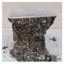  | 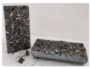 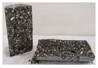 |
| RCA-3D |  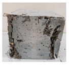 | 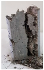 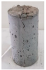 |
| RCA-5D |  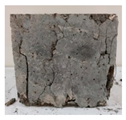 |   |
| RCA-SY |   |   |
| RCA-HY |   |   |
| Mix ID | First-Peak Strength (MPa) | % Difference * | Peak Strength (MPa) | % Difference * | Residual Strength (L/600) (MPa) | Residual Strength (L/150) (MPa) |
|---|---|---|---|---|---|---|
| RCA (Control) | 0.42 | - | 6.25 | - | ||
| Fiber reinforced RCA | ||||||
| RCA-3D | 0.43 | 2.38 | 7.73 | 23.68 | 6.27 | 4.50 |
| RCA-5D | 0.43 | 2.38 | 10.89 | 74.24 | 9.28 | 5.40 |
| RCA-SY | 0.80 | 90.48 | 6.94 | 11.04 | 5.34 | 3.65 |
| RCA-HY | 0.46 | 9.52 | 6.77 | 8.32 | 4.82 | 3.49 |
| Beam ID | (MPa) | Ultimate Load (kN) | Failure Load (kN) | Shear Load (Vc) (kN) | α * | α` | Shear Load *** % Difference | Failure Mode | Δy (mm) | Δmax (mm) | Ductility Index Δmax/Δy | |
|---|---|---|---|---|---|---|---|---|---|---|---|---|
| RCA 1 | 82.8 | 66.06 | 41.4 | Shear | 6.43 | 9.58 | ||||||
| RCA 2 | 80.6 | 64.72 | 40.3 | Shear | 7.73 | 8.85 | ||||||
| Average | 64.50 | 81.7 | 65.39 | 40.85 | 0.21 | 0.88 | - | 0.0051 | 7.08 | 9.22 | 1.3 | |
| RCA-3D-1 | 128.7 | 120.47 | 64.35 | Flexure | 6.42 | 14.58 | ||||||
| RCA-3D-2 | 140.06 | 136.28 | 70.03 | Shear- Flexure | 6.51 | 14.52 | ||||||
| Average | 68.00 | 134.38 | 128.38 | 67.19 | 0.34 ** | 1.41 ** | 64.48 | 0.0081 | 6.47 | 14.55 | 2.25 | |
| RCA-5D-1 | 130.16 | 121.96 | 65.08 | Flexure | 4.42 | 14.66 | ||||||
| RCA-5D-2 | 130.02 | 121.05 | 65.01 | Flexure | 5.50 | 14.2 | ||||||
| Average | 77.00 | 130.09 | 121.51 | 65.05 | 0.31 ** | 1.28 ** | 59.23 | 0.0074 | 4.96 | 14.43 | 2.91 | |
| RCA-SY-1 | 97.22 | 96.59 | 48.61 | Shear | 5.49 | 10.61 | ||||||
| RCA-SY-2 | 104.48 | 104.48 | 52.24 | Shear | 8.03 | 10.58 | ||||||
| Average | 64.00 | 100.85 | 100.54 | 50.43 | 0.26 ** | 1.09 ** | 23.44 | 0.0063 | 6.76 | 10.6 | 1.57 | |
| NWA-HY-1 | 123.8 | 123.8 | 61.9 | Shear | 5.36 | 19.93 | ||||||
| NWA-HY-2 | 116.4 | 116.4 | 58.2 | Shear | 7.80 | 12.64 | ||||||
| Average | 70.50 | 120.1 | 120.1 | 60.05 | 0.3 ** | 1.24 ** | 47.00 | 0.0072 | 6.58 | 11.79 | 1.79 |
| Authors | RCA% | Fibers% | Fiber | Parameters Tested | Testing Dates (Days) | Remarks | |||
|---|---|---|---|---|---|---|---|---|---|
| Compressive Strength | Tensile Strength | Flexural Strength | |||||||
| Ahmadi et al. (2017) [40] | 0%, 50%, 100% * | 0%, 1% * | Recycled Steel Fibers | −11.94% | 48.28% | 22.86% | 28 | Fibers reduced compressive strength however improved Mechanical properties | |
| Afroughsabet et al. (2017) [29] | 0%, 50%, 100% * | 0%, 1% * | Steel Fibers | 7.24% | 52.93% | 79.42% | Compressive strength at 91 remaining tests at 28 | Fibers Improved Mechanical properties | |
| Gao et al. (2017) [34] Gao et al. (2018) [30] | 0%, 100% *, 0%, 30%, 50%, 100% * | 0%, 1% *, 0%, 0.5%, 1% *, 1.5%, 2% | Steel Fibers | 4.00% | - | 12.40% | 28 | Fibers has inconsiderable effect | |
| Ahmed et.al (2020) [32] | 0%, 50%, 100% * | 0%, 0.15%, 0.3%, 0.45%, 0.6%, 0.75% *, 0.9% | Synthetic Fibers | −8.13% | −19.45% | −11.80% | 28 | Fibers reduced mechanical properties of RCA | |
| Chen et al. (2014) [27] | 0%, 100% * | 0%, 0.5%, 1% *, 1.5% | Steel Fibers | −12.12% | - | - | 28 | Reduced compressive strength of RCA | |
| Ramesh et al. (2018) [86] | 0%, 30%, 50%, 70%, 100% * | 0%, 0.3%, 0.5%, 0.7% *, 1.0% | Steel Fibers | 24.70% | 93.10% | - | 28 | Fibers Improved Mechanical properties | |
| Kazmi et al. (2019) [87] | 0%, 50%, 100% * | 0%, 0.5%, 1% * | Synthetic Fibers | 9.00% | - | - | 28 | Fibers improved the compressive strength and stress-strain curves | |
| Sayhood et al. (2019) [66] | 0%, 100% * | 0%, 0.5%, 1% *, 1.5% | Steel Fibers | 27.42% | 33.33% | 32.76% | NA | Fibers improves the mechanical properties | |
| Chaboki et al. (2019) [60] | 0%, 50%, 100% * | 0%, 1% *, 2% | Steel Fibers | −1.11% | 1.49% | - | 28 | Fibers improved shear behavior and inconsiderable effect on mechanical properties | |
| Current Study | 100% | 0.75% | 3D steel fibers | 5.43% | 72.83% | 23.65% | 90 | Fibers Improved Mechanical properties | |
| 5D steel fibers | 17.31% | 123.55% | 74.12% | ||||||
| Synthetic Fibers | −0.78% | 93.62% | 10.99% | ||||||
| Hybrid (5D + SY) | 9.30% | 141.16% | 8.30% | ||||||
| Sample # | Sample 1 | Sample 2 | |
|---|---|---|---|
| Mixes | |||
| RCA | 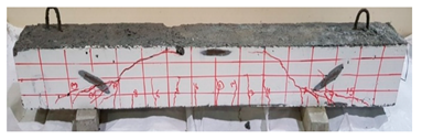 | 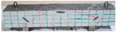 | |
| RCA-3D | 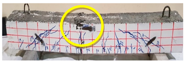 | 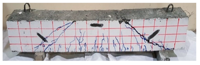 | |
| RCA-5D | 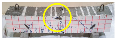 | 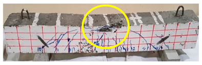 | |
| RCA-SY |  |  | |
| RCA-HY | 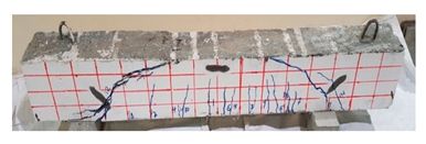 | 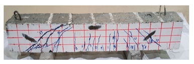 | |
| Beam | RCA 1 | RCA 2 | RCA-3D-1 | RCA-3D-2 | RCA-5D-1 | RCA-5D-2 | RCA-SY-1 | RCA-SY-2 | RCA-HY-1 | RCA-HY-2 | |
|---|---|---|---|---|---|---|---|---|---|---|---|
| Crack # | Load (kN) | ||||||||||
| 1 | 20 | 18.71 | 43.09 | 33.44 | 40.8 | 40.15 | 18.06 | 21.2 | 37.18 | 28.09 | |
| S_strain | 0.0006 | 0.0005 | 0.0009 | 0.0006 | 0.0013 | 0.001 | 0.0001 | 0.0002 | 0.0009 | 0.0005 | |
| C_Strain | 0.00005 | 0.00002 | 0.0001 | 0.0001 | 0.0001 | - | 0.0001 | - | - | - | |
| 2 | 21.05 | 19.11 | 44.9 | 34.65 | 63.59 | 41.42 | 18.88 | 24.5 | 39.05 | 29.02 | |
| 3 | 21.74 | 19.73 | 45.78 | 37.11 | 66.13 | 45.83 | 19.44 | 26.07 | 40 | 30.31 | |
| 4 | 23.25 | 21.57 | 46.51 | 42.28 | 79.57 | 51.1 | 19.89 | 29.29 | 41.44 | 32.28 | |
| S_strain | 0.0007 | 0.0006 | 0.001 | 0.0008 | 0.0026 * | 0.0012 | 0.0007 | 0.005 | 0.0011 | 0.0007 | |
| C_Strain | 0.00007 | 0.00003 | 0.0002 | 0.0001 | 0.0022 | - | 0.0006 | - | - | - | |
| 5 | 24.17 | 22.3 | 54.47 | 48.77 | 80.2 ** | 52.31 | 21.45 | 33.71 | 42.68 | 40.4 | |
| 6 | 25.18 | 36.07 | 55.48 | 56.76 | 81.38 | 52.78 | 27.53 | 38.49 | 46.11 | 44.1 | |
| 7 | 26.96 ** | 37.17 ** | 56.1 | 60.07 | 84.81 | 54.16 | 31.12 | 41.3 | 52.58 | 46.2 | |
| 8 | 30.1 | 39.27 | 57.66 | 78.46 | 90.34 | 67.66 | 33.63 | 44.42 | 55.47 | 53.4 | |
| S_strain | 0.0009 | 0.0011 | 0.0013 | 0.0018 | 0.003 | 0.0017 * | 0.0012 | 0.001 | 0.0015 | 0.0013 | |
| C_Strain | 0.0001 | 0.00003 | 0.0005 | 0.0006 | 0.002 | - | 0.001 | - | - | - | |
| 9 | 45 | 45.54 | 65.95 ** | 79.98 | 100.2 | 88.15 | 33.91 | 53.6 | 59.78 | 68.45 | |
| 10 | 47 | 65.11 | 69 | 81.24 | 118.8 | 91.26 ** | 44.23 ** | 63.8 | 69.01 | 70.31 | |
| 11 | 52.48 | 66.25 | 69.84 | 83.47 | 122.3 | 97.12 | 54.05 | 66.07 ** | 81.84 | 71.49 | |
| S_strain | 0.0016 | 0.0019 | 0.0017 | 0.0019* | 0.0048 | 0.0013 | 0.0018 | 0.0016 * | 0.0022 * | 0.0017 | |
| C_Strain | 0.0004 | 0.0061 | 0.001 | 0.0007 | 0.0029 | - | 0.0024 | - | - | - | |
| 12 | 62.1 | 68.36 | 75 | 85.91 ** | 122.3 | 98.03 | 70.32 | 80.7 | 83.28** | 76.09 | |
| 13 | 63.63 | 78.22 | 101.1 | 122.9 | 101.6 | 88.92 | 82.4 | 85.51 | 81.42 ** | ||
| 14 | 64 | 79.5 | 115.4 | 124 | 102.4 | 79.1 | 100.4 | 83.56 | |||
| 15 | 68.8 | 93.7 | 135.3 | 124.4 | 112.4 | 114.6 | 88.2 | ||||
| 16 | 99.9 | 135.3 | 125.8 | 126.5 | 97.69 | ||||||
| 17 | 100.3 | 136.1 | 128.3 | 127.7 | 101.2 | ||||||
| S_strain | 0.0025 * | 0.011 | 0.015 | 0.011 | 0.0026 * | ||||||
| C_Strain | 0.0034 | - | 0.0031 | ||||||||
| 18 | 101.5 | 106.9 | |||||||||
| 19 | 105.3 | 115.7 | |||||||||
| 20 | 119.95 | ||||||||||
| 21 | 121.6 | ||||||||||
| 22 | 121.9 | ||||||||||
© 2020 by the authors. Licensee MDPI, Basel, Switzerland. This article is an open access article distributed under the terms and conditions of the Creative Commons Attribution (CC BY) license (http://creativecommons.org/licenses/by/4.0/).
Share and Cite
Ghoneim, M.; Yehia, A.; Yehia, S.; Abuzaid, W. Shear Strength of Fiber Reinforced Recycled Aggregate Concrete. Materials 2020, 13, 4183. https://doi.org/10.3390/ma13184183
Ghoneim M, Yehia A, Yehia S, Abuzaid W. Shear Strength of Fiber Reinforced Recycled Aggregate Concrete. Materials. 2020; 13(18):4183. https://doi.org/10.3390/ma13184183
Chicago/Turabian StyleGhoneim, Mohamed, Ayatollah Yehia, Sherif Yehia, and Wael Abuzaid. 2020. "Shear Strength of Fiber Reinforced Recycled Aggregate Concrete" Materials 13, no. 18: 4183. https://doi.org/10.3390/ma13184183
APA StyleGhoneim, M., Yehia, A., Yehia, S., & Abuzaid, W. (2020). Shear Strength of Fiber Reinforced Recycled Aggregate Concrete. Materials, 13(18), 4183. https://doi.org/10.3390/ma13184183