1. Introduction
Metallic implants are frequently used in medical applications. Typical examples are medical stents, bone plates, and screws, as well as joint implants. In addition to conventional processing like forging and machining, sintering is applied for the fabrication of these implants in an increasing number of applications [
1,
2,
3]. The motivation is either achievement of special material properties or application of modern shaping technologies related to the usage of fine metallic powders. These technologies provide the possibility to individualize implants to the needs of distinct patients, e.g., bone plates for fracture stabilization. These processes usually require a so-called feedstock material with a sufficiently high volume fraction of metallic powder particles which is mixed with a binder consisting of different polymers. A green body can be prepared from this feedstock, e.g., using the method of metal injection molding (MIM) [
4,
5]. Injection molding is typically associated with a high pressure on the order of several hundred bar during injection. Furthermore, a special mold, which is usually quite expensive, is needed for the MIM process. After injection molding, the polymers are typically removed from the green part by chemical or solvent debinding and a subsequent thermal process, after which the powder is sintered to the final pure metallic component. High pressures and the use of a mold both lead to some advantageous properties, including a smooth surface of the green body and accurate geometrical dimensions. Voids can also be avoided to a large extent in the MIM process. Metal injection molding has been an established cost-effective production process for several decades, and it is typically used to manufacture large volumes of small complex-shaped parts. However, for small quantities, the high expenses for the mold make the technology less attractive. Therefore, other techniques adapted from additive manufacturing technologies related to the usage of feedstock are under development to enable the shaping of single parts or small series [
6,
7,
8,
9,
10].
Recently, fused filament fabrication (FFF) was used to prepare green bodies for sintering [
11,
12,
13,
14,
15]. In contrast to MIM, where the feedstock is provided as granules, here, the feedstock material is needed in a filament form. In comparison to the equipment used for the MIM process, the costs for installation of the FFF equipment are much lower. In addition, a nearly unlimited variety of geometries can be achieved using the FFF process without the design of an expensive mold. However, processing of feedstock materials is much more challenging than printing pristine polymers which are typically used for fused filament fabrication, since the feedstock materials need to have a sufficiently high fraction of metallic powder particles. Consequently, only a very small number of polymers filled with metal powder particles are currently commercially available, with commercial products mainly focusing on stainless-steel powders. In addition to optimum flow properties, feedstock filaments for the FFF process need to possess a certain degree of flexibility such that they can be spooled and bent easily. Furthermore, possible detrimental reactions between binder residuals and the metallic powders during thermal debinding and sintering have to be considered [
16]. This is especially true for highly reactive materials like titanium and magnesium [
17]. Therefore, a variety of conditions have to be fulfilled such that a feedstock can be successfully used for both fused filament fabrication and subsequent sintering of a metallic part.
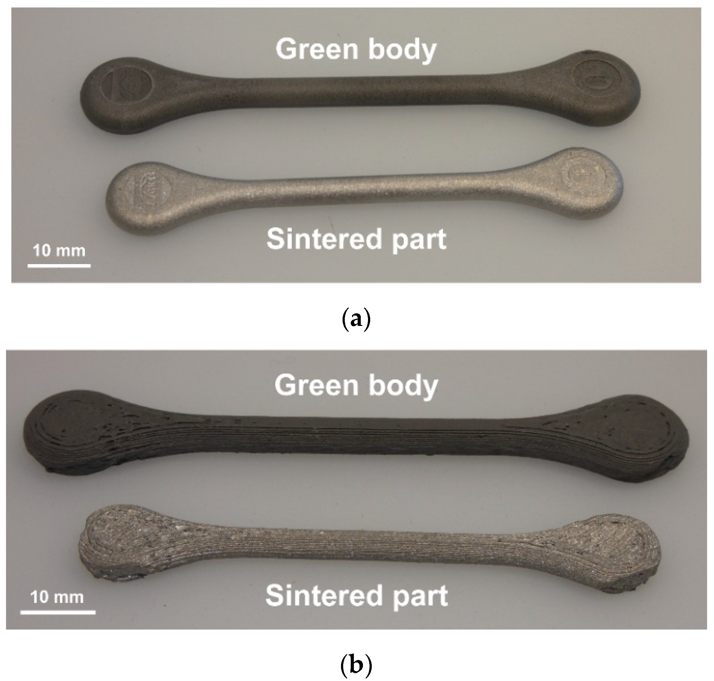
The use of filaments made from filled polymers for metallic implants is a relatively novel approach for the preparation of green bodies. Nevertheless, the quality of printed parts (e.g., their smoothness) has to be increased and the reproducibility of the process has to be improved (see
Figure 1). The FFF process can be divided into three main steps associated with different thermal and deformation rate conditions: (i) the feeding of the solid filament into the liquefier, (ii) the flow of the feedstock melt in the nozzle, and (iii) the deposition and subsequent solidification of the feedstock melt on the existing layer of the printed part. An overview of the process design and modeling was given by Turner et al. [
18]. In the first step (i.e., the feeding of the filament into the liquefier), buckling of the filament may occur. A buckling criterion was derived by Venkataram et al. [
19] which considers the ratios of tensile modulus and viscosity of the used polymer. The melt flow in the nozzle was thoroughly described in the work of McIlroy and Olmsted [
20]. On the contrary, only a few studies focused on the last step, i.e., the deposition and solidification of the extruded melt.
Generally, binder and feedstock materials consist of several components which are necessary for fused filament fabrication and sintering, serving as shaping aids and mechanical stabilizers through the different steps of the processing chain. It is well known that the rheological properties of polymeric materials influence their behavior in processing, e.g., phenomena like strain hardening in melt elongation and shear thinning [
21]. Consequently, several investigations are devoted to the influence of the rheological properties of pristine polymers on their processing behavior in fused filament fabrication. The failure feed velocity that limits the maximum extrusion rate was determined by Mackay et al. [
22]. In the work of Phan and coauthors [
23], a model taking into account rheological and heat transfer effects in the nozzle flow of an FFF printer was analyzed. Their work quantified the heat transfer effects limiting the manufacturing rate. A recent overview of this topic with an emphasis on pristine polymer melts was given in the review of Mackay [
24]. In addition, modeling studies were performed, showing that the deposition process disentangles the polymer melt [
20]. Furthermore, in-line rheological methods were applied in order to monitor the FFF process, and their validity for characterization of new materials for FFF printing was shown [
25]. A variety of studies focused on the improvement of different polymeric materials for three-dimensional (3D) printing, e.g., the work by Nguyen et al. [
26], which used carbon fibers to improve the mechanical properties of the printed part. In a recent publication, a novel approach was presented to evaluate feedstock compositions for metal fused filament fabrication [
27]. The authors stated that the shear force that was estimated on the basis of the shear strength of the filament was the key parameter determining successful printing. In the work of Seppala and Migler [
28], the decrease in weld temperature was experimentally determined. Their work showed that the melt stays above the glass transition temperature for only approximately 1 s.
Despite these studies, there are still many open questions in practice. In addition to purely technical issues such as reliable transport of the filament by the printer, heat transfer, sticking on the build plate, and further issues, the complexity of binder composition, powder size distribution, powder surface, and chemical reactions with the metal make the prediction of the optimal filament properties and binder composition very difficult. In practice, changing one component usually means a need for a comprehensive set of experimental trials. Therefore, more basic research is needed in all steps of the metal FFF process. This work provides a first step in this direction by aiming to link the rheological and printing properties of feedstocks that are of relevance for medical implants. Therefore, thermal analysis, rheological experiments, and analysis of printing behavior were performed in this work.
In this work, we focus on the flow and printing properties of selected feedstock materials, i.e., their properties in the melt state. Several in-house designed feedstock materials with different amounts of titanium particles were used for the experimental investigations, and a practical ring geometry for analysis of FFF printing properties was taken. Titanium was selected because of its relevance for medical implants. In addition, a standard 3D printing material, a grade of the linear homopolymer polylactide, was chosen as a reference material. All feedstock materials fulfilled the criteria of printability using FFF, and they were deemed debindable and sinterable if the volume concentration of titanium particles was equal or larger than 50%. The objective of this study was to evaluate the flow properties of feedstock materials for optimum processing.
2. Materials and Methods
In this study, a commercial homopolymer and a specially designed series of feedstocks were chosen for the experimental investigations. A pristine polylactide (PLA, REC, Moscow, Russia) was used as a standard commercial reference material for fused filament fabrication. Furthermore, a series of feedstocks with varying amounts of titanium particles were prepared for a systematic analysis. The binder components are listed in
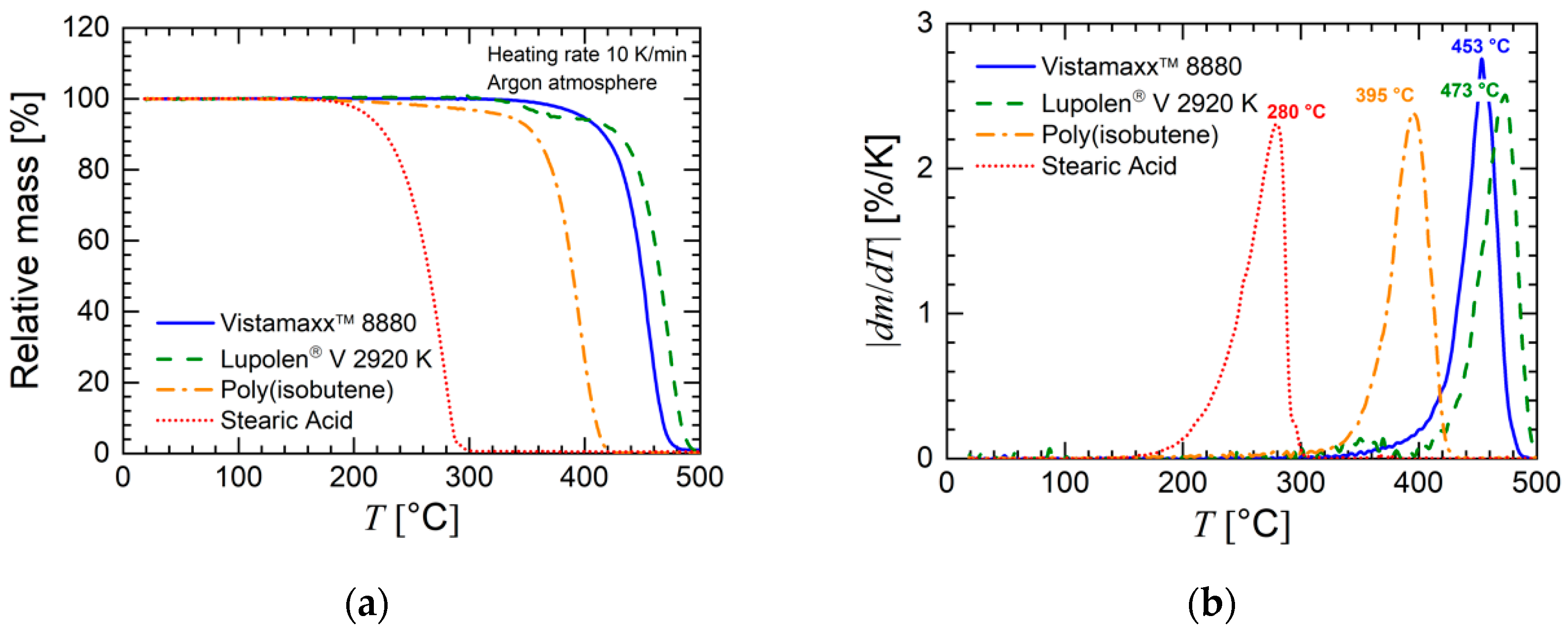
Table 1 and consist of a poly(propylene–ethylene) copolymer composed of isotactic propylene repeat units and a random ethylene distribution, a poly(ethylene–vinyl acetate) copolymer, poly(isobutene), and stearic acid. The volume concentration of the titanium particles ranged from 0% to 60% in increments of 10%. In addition, a feedstock with 65 vol.% titanium particles, which is the standard amount of MIM feedstocks and also close to the critical loading for spherical particles, was also prepared.
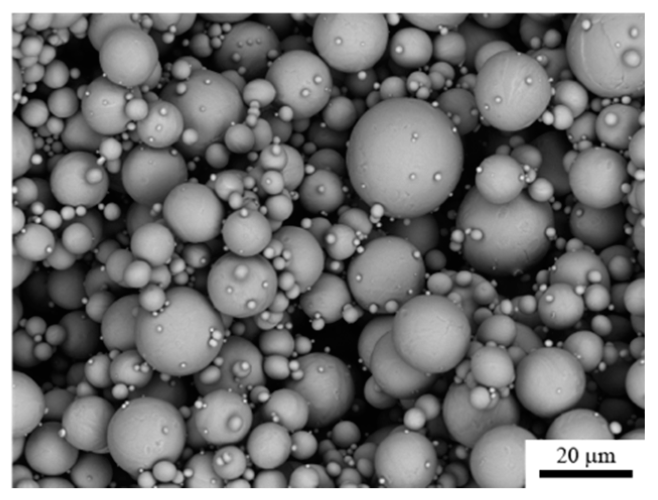
The chosen metal essentially determines the properties of the final part and, thus, plays a dominant role in processing. For the in-house prepared series of feedstocks, gas-atomized spherical Ti-6Al-4V alloy powder (density 4.5 g/cm3, particle diameter <20 μm, Advanced Powders & Coatings, Boisbriand, QC, Canada) was chosen, hereinafter referred to as titanium in general for ease of reading. Generally, titanium is characterized by a high strength and biocompatibility.
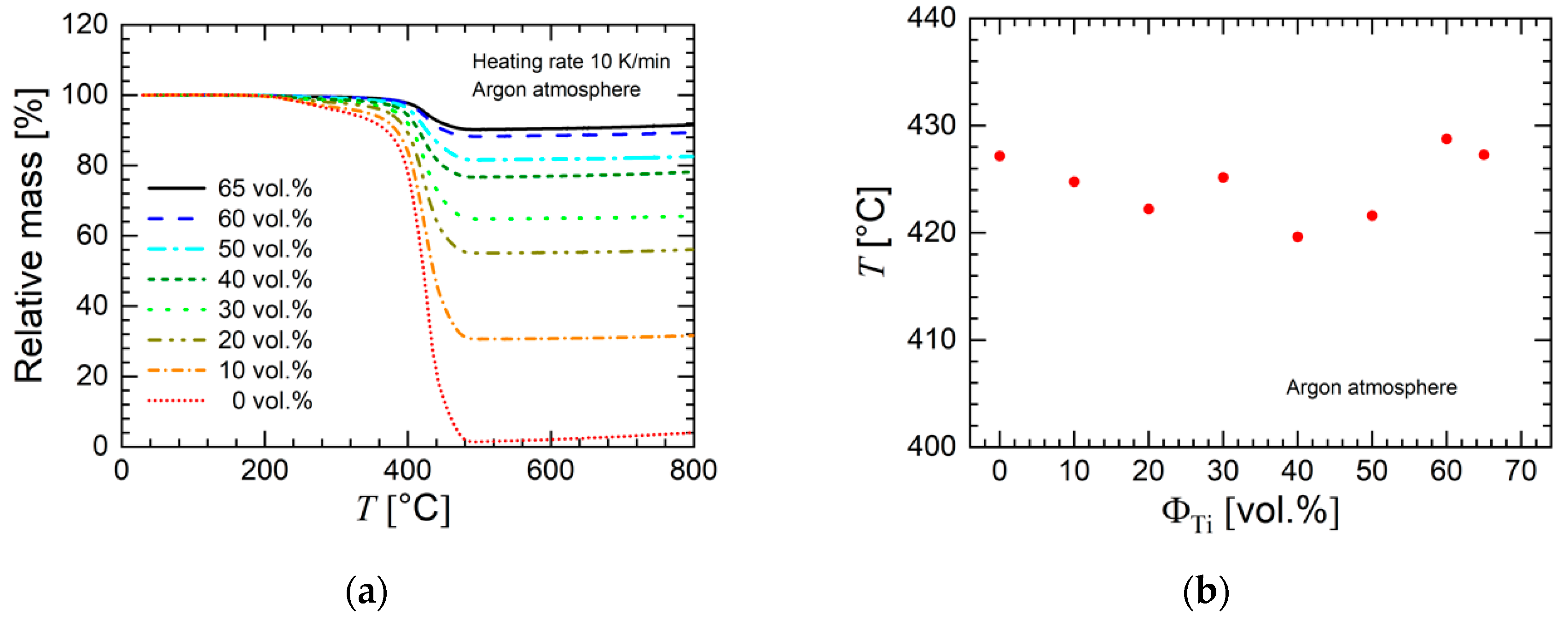
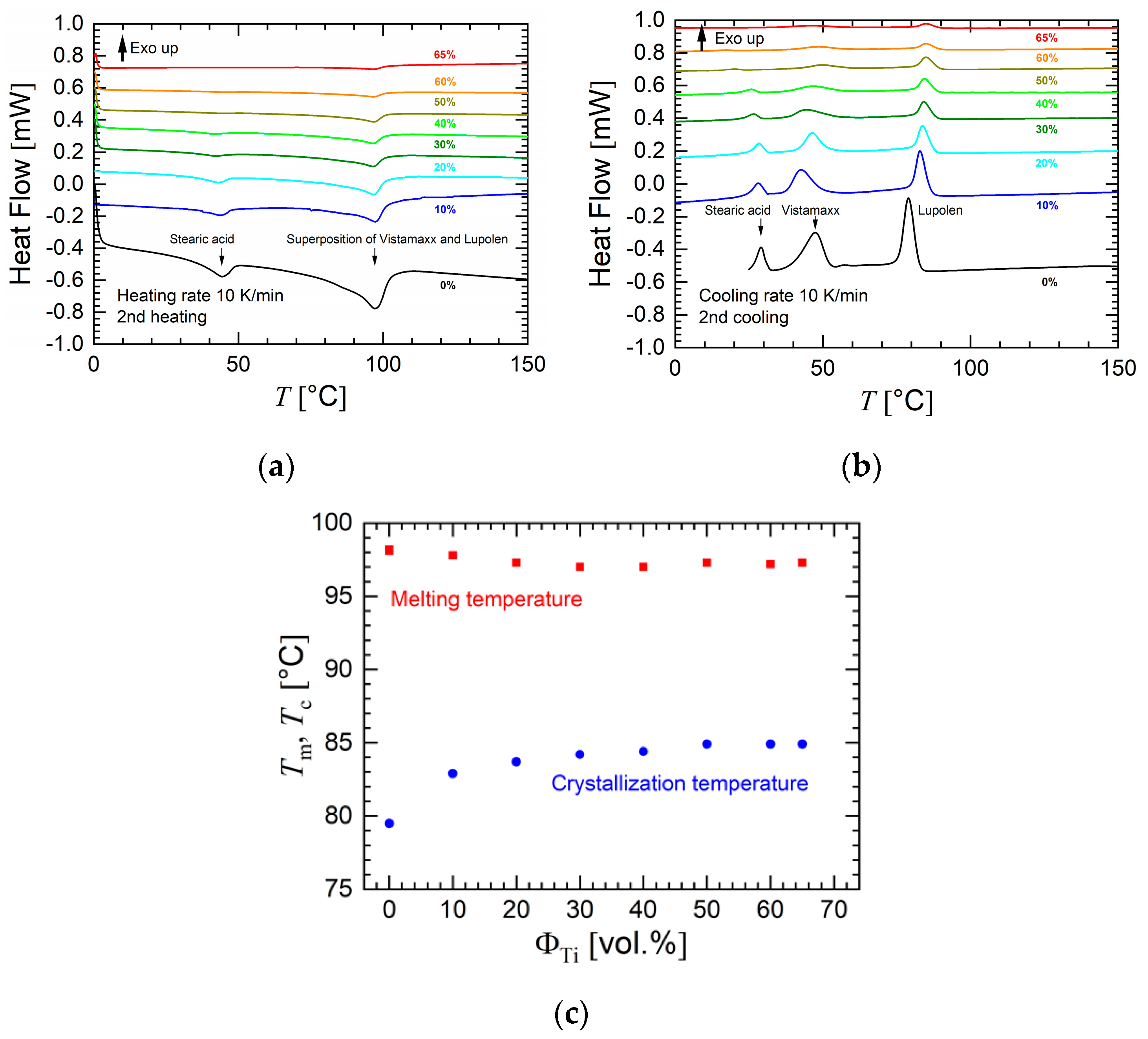
In order to achieve a complete evaluation of the mixing process, the feedstock properties, and printing behavior, a comprehensive material characterization was undertaken. Before the tests, all samples were stored under vacuum at a temperature of 30 °C. Thermalgravimetric analysis (TGA) was performed using a TG 209 F1 Libra® (Netzsch, Selb, Germany). The heating rate was 10 K/min, and an argon atmosphere was applied. Differential scanning calorimetric (DSC) experiments were carried out using a DSC 1 Stare System (Mettler-Toledo, Greifenberg, Switzerland). This heating rate was also 10 K/min. The experiments were performed in a nitrogen atmosphere. A heating–cooling–heating cycle was applied. The first heating cycle ranged from room temperature to a temperature 60 °C above the highest melting temperature Tm of the material. The subsequent cooling run went to –150 °C, and the final heating cycle ranged from −150 °C to Tm 60 °C. The thermal transitions were determined on the basis of the second heating cycle.
Samples for the rheological tests were prepared by means of compression molding. The cylindrical samples had dimensions of 8 mm diameter by 2 mm thickness (PLA) or 14 mm diameter by 1 mm thickness for the in-house designed feedstocks. Before compression molding, the samples were dried under vacuum at a temperature of 30 °C. The samples were created via a hot-press compression molding device (Paul-Otto Weber, Remshalden, Germany). The hot press applies a high compressive force of approximately 60 kN. The compression molding temperature varied for the different materials (200 °C for PLA and 120 °C for the in-house designed feedstocks).
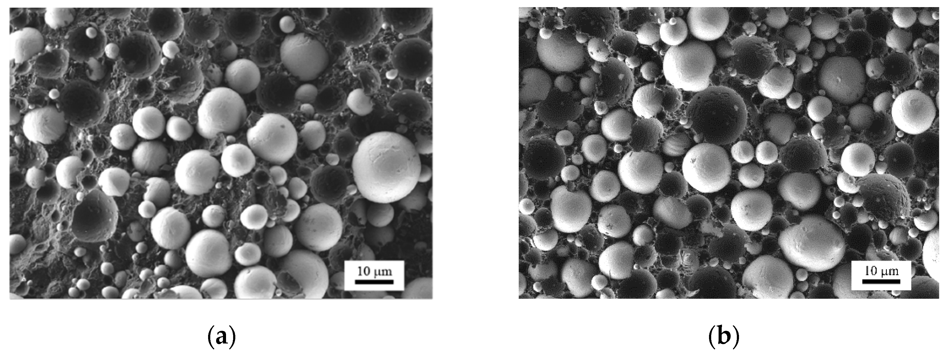
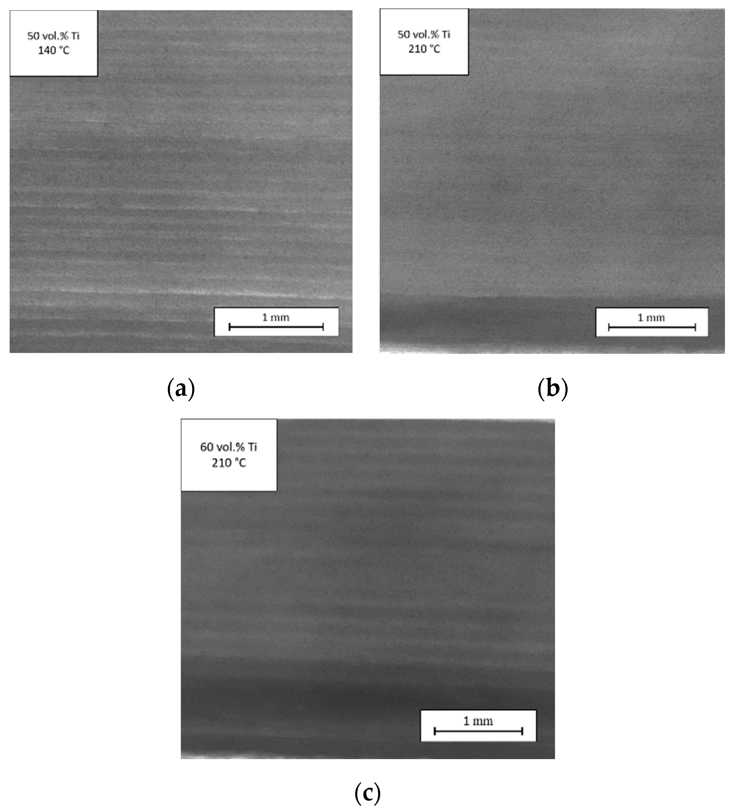
Microscopic investigations of the titanium powder were performed on a “Tescan Vega3 SB” (TESCAN, Brno, Czech Republic) scanning electron microscope (SEM) in backscattered (BSE) mode using a work distance of 10 mm and an accelerating voltage of 13 kV. Scanning electron microscopy investigations of the feedstock materials were completed to get a rough impression for the homogeneity of compression-molded samples with respect to the powder particle distribution within the polymer binder matrix. This imaging was performed using a scanning electron microscope (Merlin, Zeiss, Oberkochen, Germany) in BSE mode. The acceleration voltage was 3.0 kV. For investigations of the cross-sections, the samples were fractured in liquid nitrogen.
A blend of polymers and additives, called a binder material, was used and mixed with the metal powder in order to facilitate processing of the pristine metal powder. To evaluate the dependence of rheological and printing properties on the powder load, eight different feedstocks were prepared using titanium powder, i.e., with 0, 10, 20, 30, 40, 50, 60, and 65 vol.% metal powder.
The process of mixing the metal powder with the binder material utilized a planetary mixer (THINKY Inc., Laguna Hills, CA, USA) and either a hot plate or an oven. First, the primary polymers and nonprimary polymers were mixed together in a metal mixing canister (
Table 1). The mass of each component was measured as it was mixed to ensure the proper ratios. Then, air was removed from the canister before it was placed inside a glove-box system (M. BRAUN INERTGAS-SYSTEME GMBH, Garching, Germany) with controlled argon atmosphere, in which the mass of the metal powder could be measured and mixed. The canister was subsequently covered and brought to the oven (Memmert, Schwabach, Germany), where it was heated above the melting temperature of the polymers. Afterward, the canister was removed from the oven and placed into a planetary mixer where powder and binder were mixed for 5 min until the blend appeared smooth and homogeneous. The homogenous melt was cooled and subsequently ground into pellets to be used in the extruder. The extruder (Collin, Teach Line E 20 T, COLLIN Lab & Pilot Solutions GmbH, Maitenbeth, Germany) was used in tandem with a conveyer belt to create the desired filament with a diameter of approximately 2.7 mm. The
L/
D ratio of the extruder was 25, and the diameter of the cylindrical die was 3 mm.
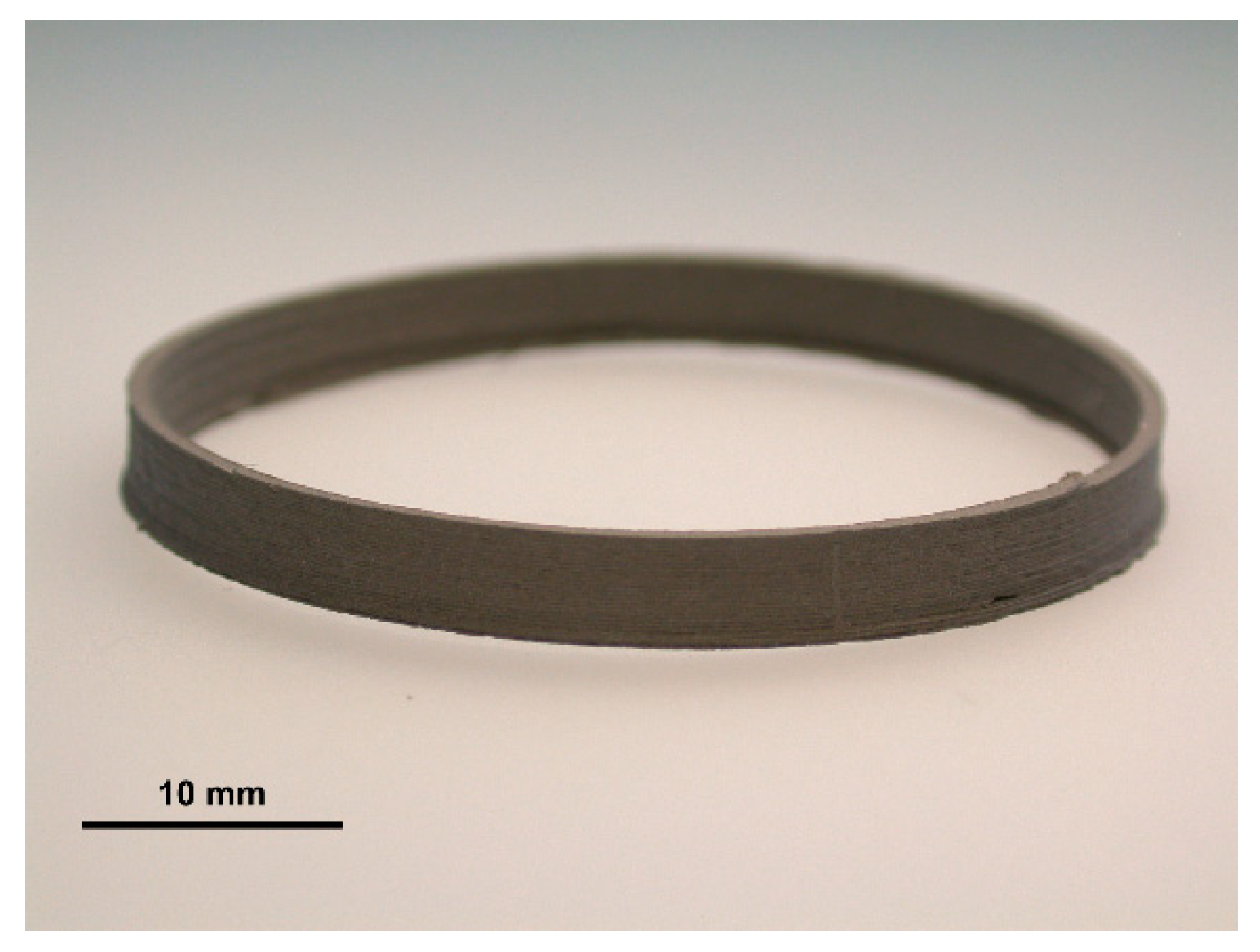
Rings with a target geometry consisting of a 40 mm outer diameter, a wall thickness of 0.8 mm, and a height of 4 mm were produced on the Ultimaker 3 (Ultimaker B.V., Utrecht, the Netherlands) printer using a nozzle diameter of 0.8 mm (see
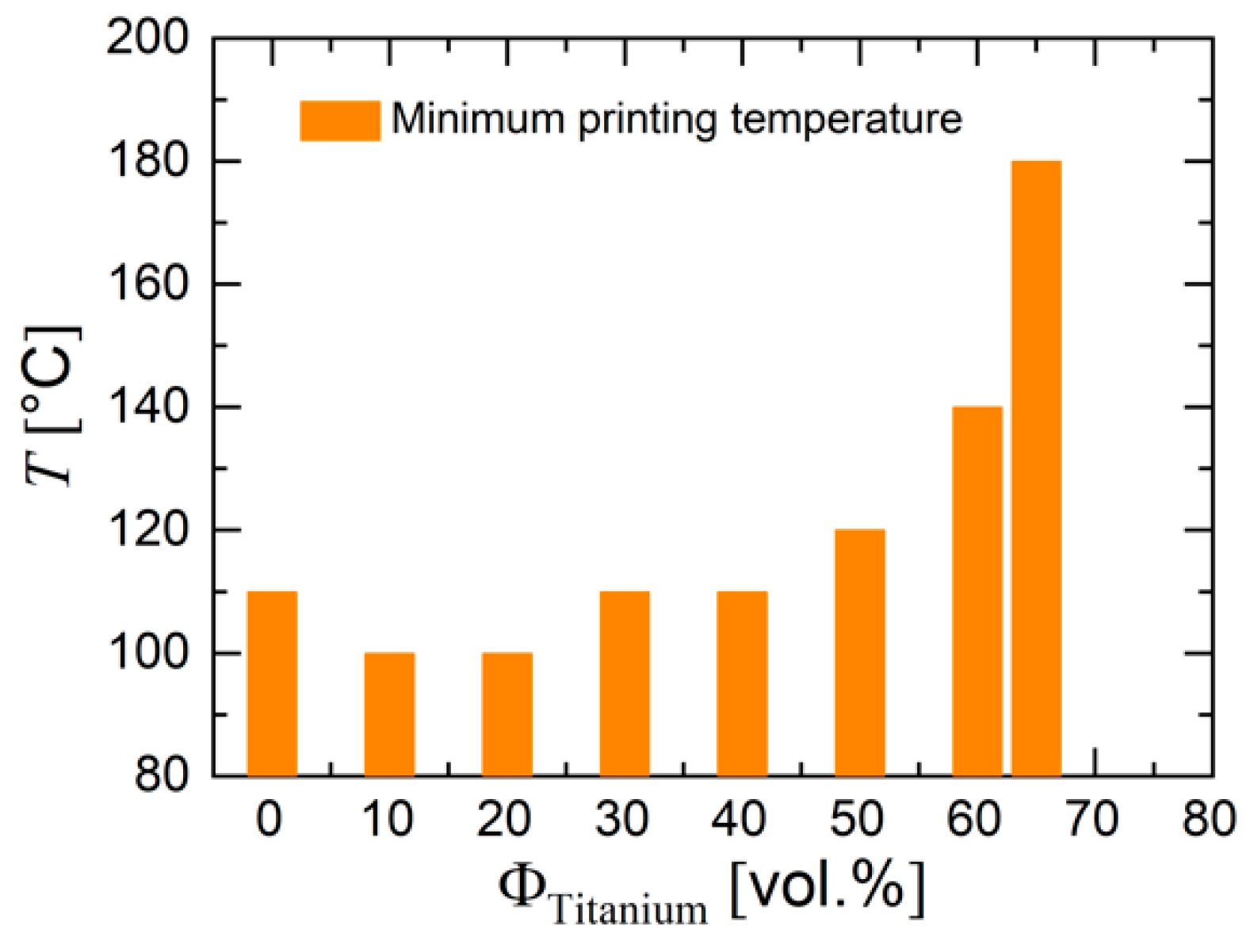
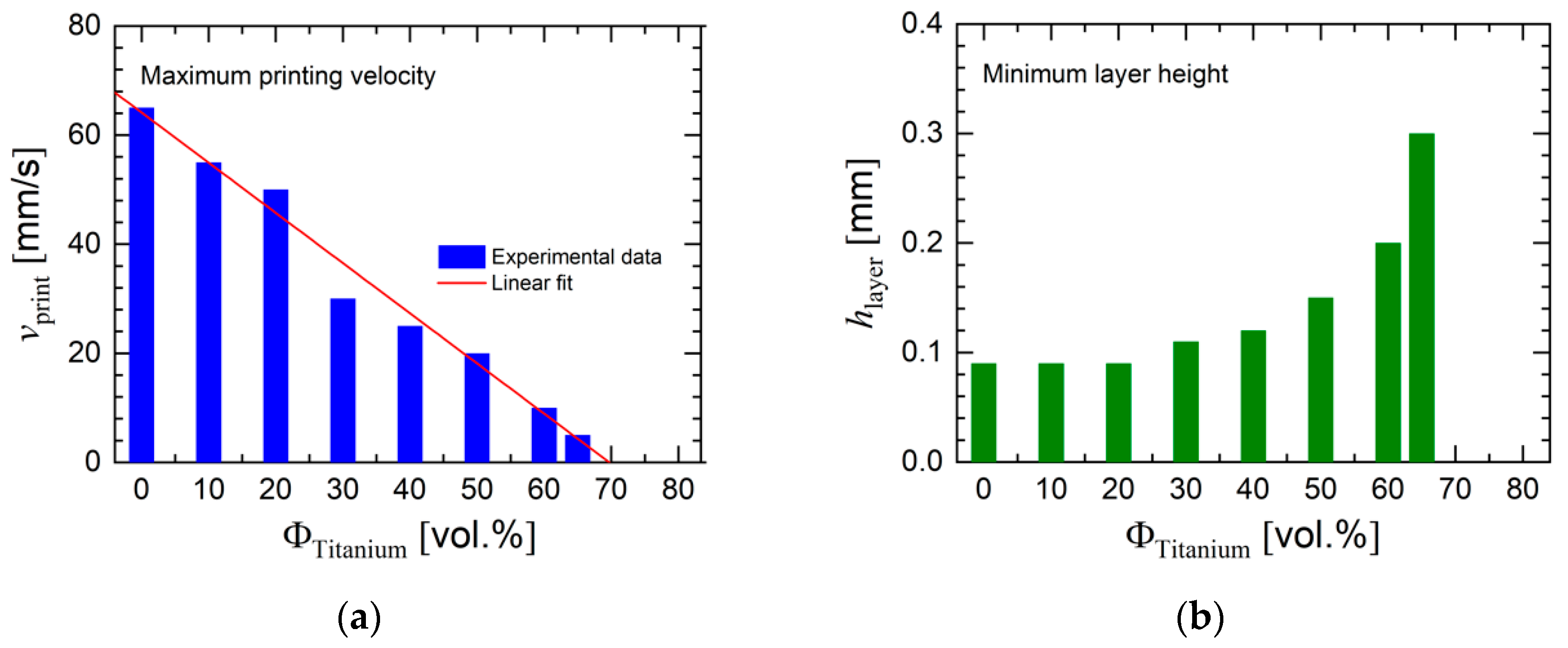
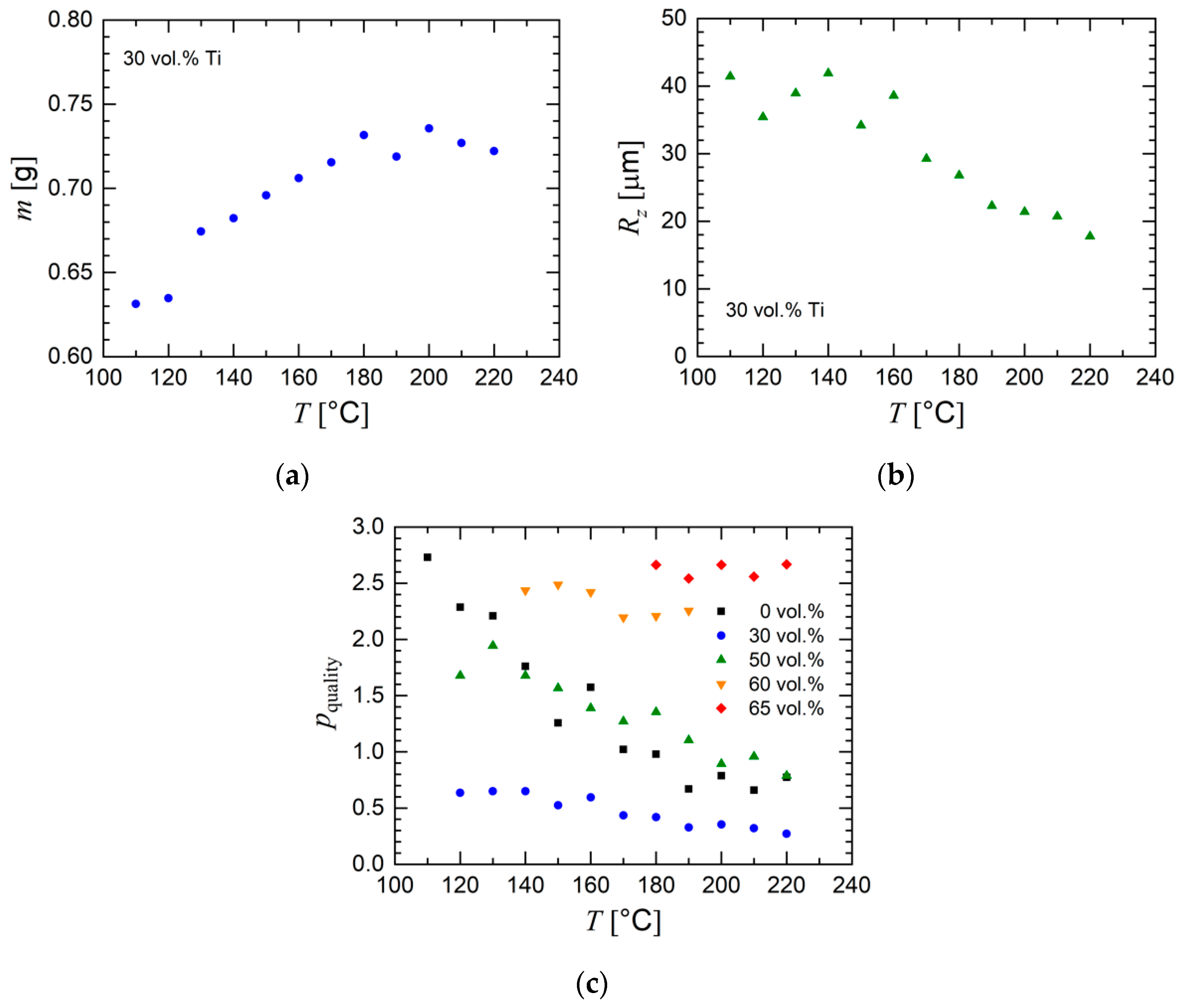
Figure 2). The ring geometry was chosen as a well-defined test geometry which can be printed with constant flow rate, mimics thin elements of implants because of its thin wall structure, and provides a few benefits. A simple geometry is easy to measure (diameter, height, and wall thickness) and large enough that any changes in volume can be easily detected. The thin wall also makes it easy to observe surface issues. In addition, the print can be produced via a continuous extrusion process. If an untested filament was loaded into the printer, then initial printing tests were completed by holding all printing parameters constant and only changing one variable at a time. The most important parameters were determined to be nozzle temperature, layer height, flow, and printing velocity. The initial printing involved finding the smallest layer height in combination with the fastest printing speed that was able to produce parts. These two parameters are necessary to be determined since a smaller layer height aids in the final surface finish and a fast printing speed keeps production time low. After stable prints could be made, a temperature sweep was started. The parameters determined from the initial printing were held fixed, while the temperature was changed in increments of 10 °C, within the range of 100 to 220 °C. The lower limit was determined from the melting temperature of the polymers and the upper temperature limit was defined by the 3D printer. Printing would continue until the entire range was covered or until the prints would fail at a given temperature. After each ring was printed, its geometry was measured using calipers. The outer diameter, wall thickness, and overall height were measured and recorded (estimated accuracy of the caliper, 50 μm). Each geometric feature was measured at five different locations along one ring. The measurements were averaged and used to evaluate the temperature effects. Other qualitative properties for each ring were also taken note of, such as surface quality, build plate adherence, and warping.
The density of the printed rings was measured and compared to the theoretical value calculated from the composition of the feedstock and the density of the single components. The density was determined with an analytical balance (LA 230 S, Sartorius, Göttingen, Germany) on the basis of Archimedes’ principle. First, after calibration using a ball bearing with a known mass, volume, and density, a ring sample was placed on the balance, and its weight was measured first in air and afterward in the fluid. Then, the balance device output the density of the given ring.
The roughness was measured with the MarSurf SD 26 (Mahr, GmbH, Göttingen, Germany) via a contact probe. The roughness values Ra (average roughness around the mean line of the tested area) and Rz (average of differences of maximum and minimum in test intervals) were determined at five separate locations on the ring and averaged. The probe was dragged 1.5 mm along the surface of the ring from the base of the print to the top surface at a velocity of 0.1 mm/s.
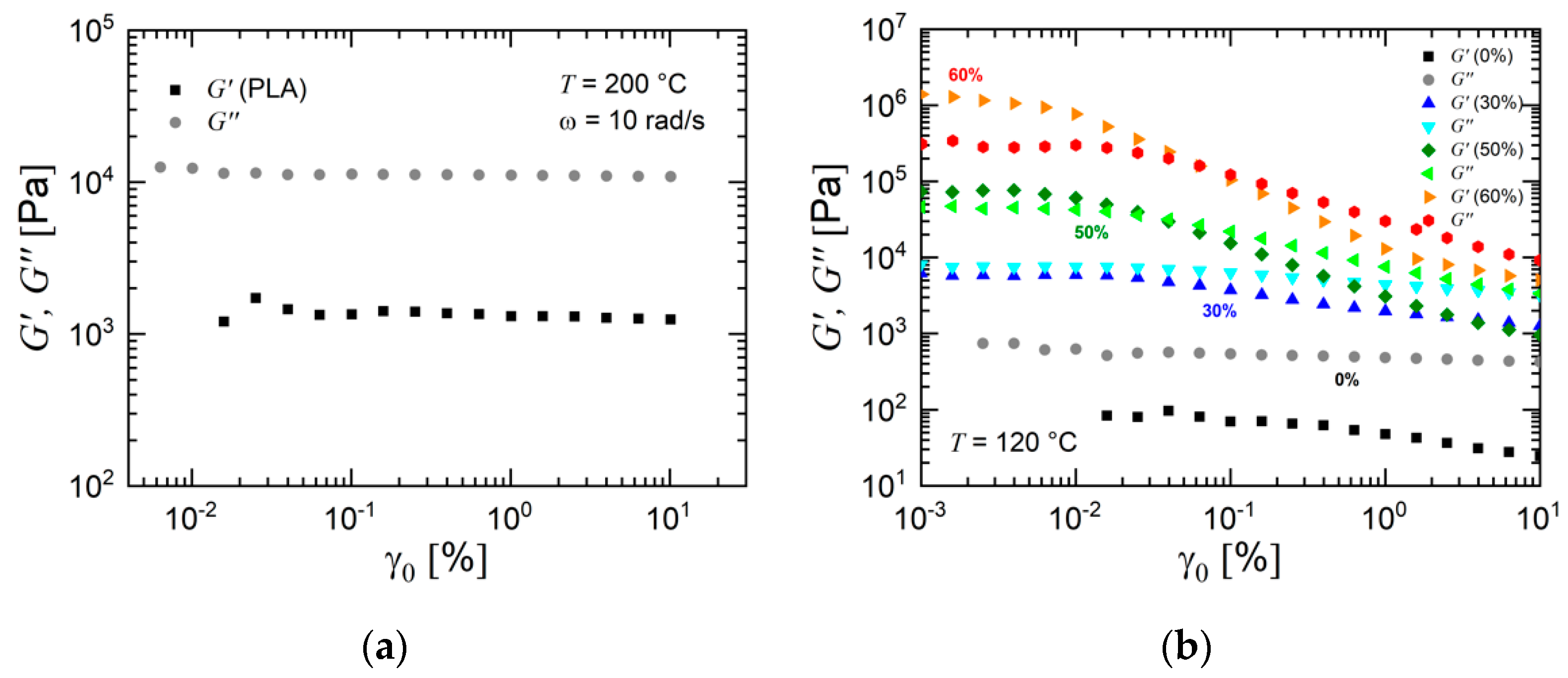
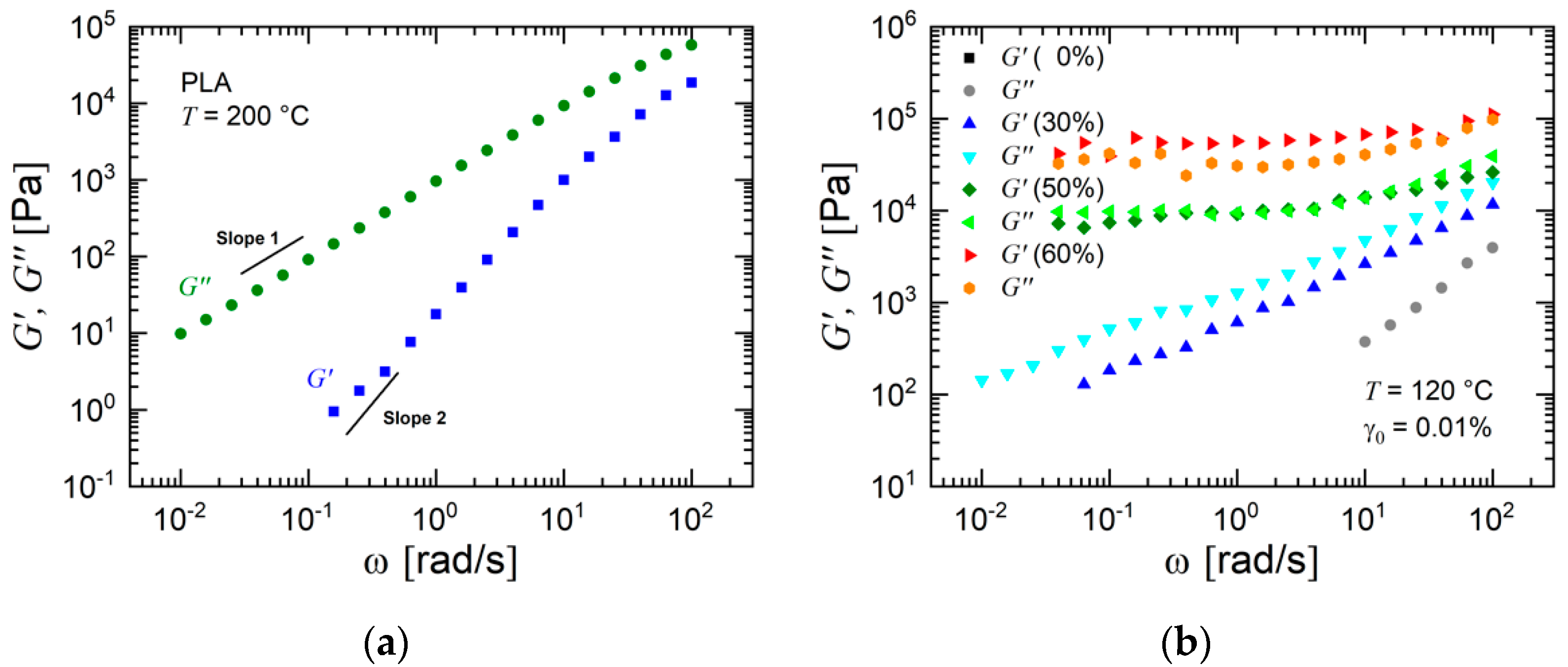
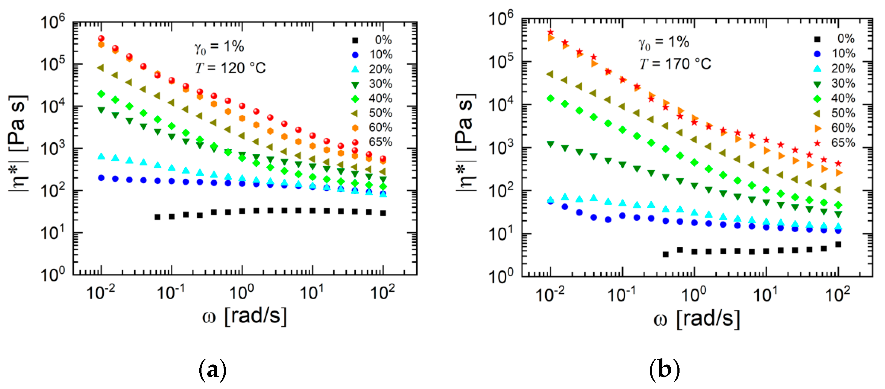
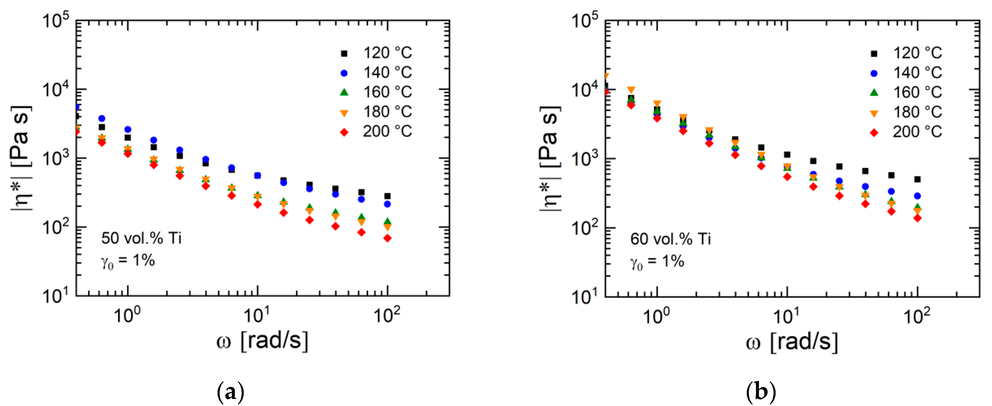
The rheological experiments using the binder and the feedstock materials were performed using a rotational rheometer (MCR 502, Anton Paar, Graz, Austria) in oscillatory mode. A plate–plate geometry with a sample diameter of 8 mm (PLA) or 14 mm (binder and feedstocks) was used, and a nitrogen atmosphere was applied. For temperature equilibration, a waiting time of 8 min was chosen. First, a strain sweep in the range of 0.001% to 10% at an angular frequency of 10 rad/s was performed in order to determine the linear viscoelastic range. Then, a frequency sweep in the range from 0.01 to 100 rad/s (starting at the highest angular frequency) at constant strain amplitude γ0 was carried out.

 ,
, 


