Fabrication and Tribological Properties of Mesocarbon Microbead–Cu Friction Composites

Abstract
:1. Introduction
2. Experimental
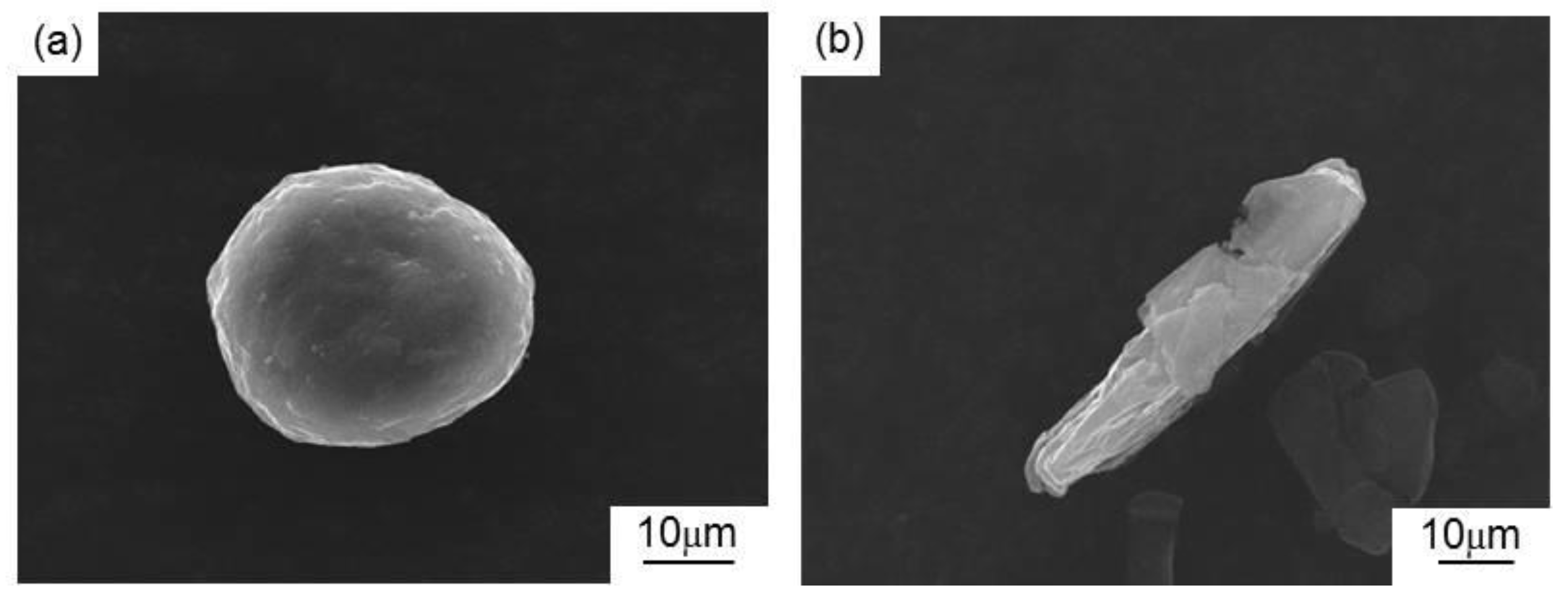
2.1. Materials
2.2. Preparation Method
2.3. Characterizations
3. Results and Discussion
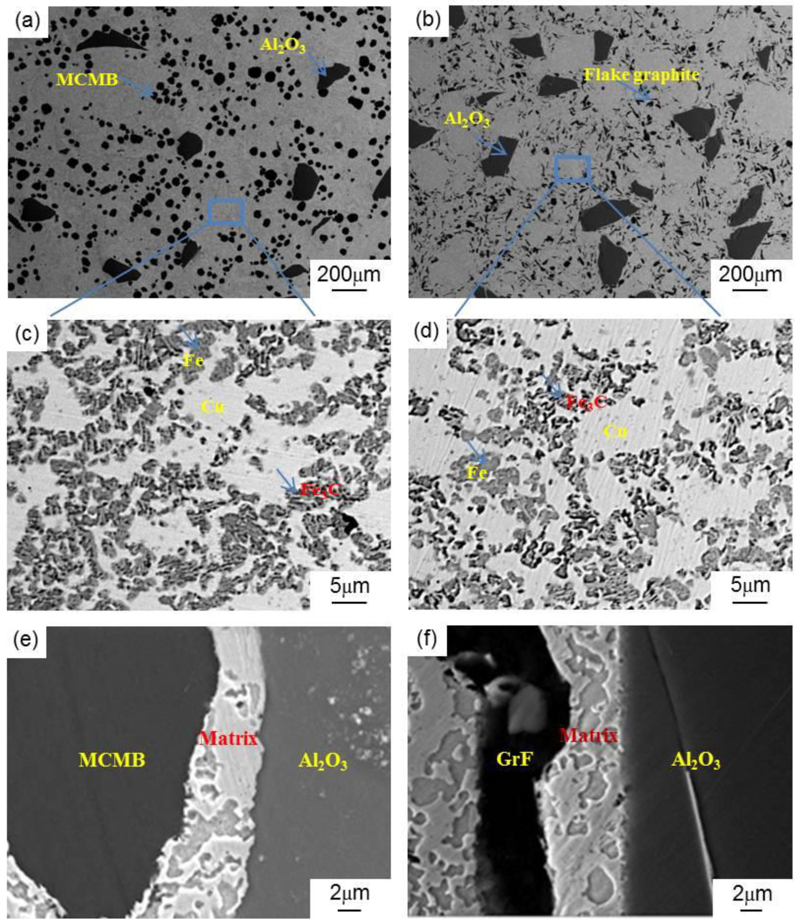
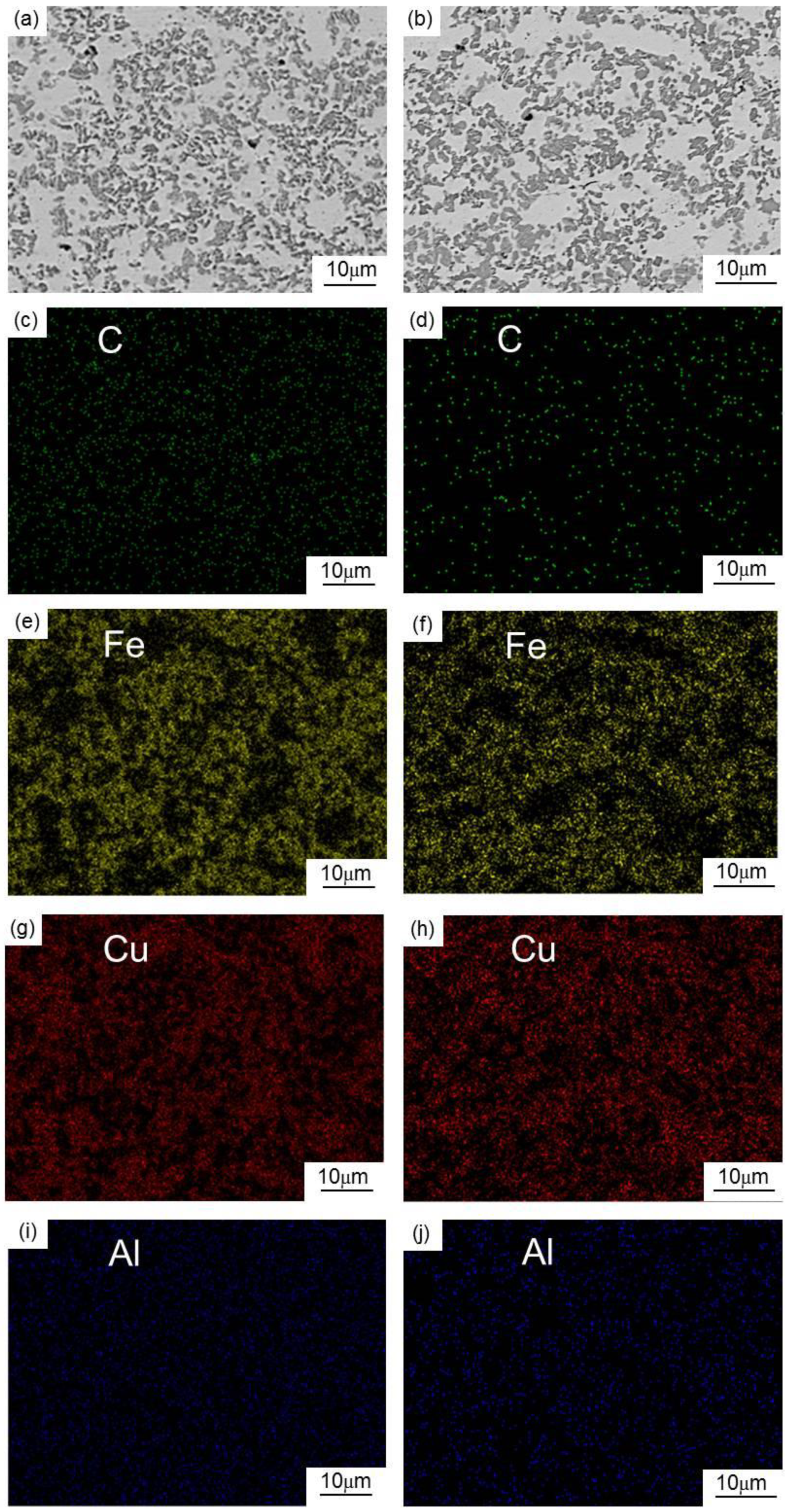
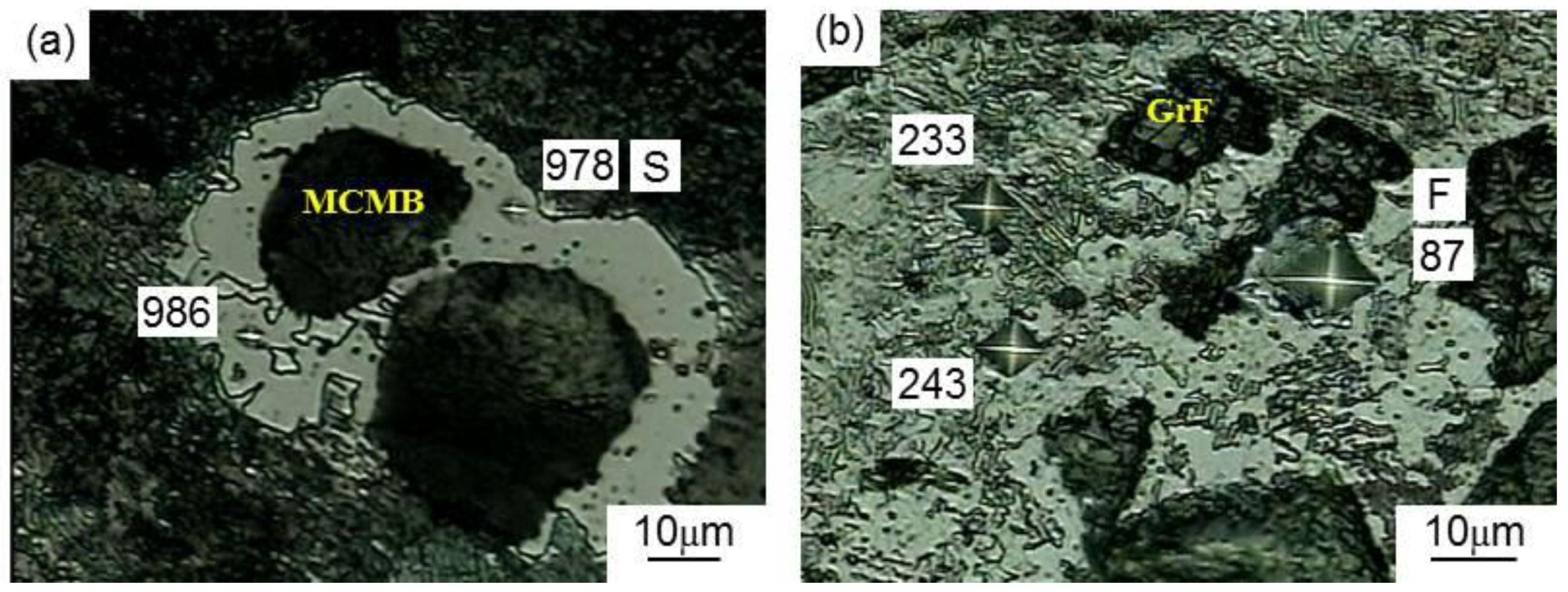
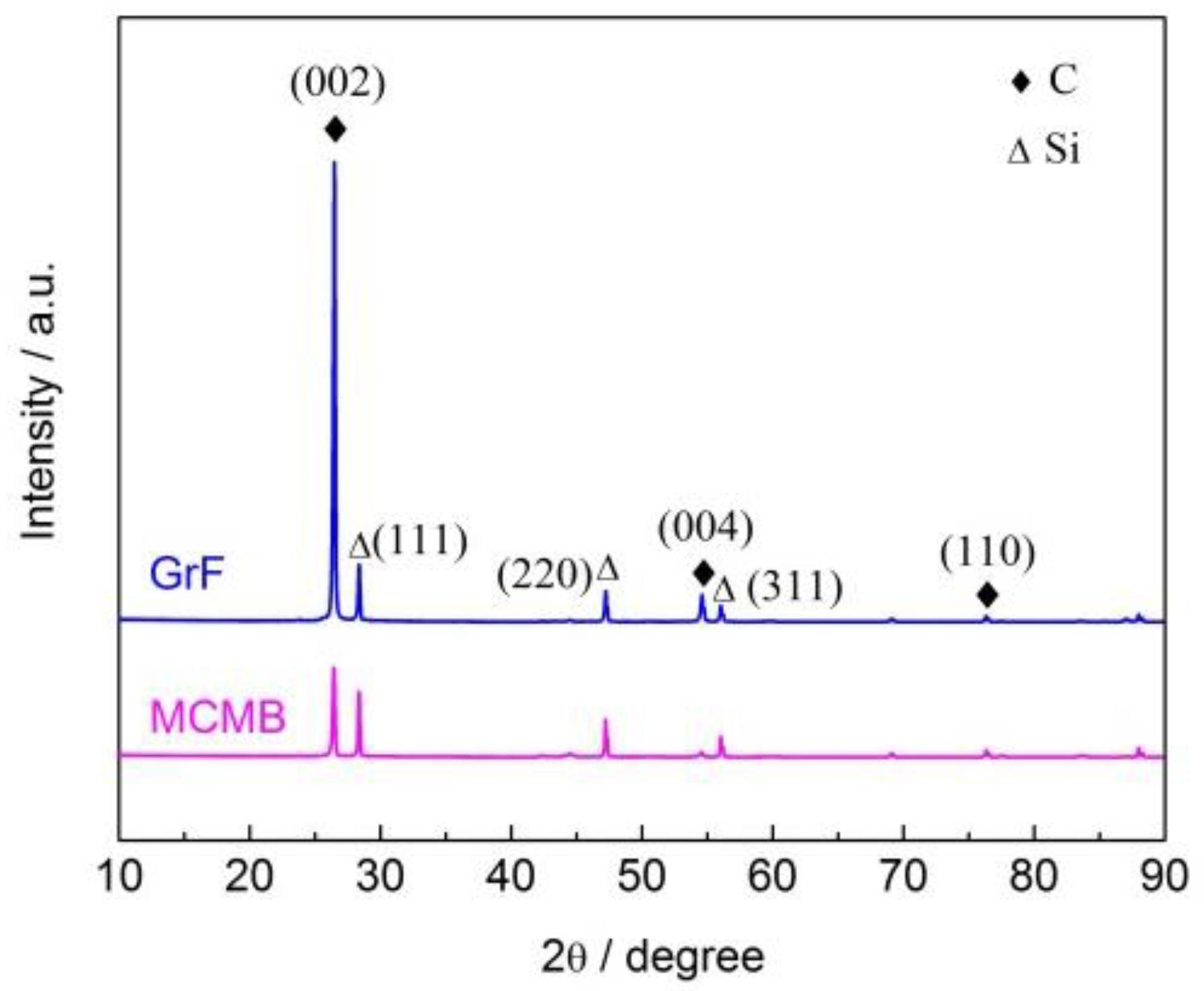
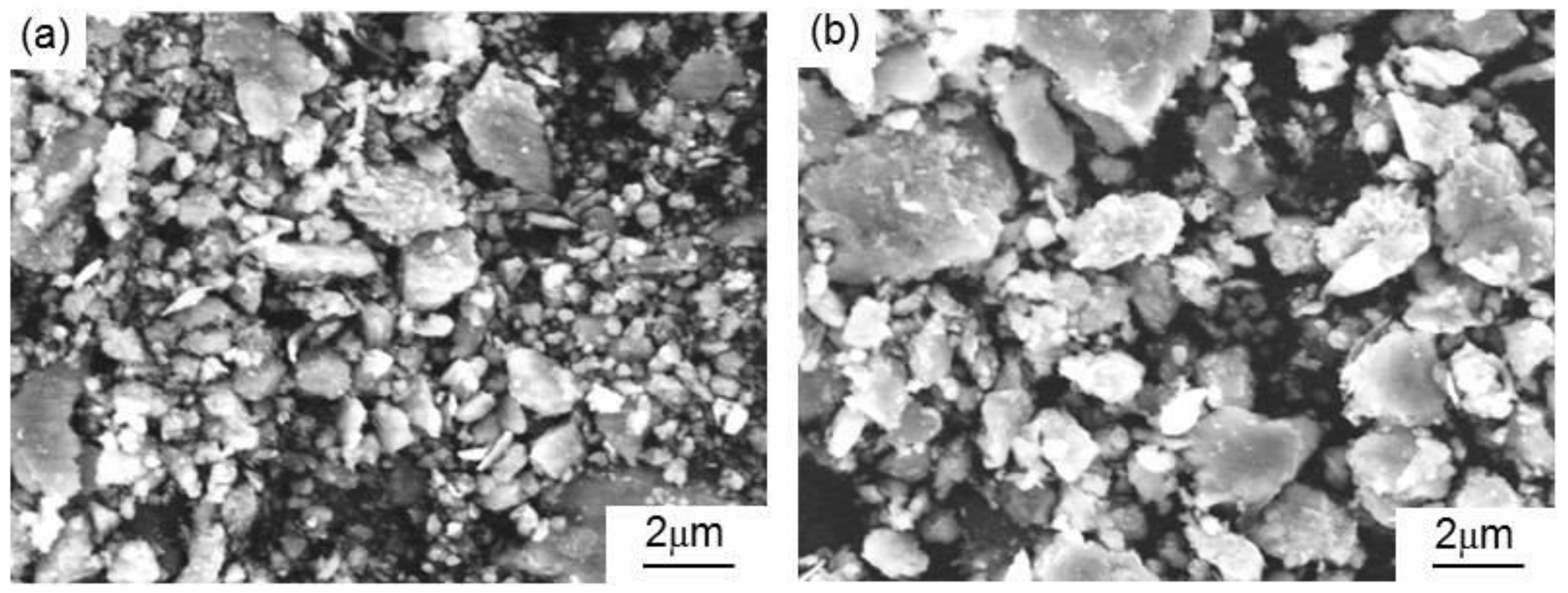
3.1. Microstructure Characterization
3.2. Mechanical Properties
3.2.1. Brinell Hardness
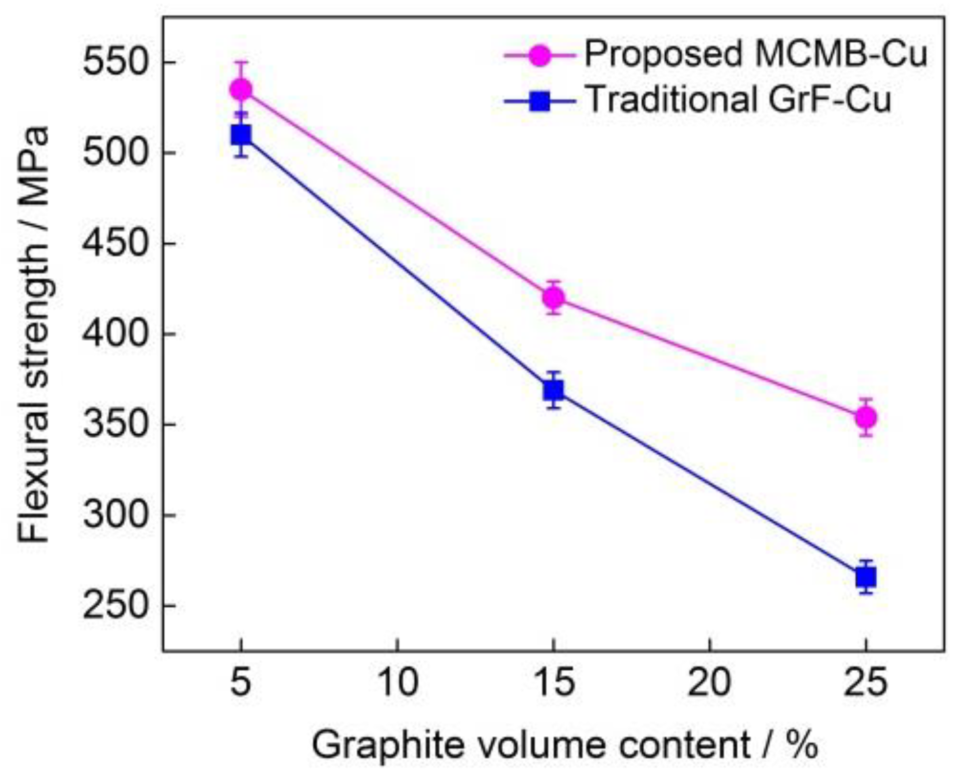
3.2.2. Flexural Strength
3.3. Tribological Properties
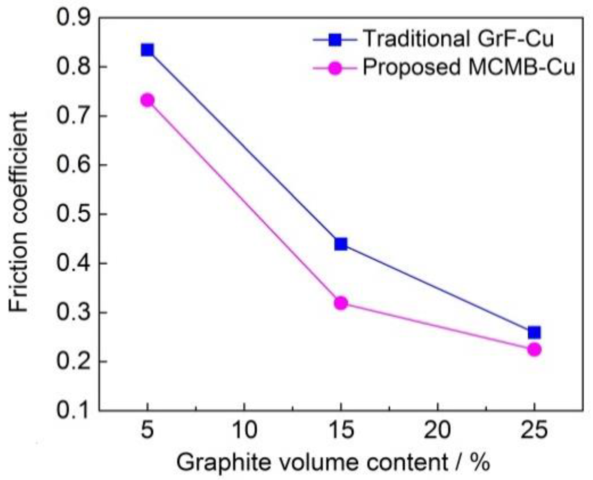
3.3.1. Friction Coefficient
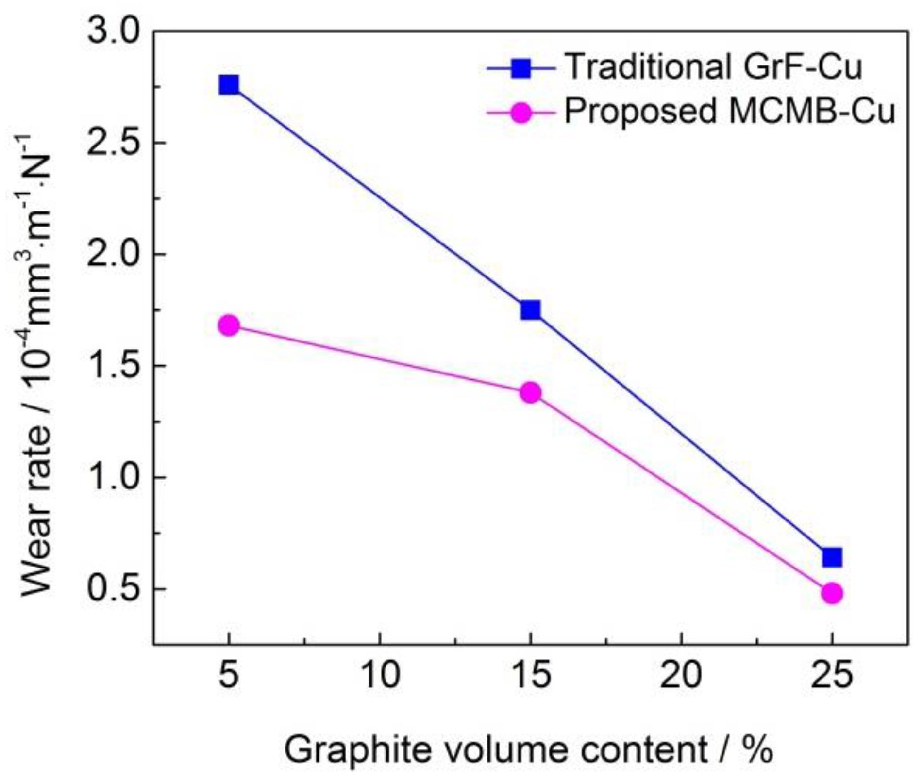
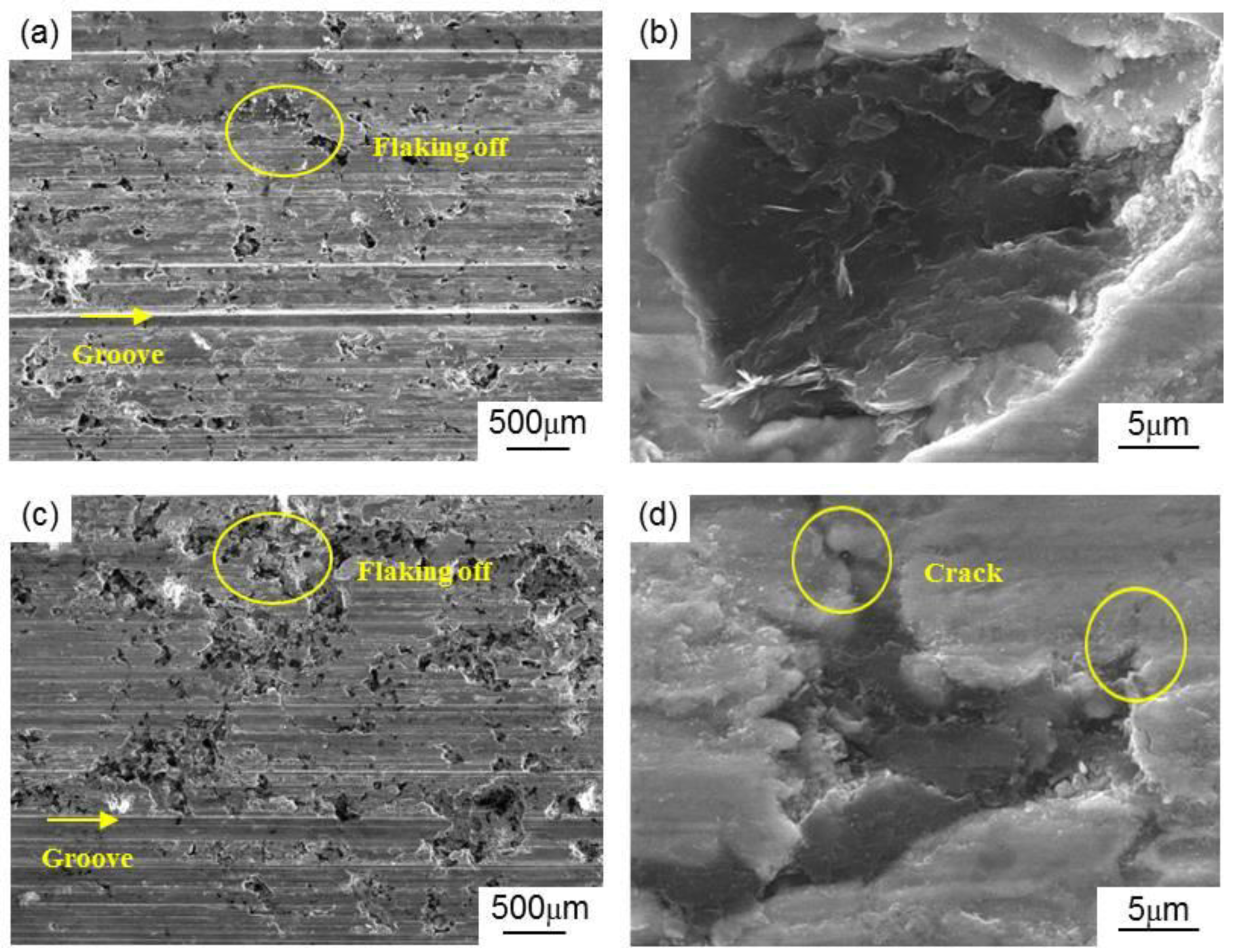
3.3.2. Wear Rate
4. Conclusions
Author Contributions
Funding
Conflicts of Interest
References
- Xiao, Y.L.; Yao, P.P.; Zhou, H.B.; Zhang, Z.Y.; Gong, T.M.; Zhao, L.; Zuo, X.T.; Deng, M.W.; Jin, Z.X. Friction and wear behavior of copper matrix composite for spacecraft rendezvous and docking under different conditions. Wear 2014, 320, 127–134. [Google Scholar] [CrossRef]
- Nayak, D.; Ray, N.; Sahoo, R.; Debata, M. Analysis of tribological performance of Cu hybrid composites reinforced with graphite and TiC using factorial techniques. Tribol. Trans. 2014, 57, 908–918. [Google Scholar] [CrossRef]
- Ram Prabhu, T.; Varma, V.K.; Vedantam, S. Tribological and mechanical behavior of multilayer Cu/SiC+ Gr hybrid composites for brake friction material applications. Wear 2014, 317, 201–212. [Google Scholar] [CrossRef]
- Chen, W.Y.; Yu, Y.; Cheng, J.; Wang, S.; Zhu, S.Y.; Liu, W.M.; Yang, J. Microstructure, mechanical properties and dry sliding wear behavior of Cu-Al2O3-graphite solid-lubricating coatings deposited by low-pressure cold spraying. J. Therm. Spray Technol. 2018, 27, 1652–1663. [Google Scholar] [CrossRef]
- Xiao, Y.L.; Zhang, Z.Y.; Yao, P.P.; Fan, K.Y.; Zhou, H.B.; Gong, T.M.; Zhao, L.; Deng, M.W. Mechanical and tribological behaviors of copper metal matrix composites for brake pads used in high-speed trains. Tribol. Int. 2018, 119, 585–592. [Google Scholar] [CrossRef]
- Zhan, Y.Z.; Zhan, G.D. Graphite and SiC hybrid particles reinforced copper composite and its tribological characteristic. J. Mater. Sci. Lett. 2003, 22, 1087–1089. [Google Scholar] [CrossRef]
- Ram Prabhu, T. Effects of solid lubricants, load, and sliding speed on the tribological behavior of silica reinforced composites using design of experiments. Mater. Des. 2015, 77, 149–160. [Google Scholar] [CrossRef]
- Chen, B.M.; Bi, Q.L.; Yang, J.; Xia, Y.Q.; Hao, J.C. Tribological properties of Cu-based composites and in situ synthesis of TiN/TiB2. Mater. Sci. Eng. A 2008, 491, 315–320. [Google Scholar] [CrossRef]
- Xu, Z.S.; Zhang, Q.X.; Huang, X.J.; Liu, R.; Zhai, W.Z.; Yang, K.; Zhu, Q.S. An approximate model for the migration of solid lubricant on metal matrix self-lubricating composites. Tribol. Int. 2016, 93, 104–114. [Google Scholar] [CrossRef]
- Rajkumar, K.; Aravindan, S. Tribological performance of microwave sintered copper-TiC-graphite hybrid composites. Tribol. Int. 2011, 44, 347–358. [Google Scholar] [CrossRef]
- Zhan, Y.Z.; Zhan, G.D. The role of graphite particles in the high-temperature wear of copper hybrid composites against steel. Tribol. Lett. 2006, 17, 91–98. [Google Scholar] [CrossRef]
- Wang, J.X.; Zhang, R.J.; Xu, J.; Wu, C.; Chen, P. Effect of the content of ball-milled expanded graphite on the bending and tribological properties of copper-graphite composites. Mater. Des. 2013, 47, 667–671. [Google Scholar] [CrossRef]
- Chen, B.M.; Bi, Q.L.; Yang, J.; Xia, Y.Q.; Hao, J.C. Tribological properties of solid lubricants (graphite, h-BN) for Cu-based P/M friction composites. Tribol. Int. 2008, 41, 1145–1152. [Google Scholar] [CrossRef]
- Shao, Z.; Sun, Y.; Liu, W.; Xu, J.; Wu, C.; Chen, P. Effects of multi-phase reinforcements on microstructures, mechanical and tribological properties of Cu/Ti3SiC2/C/BN/GNPs nanocomposites sintered by vacuum hot-pressing and hot isostatic pressing. Metals 2016, 6, 324. [Google Scholar] [CrossRef] [Green Version]
- Mochida, I.; Korai, Y.; Ku, C.H. Chemistry of synthesis, preparation and application of aromatic-derived mesophase pitch. Carbon 2000, 38, 305–328. [Google Scholar] [CrossRef]
- Brooks, J.D.; Taylor, G.H. The formation of graphitizing carbons from the liquid phase. Carbon 1965, 3, 185–186. [Google Scholar] [CrossRef]
- Norfolk, C.; Kaufmann, A.; Mukasyan, A.; Mukasyan, A.; Varma, A. Processing of mesocarbon microbeads to high-performance materials: Part III. High-temperature sintering and graphitization. Carbon 2006, 44, 301–306. [Google Scholar] [CrossRef]
- Boz, M.; Kurt, A. The effect of Al2O3 on the friction performance of automotive brake friction materials. Tribol. Int. 2007, 40, 1161–1169. [Google Scholar] [CrossRef]
- Jiang, X.S.; Liu, W.X.; Li, J.R.; Shao, Z.Y.; Zhu, D.G. Microstructures and mechanical properties of Cu/Ti3SiC2/C/MWCNTs composites prepared by vacuum hot-pressing sintering. J. Alloys Compd. 2015, 618, 700–706. [Google Scholar]
- Ram Prabhu, T.; Varma, V.K.; Vedantam, S. Effect of SiC volume fraction and size on dry sliding wear of Fe/SiC/graphite hybrid composites for high sliding speed applications. Wear 2014, 309, 1–10. [Google Scholar] [CrossRef]
- Fujimoto, H. A new estimation method for the degree of graphitization for random layer lattices. Carbon 2010, 48, 3446–3453. [Google Scholar] [CrossRef]
- Iwashita, N.; Park, C.R.; Fujimoto, H.; Shiraishi, M.; Inagaki, M. Specification for a standard procedure of X-ray diffraction measurements on carbon materials. Carbon 2004, 42, 701–714. [Google Scholar] [CrossRef]
- Zhang, X.J.; Dong, P.Y.; Zhang, B.G.; Tang, S.Y.; Yang, Z.R.; Chen, Y.; Yang, W.C. Preparation and characterization of reduced graphene oxide/copper composites incorporated with nano-SiO2 particles. J. Alloys Compd. 2016, 671, 465–472. [Google Scholar] [CrossRef]
- Zum Gahr, K.H. Abrasive wear of microstructures with internal notches. Strength Met. Alloys 1979, 1, 225–230. [Google Scholar]
- Archard, J.F. Contact and rubbing of flat surfaces. J. Appl. Phys. 1953, 24, 981. [Google Scholar] [CrossRef]
- Kováčik, J.; Emmer, Š.; Bielek, J. Effect of composition on friction coefficient of Cu-graphite composites. Wear 2008, 265, 417–421. [Google Scholar] [CrossRef]
- Meng, Q.; Wang, Z. Prediction of interfacial strength and failure mechanisms in particle-reinforced metal-matrix composites based on a micromechanical model. Eng. Fract. Mech. 2015, 142, 170–183. [Google Scholar] [CrossRef]
- Meng, Q.; Wang, Z. Creep damage models and their applications for crack growth analysis in pipes: A review. Eng. Fract. Mech. 2019, 205, 547–576. [Google Scholar] [CrossRef]
- Ferrer, C.; Pascual, M.; Busquets, D.; Rayón, E. Tribological study of Fe-Cu-Cr-graphite alloy and cast iron railway brake shoes by pin-on-disc technique. Wear 2010, 268, 784–789. [Google Scholar] [CrossRef]
- Mann, R.; Magnier, V.; Brunel, J.F.; Brunel, F.; Dufrénoy, P.; Henrion, M. Relation between mechanical behavior and microstructure of a sintered material for braking application. Wear 2017, 386, 1–16. [Google Scholar] [CrossRef]


| Samples | MCMB | GrF | Al2O3 | Cu | Fe | Al |
|---|---|---|---|---|---|---|
| MCMB-5 | 5.0 | 0 | 5.0 | 50.4 | 34.2 | 5.4 |
| MCMB-15 | 15.0 | 0 | 5.0 | 44.8 | 30.4 | 4.8 |
| MCMB-25 | 25.0 | 0 | 5.0 | 39.2 | 26.6 | 4.2 |
| GrF-5 | 0 | 5.0 | 5.0 | 50.4 | 34.2 | 5.4 |
| GrF-15 | 0 | 15.0 | 5.0 | 44.8 | 30.4 | 4.8 |
| GrF-25 | 0 | 25.0 | 5.0 | 39.2 | 26.6 | 4.2 |
| Samples | Theoretical Density (g/cm3) | Bulk Density (g/cm3) | Relative Density (%) | Porosity (%) |
|---|---|---|---|---|
| MCMB-5 | 7.62 | 7.43 | 97.51 | 2.49 |
| MCMB-15 | 7.03 | 6.95 | 98.72 | 1.28 |
| MCMB-25 | 6.45 | 6.34 | 98.29 | 1.71 |
| GrF-5 | 7.62 | 7.50 | 98.42 | 1.58 |
| GrF-15 | 7.03 | 6.90 | 98.15 | 1.85 |
| GrF-25 | 6.45 | 6.21 | 96.27 | 3.73 |
| Composition (S Marker) | Element | Weight Percent % | Atom Percent % |
|---|---|---|---|
| C K | 6.59 | 24.71 | |
| Fe K | 93.41 | 75.26 | |
| total | 100 | 100 | |
| Composition (F Marker) | C K | 0.01 | 0.05 |
| Fe K | 99.99 | 99.95 | |
| total | 100 | 100 |
© 2020 by the authors. Licensee MDPI, Basel, Switzerland. This article is an open access article distributed under the terms and conditions of the Creative Commons Attribution (CC BY) license (http://creativecommons.org/licenses/by/4.0/).
Share and Cite
Guo, H.-X.; Yang, J.-F. Fabrication and Tribological Properties of Mesocarbon Microbead–Cu Friction Composites. Materials 2020, 13, 463. https://doi.org/10.3390/ma13020463
Guo H-X, Yang J-F. Fabrication and Tribological Properties of Mesocarbon Microbead–Cu Friction Composites. Materials. 2020; 13(2):463. https://doi.org/10.3390/ma13020463
Chicago/Turabian StyleGuo, Hai-Xia, and Jian-Feng Yang. 2020. "Fabrication and Tribological Properties of Mesocarbon Microbead–Cu Friction Composites" Materials 13, no. 2: 463. https://doi.org/10.3390/ma13020463