1. Introduction
In order to meet the customer’s various needs, a flexible manufacturing system, which includes flexibility for small batch production [
1], is increasing. Incremental sheet metal forming is a suitable forming technology for the aforementioned types of flexible manufacturing systems [
2]. This corresponds to forming technology that produces the desired shape by increasing small deformations in contact with the tool and sheet.
Iseki et al. [
3] proposed single point incremental forming (SPIF). The incremental forming technology uses only a three-dimensional tool path and a simple forming tool on a CNC machine. Typical sheet metal forming requires the production of a die and punch. However, the incremental forming employs a round tool and tool path, as shown in
Figure 1a, instead of a die-set. Consequently, the formability exceeds that of a typical forming technology, and thus various products can be manufactured [
4].
However, shape errors occur during and after forming in incremental forming [
5]. During forming, bending deformation occurs in the sheet by the force of the tool pressing the sheet and the force of the blank holder holding the sheet [
6]. Furthermore, after forming, skirt spring-back occurs due to the elastic recovery of the sheet. It is impossible to produce the desired shape despite the aforementioned problems.
Figure 1b shows a schematic drawing of shape errors, such as the section deflection, spring-back, and height error in the formed shape.
There are many studies to increase formability and accuracy in SPIF. Duflou et al. [
7] employed a laser beam to heat locally where the tool contacts the material. Local heating resulted in reduced process forces, improved dimensional accuracy, and increased formability. Allwood et al. [
8] adopted the closed-loop feedback control in the single point incremental forming process. The tool path was modified with the iterative process. Bambach et al. [
5] increased the geometric accuracy by employing multi-stage forming. Malhotra et al. [
9] calculated the proper scallop height in a 3D spiral tool path to increase geometric accuracy and decrease forming time. Zhu et al. [
10] developed a 5-axis incremental forming tool and related tool paths to reduce the residual height of the product. Yang and Chen [
11] studied the twist phenomena in SPIF and proposed an alternate tool path to restrain twist deformation.
Matsubara et al. [
12] proposed two point incremental forming (TPIF). TPIF employs a fixture or die-set at the bottom of the sheet and the tool moves on the sheet with the designated tool path. Nguyen et al. [
13] employed a negative wooden die to manufacture a small automotive white-body. Silva and Martines [
14] studied the deformation mechanics of SPIF and TPIF through an analytic model and experiments. Panjwani et al. [
15] introduced a flexible bolt support technique with an array of bolts in the incremental forming process. Ou et al. [
16] studied process parameters of TPIF with a positive die-set to improve thickness uniformity for an irregular stepped part.
Meier et al. [
17] and Maidagan et al. [
18] proposed the concept of double side incremental forming (DSIF), in which two tools simultaneously form two sides of a sheet. DSIF employs two moving tools acting as a forming tool and a supporting tool to increase flexibility and geometric accuracy. Malhotra et al. [
19] and Moser et al. [
20] studied forming strategies in DSIF to increase formability and geometric accuracy. Praveen et al. [
21] compensated the tool paths in DSIF using an analytic model to enhance the geometric accuracy.
In this work, the two-stage SPIF process was developed to decrease shape error in SPIF. Jung et al. [
22,
23] proposed a new additional incremental forming process for after the conventional incremental forming process.
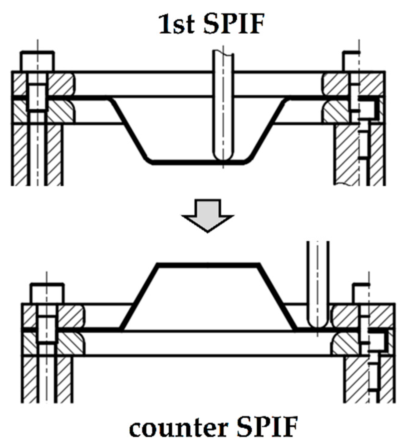
Figure 2 shows a schematic of an incremental forming process to decrease shape errors in SPIF. The forming process rotated the sheet 180° after general incremental forming. The sheet after the first incremental forming (1st SPIF) was rotated, and the tool created deformations to reduce shape error. However, they just showed the possibilities of the proposed process. The height of the manufactured product was different from the CAD data.
There have been many studies about the finite element analysis of the incremental forming process. Said et al. [
24] simulated ductile fracturing of the incremental forming process. Kim et al. [
25] studied the effects of the numerical simulation conditions, such as the contact condition and element types, on the simulation results. Guzmán et al. [
26] and Bouhamed et al. [
27] adopted Hill’s quadratic anisotropic non-associated flow rule with mixed isotropic nonlinear kinematic hardening to simulate the deformed geometry in the incremental forming process. Thickness distribution and plastic strains were predicted property with the finite element analysis. Still, the finite element simulation of SPIF was not sufficient to predict the deformed geometry after spring-back accurately [
28]. Another problem is the simulation time. The simulations of SPIF require more time than experiments. Consequently, experiments were conducted to find out the proper tool paths instead of the finite element analysis.
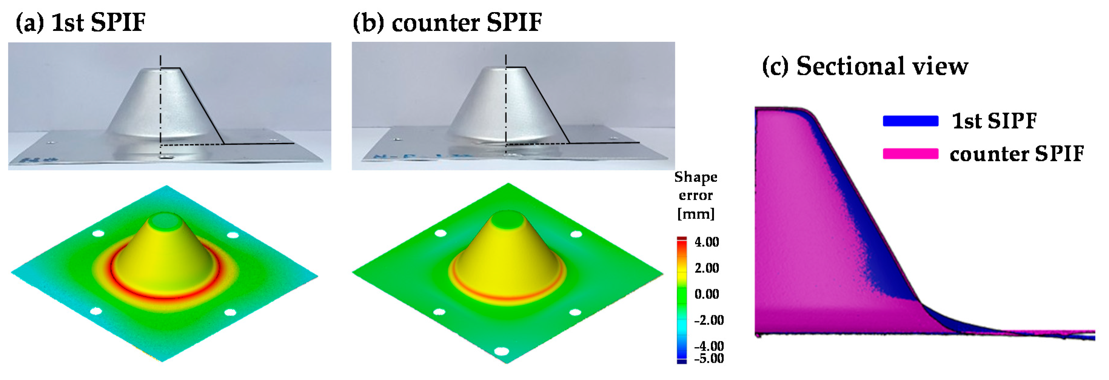
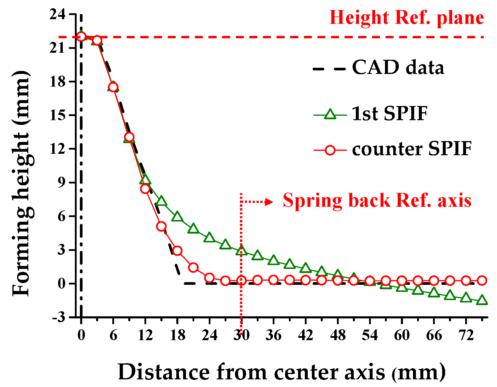
The first conventional incremental forming process was denoted as the single point incremental forming (1st SPIF). The additional forming process was denoted as the counter single point incremental forming (counter SPIF). In the study, we proposed a procedure to construct the tool path for counter SPIF to decrease shape error. The tool path in the counter SPIF process was modified by measuring the shape error after the 1st SPIF process. Using a simple optimization method, the tool path in counter SPIF for minimizing shape error was compensated. Additionally, the shape error along the direction, the skirt angle, and the height was corrected using the clover-shaped tool path in the counter SPIF. Experiments with the circular cup shape and the ship hull shape were performed to verify the proposed method.
3. Tool Path Design for the Counter SPIF
3.1. Definition of the Shape Error
Figure 4 is a schematic figure of the deformed geometry after the conventional SPIF. The reference geometry is the circular cup shape. The reference plane is the highest surface, which was minimally affected by the incremental forming. The forming height (
h) denotes the height from the reference plane to the top surface of the sheet. The final forming height (
H) denotes the forming height from the reference plane to the endpoint. The skirt spring-back (
θ) denotes the angle between the endpoint and initial contact point in the counter SPIF. The round (
R) denotes the arc between the slope and the material. The measurement reference point denotes the position of the initial contact point of the tool in the conventional incremental forming process. In this study, an ATOS Core optical 3D scanner with an error of 0.001 mm was used. Additionally, the sheets were scanned on a bed that could rotate 360°. The section profiles of the top surface based on the line connecting the center point of the sheet were compared.
3.2. Tool Path Modification to Increase the Geometric Accuracy
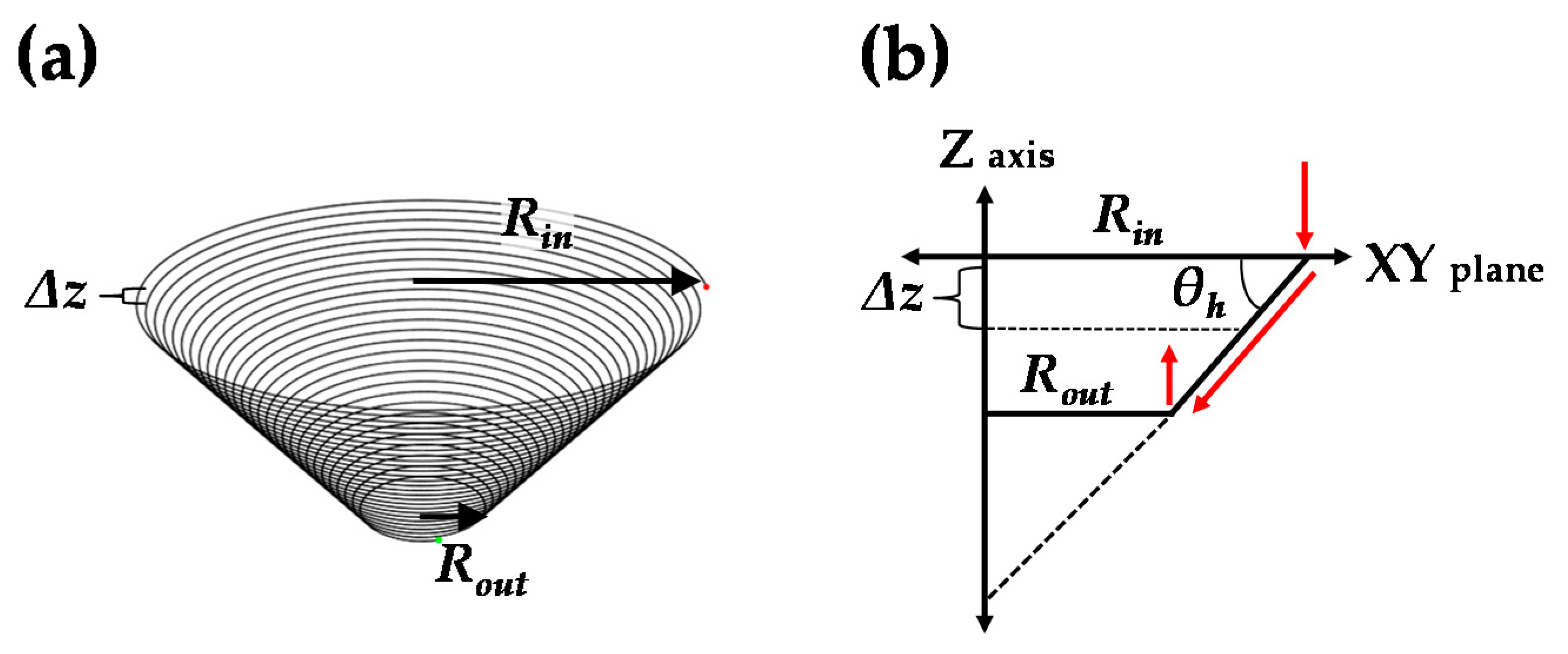
First, the tool path of the conventional incremental forming process must be described. The tool path of a circular cup shape is shown in
Figure 5. The tool path was controlled by parameters of the entry radius (
Rin), exit radius (
Rout), forming angle (
θh), and step-down size (Δ
z).
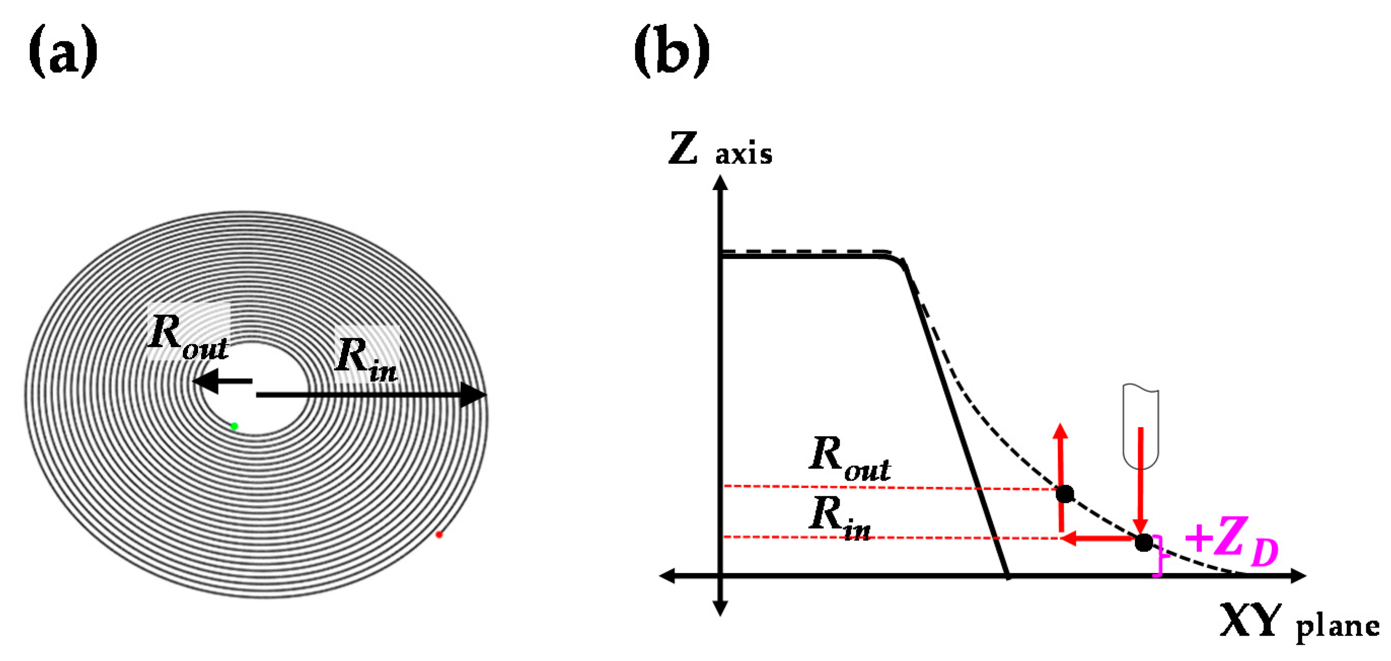
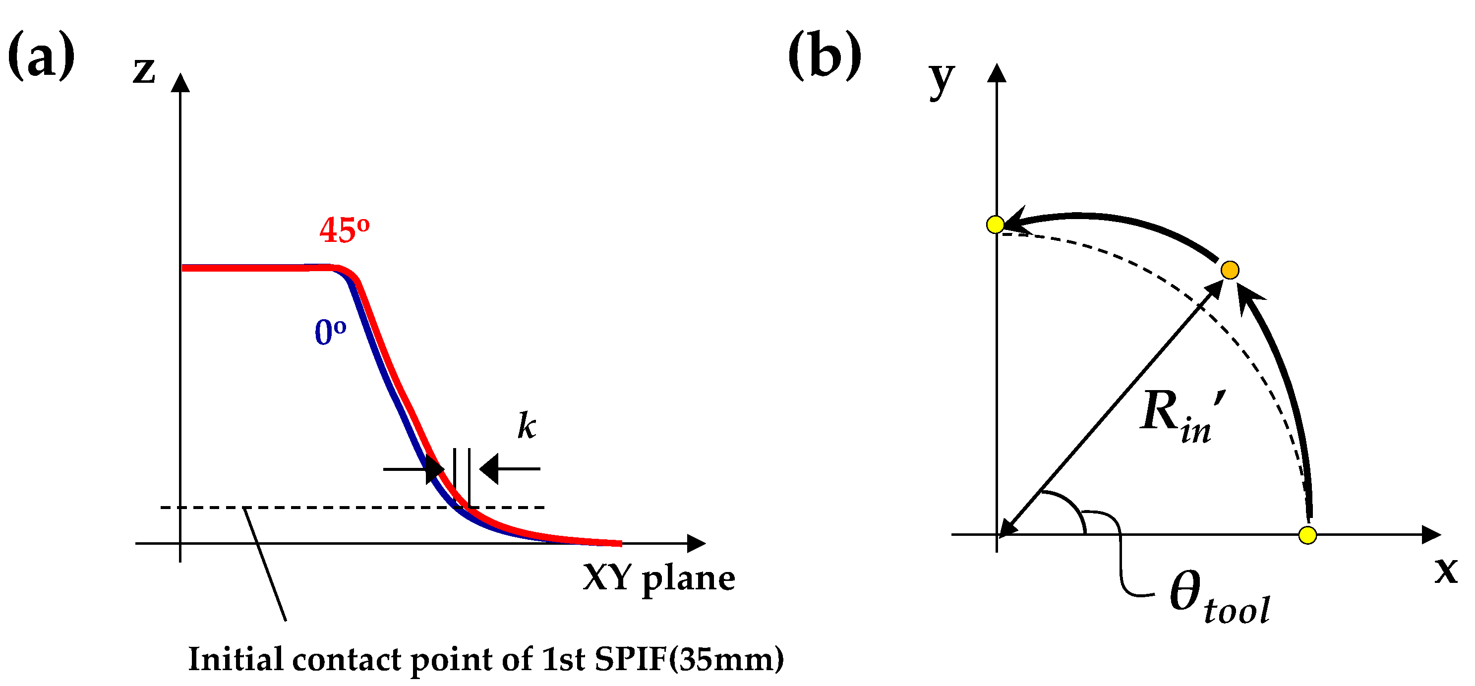
The tool path of counter SPIF was modified according to the shape error. The initial tool path of counter SPIF was disk shaped, as shown in
Figure 6. The tool path can decrease the shape error though additional forming of the section deflection region of the circular cup shape. It gives bending deformation in the opposite direction. The tool path is controlled by parameters of the entry radius (
Rin), exit radius (
Rout), entry depth of tool (
ZD), and step-down size (Δ
z). The entry depth of the tool (
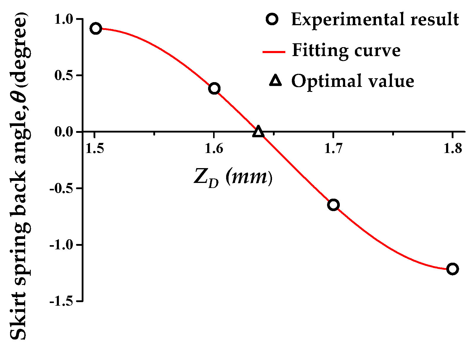
ZD) is the main process parameter for controlling the bending deformation in the opposite direction. The
ZD is defined with reference to the XY plane. The XY plane denotes the bottom when the sheet is rotated 180° after forming a circular cup shape.
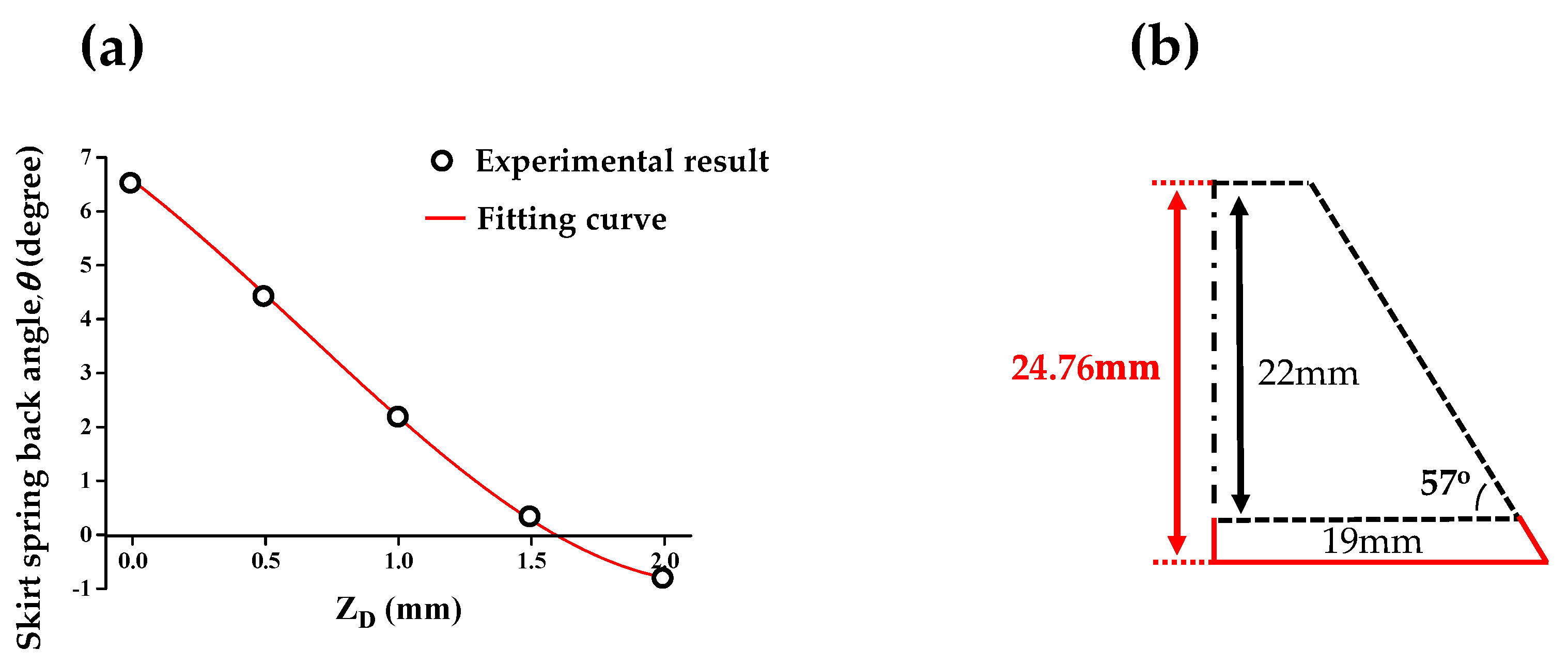
However, the disk-shaped tool path in the counter SPIF results in other shape errors, such as height differences and shape errors according to the angle of the sheet. In the previous work [
23], the skirt angle of the product was minimized in counter SPIF by controlling the value of
ZD. However, the height of the incremental formed product was reduced, because the skirt region of the product was deformed in the counter SPIF.
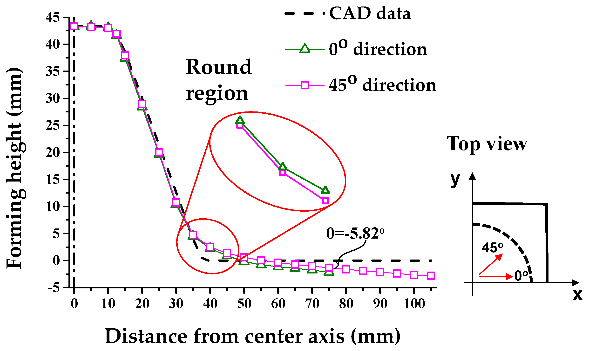
Additionally, the blank in this work was rectangular. The distances between the first contact area of the tool and the blank are different. As a result, the deformed shape of the product is different along one direction. The clover-shaped tool path was adopted to reduce shape error along that direction.
3.3. Compensation Process of the Tool Path for the Counter SPIF
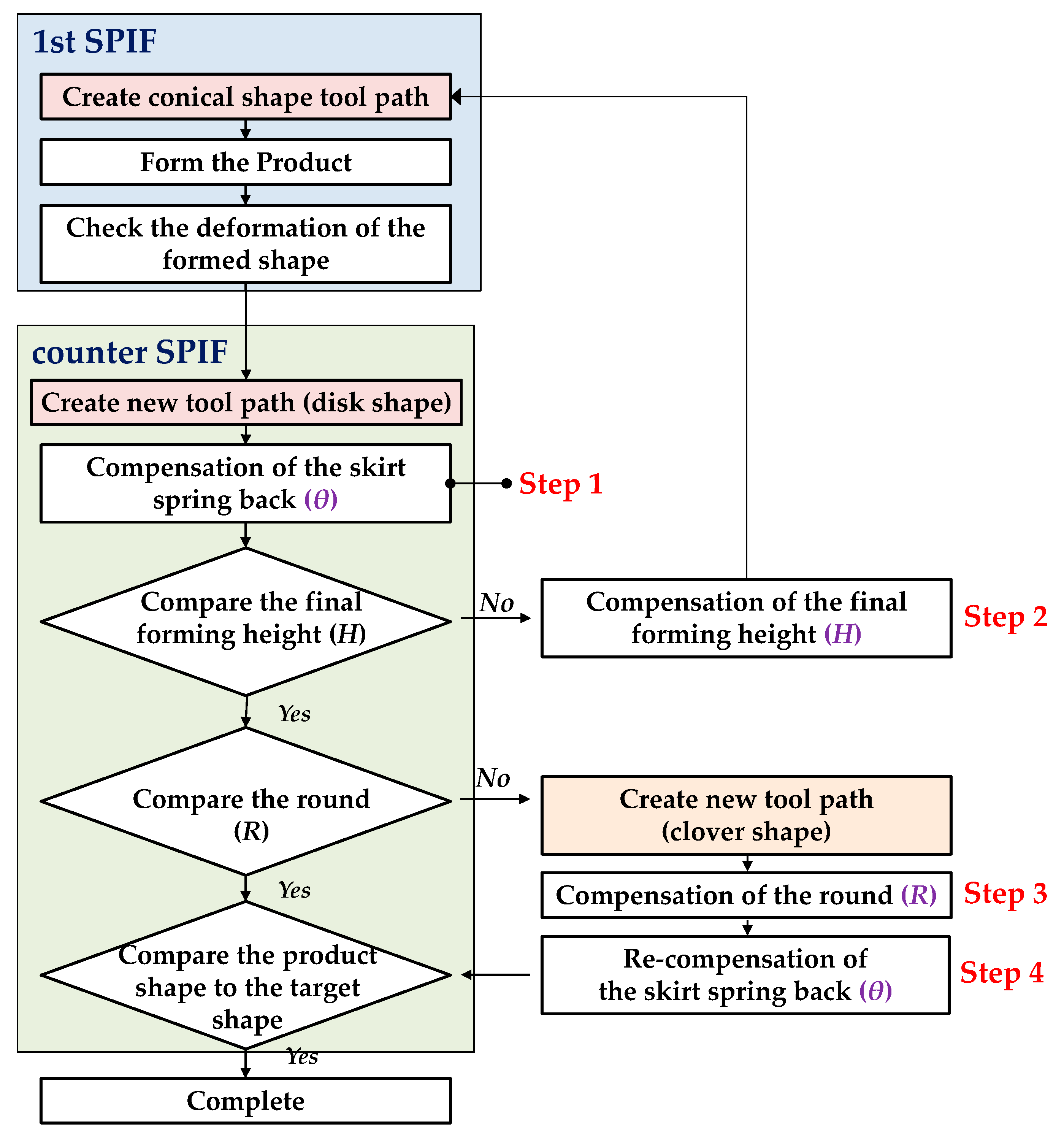
Figure 7 shows a flow chart to generate the tool path for the two-stage forming process. In the 1st SPIF, the tool path of the first trial was the same as the tool path in the conventional SPIF [
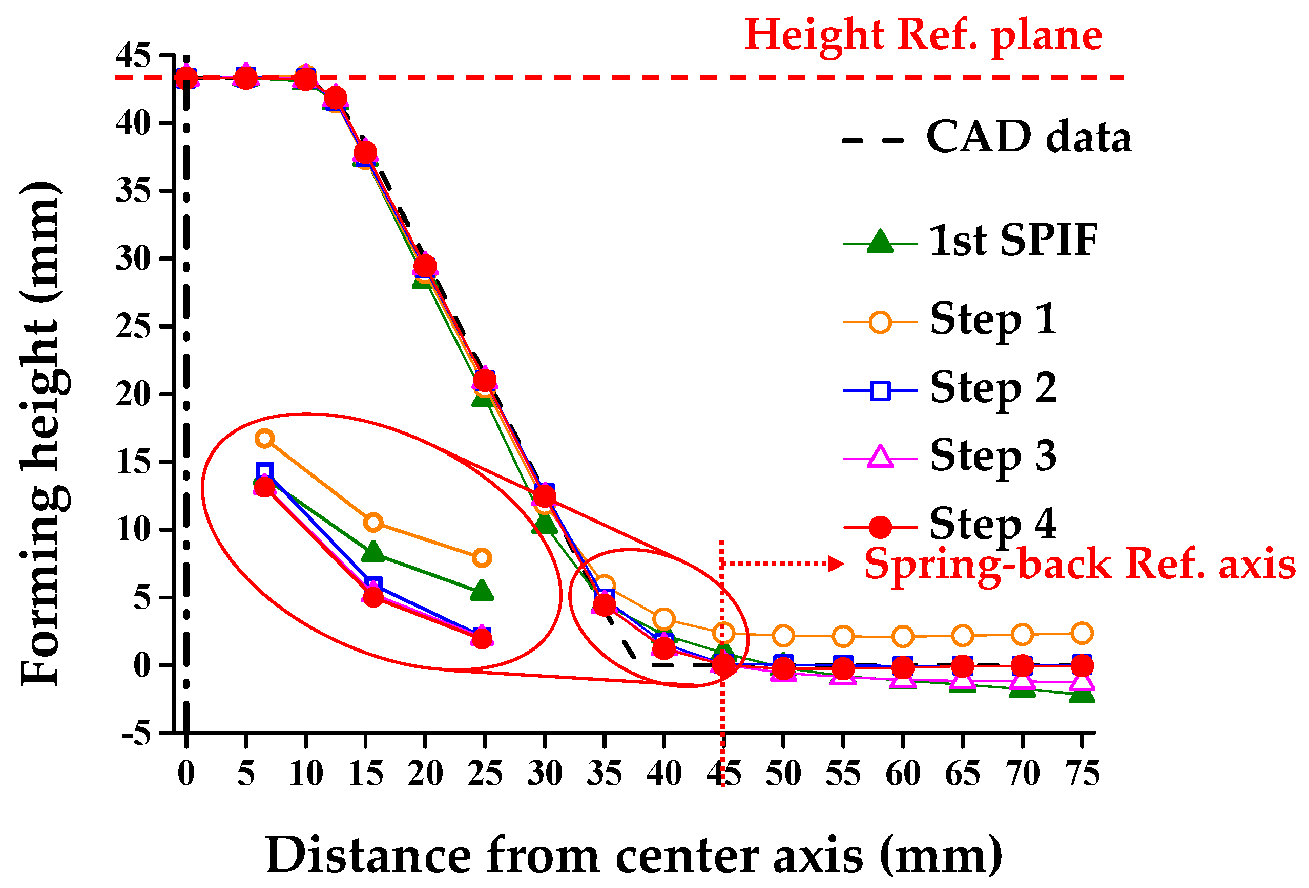
23]. In the counter SPIF, a four-step compensation method was used to decrease the shape error.
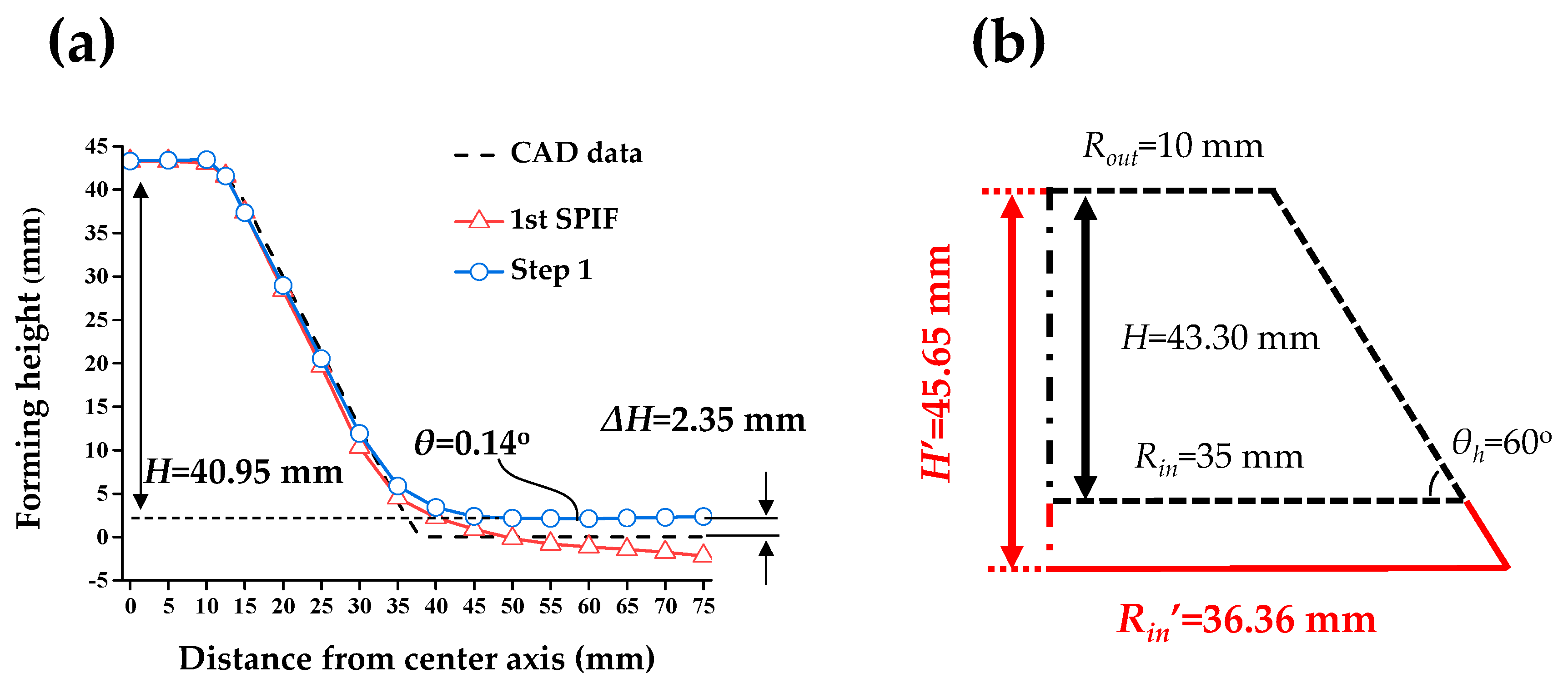
In step 1, θ was compensated. ZD in the counter SPIF was determined through the simple optimization method. In step 2, H was compensated. Due to the unbending in the counter SPIF, the final forming height of the product decreased. In order to compensate for the final forming height of the circular cup, the tool path in the 1st SPIF was modified. In step 3, R was compensated using the changed tool path. When the cross-section showed different results, the tool path of the counter SPIF was modified with the clover shape. In step 4, θ was recompensated from the changed tool path, because the modified tool path in step 3 resulted in different sectional geometry. Through the simple optimization methods, the optimized ZD in the counter SPIF was determined.
When the difference in geometry by direction was not significant, the optimization could be finished after step 2.
3.4. Experimental Conditions and Measurement Method
In the experiment, incremental forming was performed to decrease the shape error of the circular cup shape. To proceed with the experiment, a sequential forming process was performed.
Table 1 lists the initial experimental conditions of the 1st and counter SPIF.
The Δz in the 1st SPIF was 0.3 mm. Δz affects the forming time of the material and surface quality. Therefore, values were selected that would not cause a shallow pattern on the surface of the shape. The Δz in the counter SPIF was zero. That means that the tool moves along the XY plane when the tool contacts the sheet.
The Rout in the counter SPIF was 39 mm because of the diameter of the tool that was considered in the Rin of the 1st SPIF process. The Rout in the counter SPIF was larger than the Rin in the 1st SPIF.
With the process variables in
Table 1, it took nearly 7 min for the 1st SPIF process, and it took nearly 4 min for the counter SPIF.


