1. Introduction
Laser powder bed fusion (LPBF) is an additive manufacturing technology in which a laser melts successive powder layers in order to build the final part [
1]. Some of the LPBF process parameters are laser power (
P), hatch distance (
h), laser scan speed (
v), layer thickness (
t), baseplate preheating temperature and laser scan strategy (ϴ). The latter refers to the rotation of successive layers during the manufacturing process. Combining some of the process parameters, a key factor for LPBF technology known as energy density can be calculated, as shown in Equation (1). This factor indicates the energy provided to the material during manufacturing process [
2]:
Compared with conventional manufacturing processes (cast and wrought), LPBF technology offers some advantages, such as design freedom, reduced weight of parts, processing of complex parts, manufacturing of near-net-shape components and reduction of waste material [
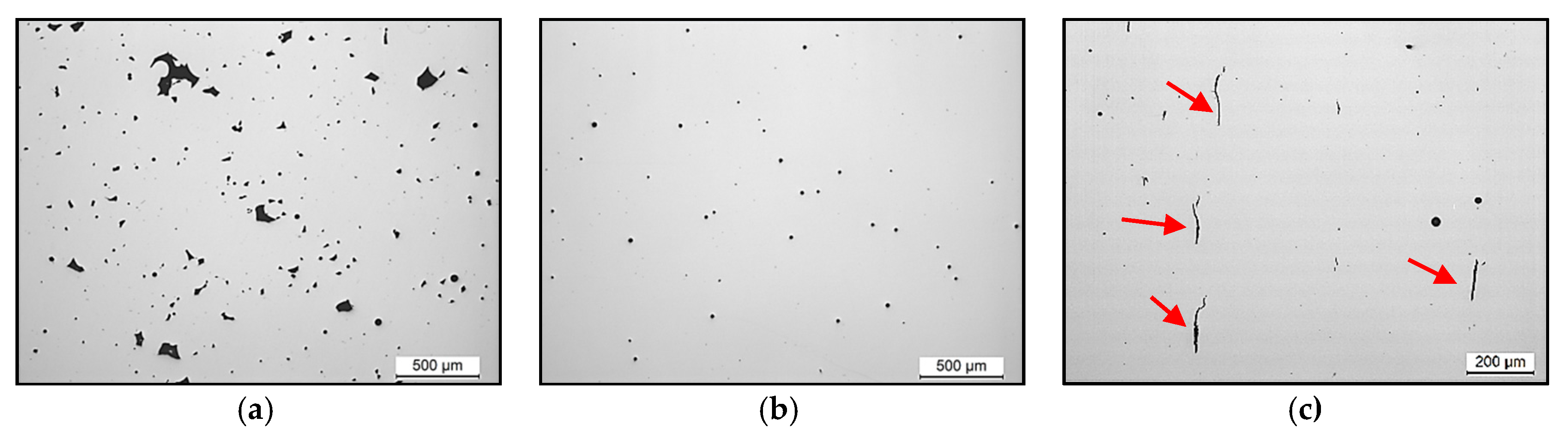
3]. Despite these advantages, the presence of defects such as pores and cracks in the manufactured final parts is a drawback for the implementation of this technology in the industry [
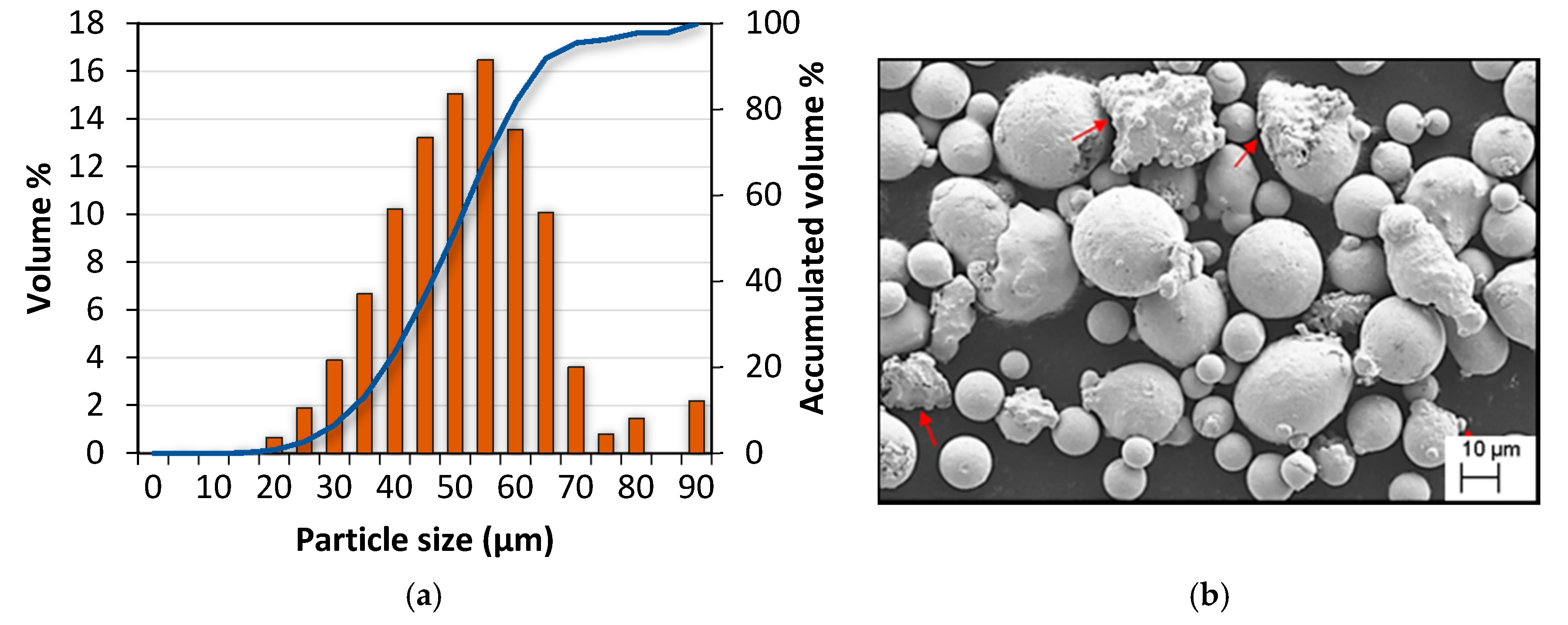
4]. In particular, the existence of porosity is attributed to different mechanisms: insufficient energy density, porosity in raw material, excessive energy density or large spatter particles [
5]. Pores formed by an insufficient energy density usually have irregular morphology due to the insufficient melting of the powder particles; nevertheless, porosity formed by the other mechanisms usually presents as spherical. For instance, powder particles’ inner porosity may be entrapped in the manufactured final parts due to the rapid solidification during LPBF process. Additionally, when the applied energy density is too high, the melt pool becomes unstable, inducing the formation of spherical pores at the bottom of the melt pool which are known as keyhole defects [
2].
There is a wide range of materials processable by LPBF technology, including aluminum (Al) alloys [
6,
7,
8], titanium (Ti) alloys [
9], stainless steels [
10,
11], cobalt (Co) alloys [
12], cupper (Cu) alloys [
13] and nickel (Ni) alloys [
14,
15]. Among the nickel (Ni)-based superalloys, Inconel 738LC (IN738LC) is of huge interest for components of the hottest section of land-based and aeronautic gas turbine engines because of its corrosion resistance and creep properties at high temperatures [
16]. The microstructure of the superalloy consists of a face centered cubic (FCC) matrix strengthened by the precipitation of the ordered second phase γ’ which has a nominal composition of Ni
3(Al, Ti) [
17]. The corrosion resistance of the alloy is achieved by the formation of the Cr
2O
3 protective layer at the surface, whereas the outstanding mechanical properties at high temperatures are obtained by the precipitation of the γ’ phase.
Nevertheless, IN738LC alloy is not considered processable by LPBF technology because of its high susceptibility to cracking during manufacturing process. In the literature, the cracking susceptibility of IN738LC is explained by three main mechanisms: liquation cracking, solidification cracking and strain age cracking [
18,
19]. Liquation cracking occurs when the material is heated just below the liquidus temperature where some low melting point components—carbides, γ/γ’ eutectic, borides, etc.—could suffer partial or total melting. In the case of solidification cracking, it occurs at the final stages of solidification when the liquid fraction present in the material is around 6–10% [
20]. This liquid is enriched in some elements, such as zirconium (Zr) and boron (B), which decrease the solidification temperature of the alloy known as the solidus. Actually, the remaining liquid fraction accumulates in the intergranular zones, causing stress during its solidification, which acts as an initial point of cracking. While liquation and solidification cracking are liquid state mechanisms, strain age cracking is solid state mechanism which occurs during the precipitation of the γ’ phase. As the mismatch between Ni matrix and γ’ precipitates is below 1%, precipitation of the second phase occurs extremely rapidly, involving large amount of stress which could cause the separation of grain boundaries. This type of cracking tends to take place in Ni alloys with Al and Ti amounts higher than 4.5% (wt%) [
21].
Some authors have focused on eliminating the cracking phenomenon in Ni superalloys using different approaches. Rickenbacher et al. [
17] reduced crack density in the IN738LC superalloy through the optimization of LPBF process parameters. However, in order to obtain manufactured parts without cracks, they conducted HIP (hot isostatic pressing) as a post-processing step. Xu et al. [
18] asserted that using a sufficiently high preheating temperature, it is possible to decrease the alloy’s thermal range and to change the microstructure from columnar to equiaxial grains. This microstructural change implies a more homogeneous distribution of the liquid along grains, reducing or even eliminating the formation of cracks. In fact, they manufactured crack-free IN738LC parts by applying a preheating temperature of 1050 °C. Cloots et al. [
19] suggested that the formation of cracks in the IN738LC superalloy occurs by solidification cracking mechanism due to the presence of a thin liquid film along the investigated cracks. They confirmed by atom probe tomography technique that the liquid film along the cracks was rich in Zr and B elements. They concluded that in order to eliminate cracking, it would be necessary to minimize as much as possible the content of B and remove Zr from the alloy totally. Finally, Carter et al. [
22] suggested that by controlling scan strategy of manufactured samples, it was possible to significantly reduce cracking density. Actually, they studied island and simple scan strategies and determined that there were differences in the crack density values of the samples manufactured with each one of the strategies.
Due to the formation of defects in IN738LC parts, it is challenging trying to optimize process parameters. Furthermore, taking into account the manufacturing process variables and all their possible combinations, it would be unaffordable to find the optimum process parameters by means of trial and error method. For this reason, Perevoshchikova et al. [
23] used Doehlert’s design to optimize laser power, laser scan speed and hatch distance process parameters to manufacture samples with minimum porosity.
In this work, the authors propose the application of the response surface method (RSM) to optimize laser power, hatch distance, scan speed and scan strategy process parameters with a reduced number of trials. RSM consists of a design of experiments (DoE), polynomial model fitting and optimization with a combination of desirabilities and the steepest ascent method. The response surface method has been tested in several fields over the decades; however, the method does not ensure the expected results, so experimental verification is needed. The potential problems of RSM are related to the modeling error that could be induced by the measurement challenges. In the case of additive manufacturing, another problem could be caused by the sample’s position on the platform. In addition, one of the limitations of RSM may be the number of inputs, because when inputs are increased the number of samples for building the models is also exponentially increased. It may be important to point out that without previous information about the material, it will be necessary to build more than one model to set the appropriate process parameter range.
In the field of additive manufacturing, several researchers have used RSM for process parameter optimization. Wang et al. [
24] investigated the influences of some LPBF process parameters on the microstructure and mechanical properties of manufactured samples by RSM. They concluded that it was possible to increase the mechanical properties by the optimization of process parameters through applying RSM. In addition, Deng et al. [
25] manufactured 316L stainless steel samples with high density and low roughness using RSM for the process optimization. Terner et al. [
26] optimized the laser power and scanning speed processing parameters by using RSM to manufacture Co-CrMo samples with a residual porosity and an increase in the hardness of the material. In this study, the optimization was carried out to obtain samples with minimum porosity and no cracks. The method followed minimizes manufacturing time, material waste, post processing tasks and evaluation time.
4. Conclusions
This study investigated the use of models to obtain components fabricated by LPBF technology free of pores and cracks. Firstly, a widely used method, known as the response surface method, was successfully applied with the objective of reducing the number of experiments and selecting the process parameters for IN738LC alloy. In particular, the optimized LPBF process parameters were laser scan speed, laser power, hatch distance and scan strategy.
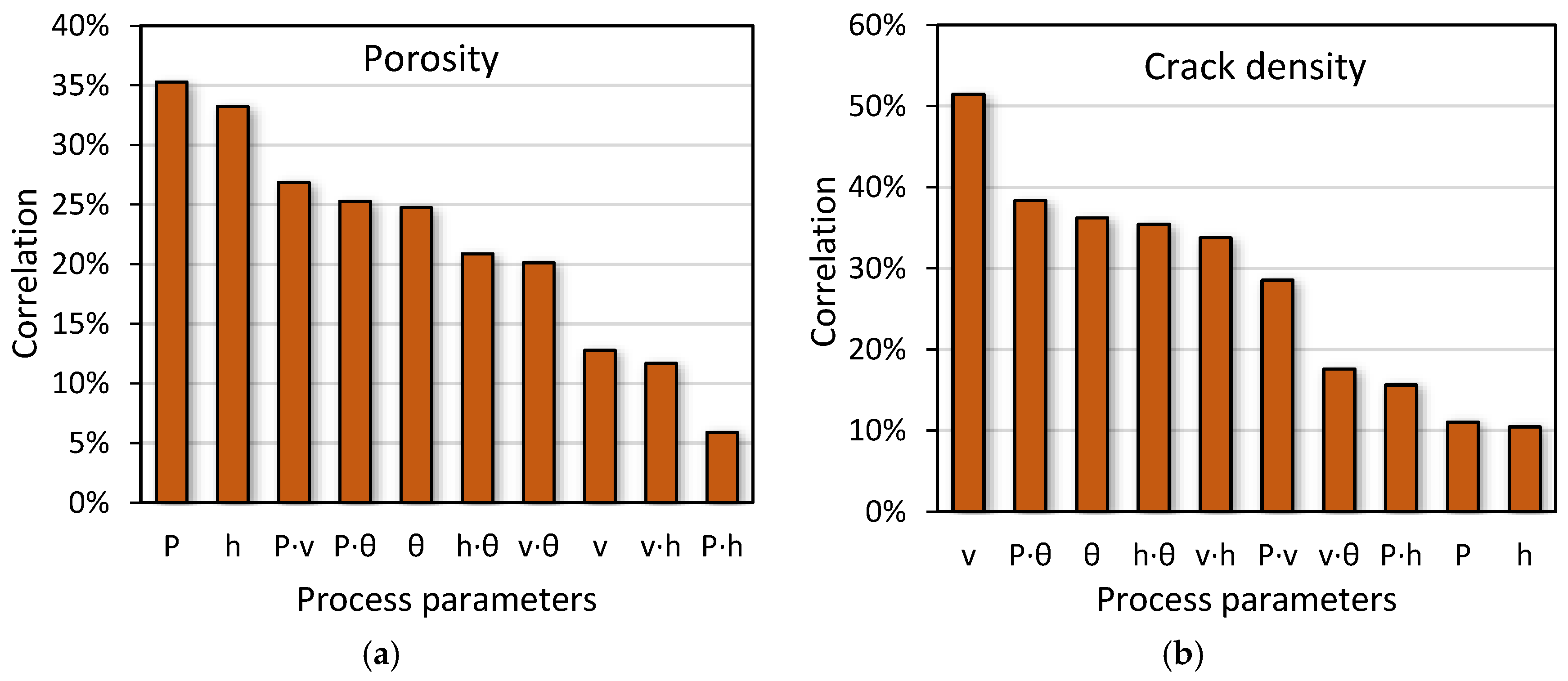
Secondly, it was possible to determine the influence of each process parameter on the formation of pores and cracks by correlation analysis. It was concluded that laser power and hatch space were the most influential factors in terms of pore formation. However, with respect to crack development, scan speed is the process parameter with the highest impact due to the fact that it may alter the material’s volume in the critical temperature range.
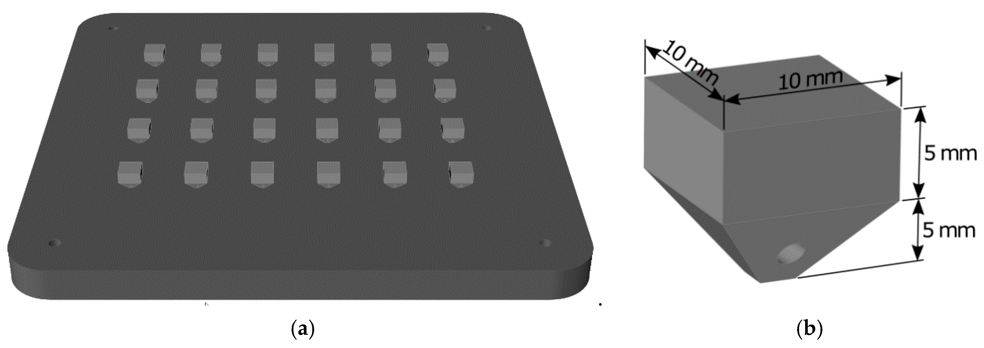
Finally, a design of experiments with 24 samples was defined. However, the results of just 20 samples were used to build the models, because samples with lack-of-fusion defect were dismissed. The process parameters determined by the model were used for the manufacturing of IN738LC superalloy by LPBF technology. Using the selected parameters, five samples were manufactured to experimentally validate the proposed method. After analyzing these samples, we verified the possibility of manufacturing samples with reduced porosity and no cracks.
Therefore, in the present work, it was demonstrated that despite the high cracking susceptibility of IN738LC superalloy, it is possible to manufacture samples through LPBF technology without cracks using the suitable process parameters obtained by RSM.


