Article

Coupled Preparation of Ferronickel and Cementitious Material from Laterite Nickel Ores

1
School of Metallurgical Engineering, Xi’an University of Architecture and Technology, Xi’an 710055, China
2
College of Materials Science and Engineering, Chongqing University, Chongqing 400044, China
*
Authors to whom correspondence should be addressed.
Materials 2020, 13(21), 4992; https://doi.org/10.3390/ma13214992
Submission received: 24 September 2020 / Revised: 24 October 2020 / Accepted: 30 October 2020 / Published: 5 November 2020

Abstract

:
Nickel slags can be produced through ferronickel preparation by the pyrometallurgical processing of laterite nickel ores; however, such techniques are underutilized at present, and serious environmental problems arise from the stockpiling of such nickel ores. In this study, a modification to the process of ferronickel preparation by the direct reduction of carbon bases in laterite nickel ores is proposed. The gangue from the ore is used as a raw material to prepare a cementitious material, with the main components of tricalcium silicate and tricalcium aluminate. By using FactSage software, thermodynamic calculations are performed to analyze the reduction of nickel and iron and the effect of reduction on the formation of tricalcium silicate and tricalcium aluminate. The feasibility of a coupled process to prepare ferronickel and cementitious materials by the direct reduction of laterite nickel ore and gangue calcination, respectively, is discussed under varying thermodynamic conditions. Different warming strategies are applied to experimentally verify the coupled reactions. The coupled preparation of ferronickel and cementitious materials with calcium silicate and calcium aluminate as the main phases in the same experimental process is realized.

1. Introduction

Nickel (Ni) is a transition element that exhibits a mixture of ferrous and nonferrous metal properties, and is used in many industries, for example for making stainless steel, superalloy, non-ferrous alloy, superalloy, coin, and batteries [1,2,3,4,5]. World nickel reserves are abundant [6]. Identified land-based resources averaging 1% nickel or greater contain at least 130 million tons of nickel, with about 60% in laterites and 40% in sulfide deposits. In 2019, nickel resources are divided into two types of ores: sulfide and laterite, of which sulfide ore accounts for about 30% and laterite nickel ore accounts for the rest [7,8,9]. In China, about 70% of nickel reserves are concentrated in Gansu Province, next to Canada’s Sadbury nickel, Asia rank the first and world rank the second, followed by Xinjiang, Yunnan, Jilin, and other places [10,11,12]. Before 2000, because of available upgrading methods, availability of high-grade ore, and low energy consumption in the extraction process, nickel was mainly produced from sulfide (60%), while laterite needed comprehensive treatment to extract nickel metal, resulting in a higher processing cost of laterite than nickel sulfide [13,14,15]. In recent years, with the rapid development of our national economy, the consumption of nickel is increasing day by day. At the same time, the total amount and grade of nickel sulfide ore resources shows a downward trend, and laterite is becoming increasingly important in the future. Therefore, pursuers begin to improve the nickel recovery technology of laterite nickel ore [16,17]. Laterite nickel ore has low exploration cost, mature technology, and broad development prospects. Therefore, nickel oxide mining is listed as a key project in China’s “medium and long term scientific development and regulation of non-ferrous metal industry (2006–2020)” (draft for comments) [18,19].
The nickel content of laterite ores is very low, and special treatments are needed to improve the nickel content of these ores, such as physical separation techniques, but the complexity of laterite nickels makes it difficult to achieve any significant breakthroughs [20,21,22,23,24,25]. Thermal modification of laterite ore by carbonization, dehydration, and reduction technologies has been shown to significantly improve nickel extraction in the acid leaching stage [26,27,28,29,30,31,32,33]. Pyrometallurgy is the main process route for nickel extraction from saprolite ore, and there are two commonly used laterite nickel smelting methods [34,35]. One is the rotary kiln dry-electric furnace reductive smelting. The laterite nickel ore is placed in the rotary kiln for drying intervention reduction at a temperature of 650–800 °C, and then placed in the reducing furnace at 1550–1600 °C for smelting and sorting to obtain coarse nickel iron. Nickel–iron alloys containing more than 25% nickel can be produced after further refining [36]. The second method is rotary kiln direct reduction. After drying, crushing, and sieving, the raw ore is mixed with lime and pulverized coal in proportion to the pellet. Drying and high temperature reduction produce spongy nickel–iron alloys and slag mixtures. After cooling, grinding, screening, and magnetic separation, the coarse nickel–iron particles were obtained. However, there are some problems in laterite nickel mining technology. In the process of rotary kiln drying-furnace reduction smelting, the melting temperature is high, the power consumption is large, the overall energy consumption is large, the slag production is large, the direct use failure is serious. Due to the direct reduction of rotary kiln, tailings yield is large and slag cannot be directly used, which increases the cost of subsequent treatment of nickel slag [37,38,39,40,41,42,43,44,45]. However, in the process of fire smelting of nickel–iron from laterite, the gangue components in the raw ore are comprehensively treated and applied to high value-added materials, so as to realize the green metallurgical utilization of laterite nickel, which has the characteristics of low cost, high added value, and short flowing time. There are great similarities between technology and equipment in traditional rotary kiln production of direct reducing iron and cement clinker production. First of all, the main equipment is the same rotary kiln, and the raw materials for the production of cement clinker are similar to the gangue composition in iron ore. Secondly, their main production processes are the same. All raw materials must be processed by the process of abrasive mixing—roasting—abrasive, and the roasting temperature is relatively close. The difference is that in the production process of direct reduced iron, it is necessary to separate the direct reduced iron from the gangue components after grinding by means of magnetic separation, while the purpose of cement clinker abrasive is to control the size of cementing materials. In the traditional direct reduced iron production process, gangue formation consumes a lot of energy in each process, but it cannot form high value-added products in the end. Instead, it is treated as solid waste.
Due to the correlation between the two production processes, we proposed the idea of coupling the process of preparing direct reduced iron with the process of preparing cementitious materials. The purpose of the experiment is to design a reaction coupling process. In the process of preparing direct reduced iron or nickel–iron alloy, it can also make the gangue component in the ore react with the CaO flux to produce the cementitious material. In a material flow and energy flow process, two different valuable products of nickel–iron alloy and cementitious material can be obtained without producing solid waste. Compared with the traditional process, the new process has the characteristics of high energy efficiency, high resource efficiency, and no solid waste. In this study, while preparing nickel iron from carbon base of laterite nickel ore by direct reduction, the gelling materials with silicate tricalcium silicate (C3S) and aluminate tricalcium (C3A) as main components were prepared from coal gangue. The coupling of these two reaction processes was investigated experimentally.

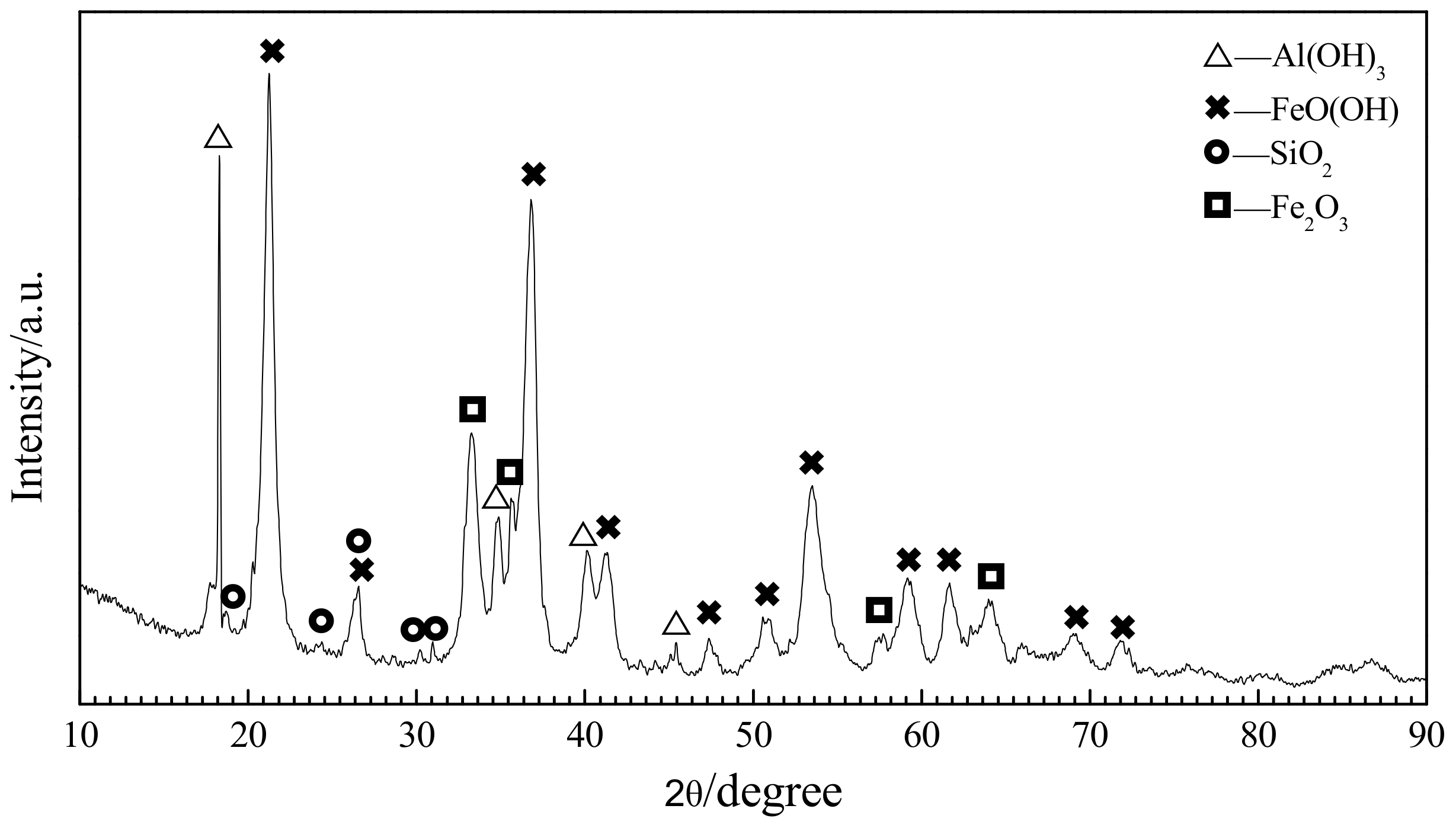
2. Material Analysis and Burdening

In the experiment, X-ray diffraction (XRD) analysis and fluorescence spectroscopy chemical component analysis were performed on the raw laterite nickel ore (Jinchuan Group Ltd., South Halmahera, Indonesia). The X-ray diffractometer used for detection is the Empyrean type with the scanning rate of 8°/min from PANalytical B.V (Almelo, Netherlands). The XRD analysis result from the laterite nickel ore is shown in Figure 1, and the chemical components determined through fluorescence spectroscopy are listed in Table 1.
The figure shows that the main phases of the laterite nickel ore are FeO(OH) (Goethite), Al(OH)3 (Gibbsite), and Fe2O3. The XRD peaks for the SiO2 phase are comparatively lower, and those for other minerals with calcium, magnesium, and nickel are not obvious. The laterite nickel ore thus has FeO(OH), Al(OH)3, and Fe2O3 as the main components.
According to XRD analysis and fluorescence spectroscopy, in the laterite nickel ore, FeO(OH) and Fe2O3 are the main phases. Among them, the content of Fe2O3 reaches 46.26%, the content of SiO2 is 3.30%, and the content of Al(OH)3 is equivalent to Al2O3, which accounts for 8.77% of the total mass, while the content of Ca, Mg, Ni, and other elements is less. Based on these characteristics of phase composition, through thermodynamic analysis and calculation, the process coupling for the reduction of nickel and iron and the formation of C3S, C3A, and other cementitious materials via the reaction of CaO with SiO2 or Al2O3 is calculated. Other elements with lower contents are not considered in the thermodynamic analysis.
Based on the above analysis, the mix ratio of reactants in the raw material is calculated first. The principle for burdening mainly includes two aspects: (1) The addition of reducing agent must ensure the complete reduction of nickel and iron; (2) the added amount of CaO must be sufficient to fully react with SiO2 and Al2O3 to produce C3S and C3A. According to these calculations, the ratio of laterite nickel ore and raw materials for reduction roasting is shown in Table 2. All the raw materials are ground to particles of less than 200 mesh in size. Burdening was prepared in conformity with the calculated ratio and reaction samples were made by fully blending. The thermodynamic analysis and calculation were performed based on this sample’s ratio of raw materials.

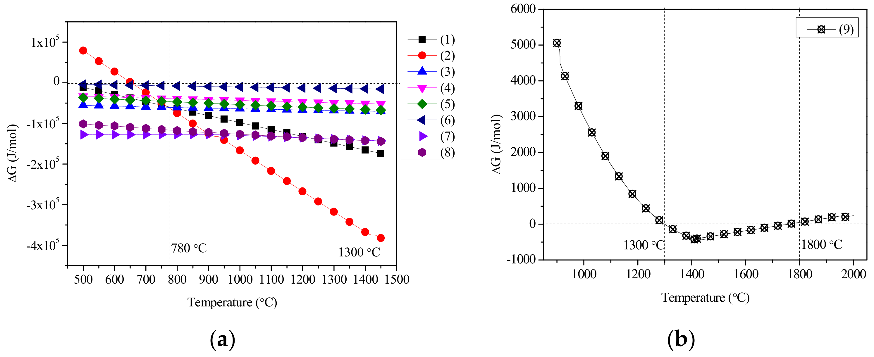
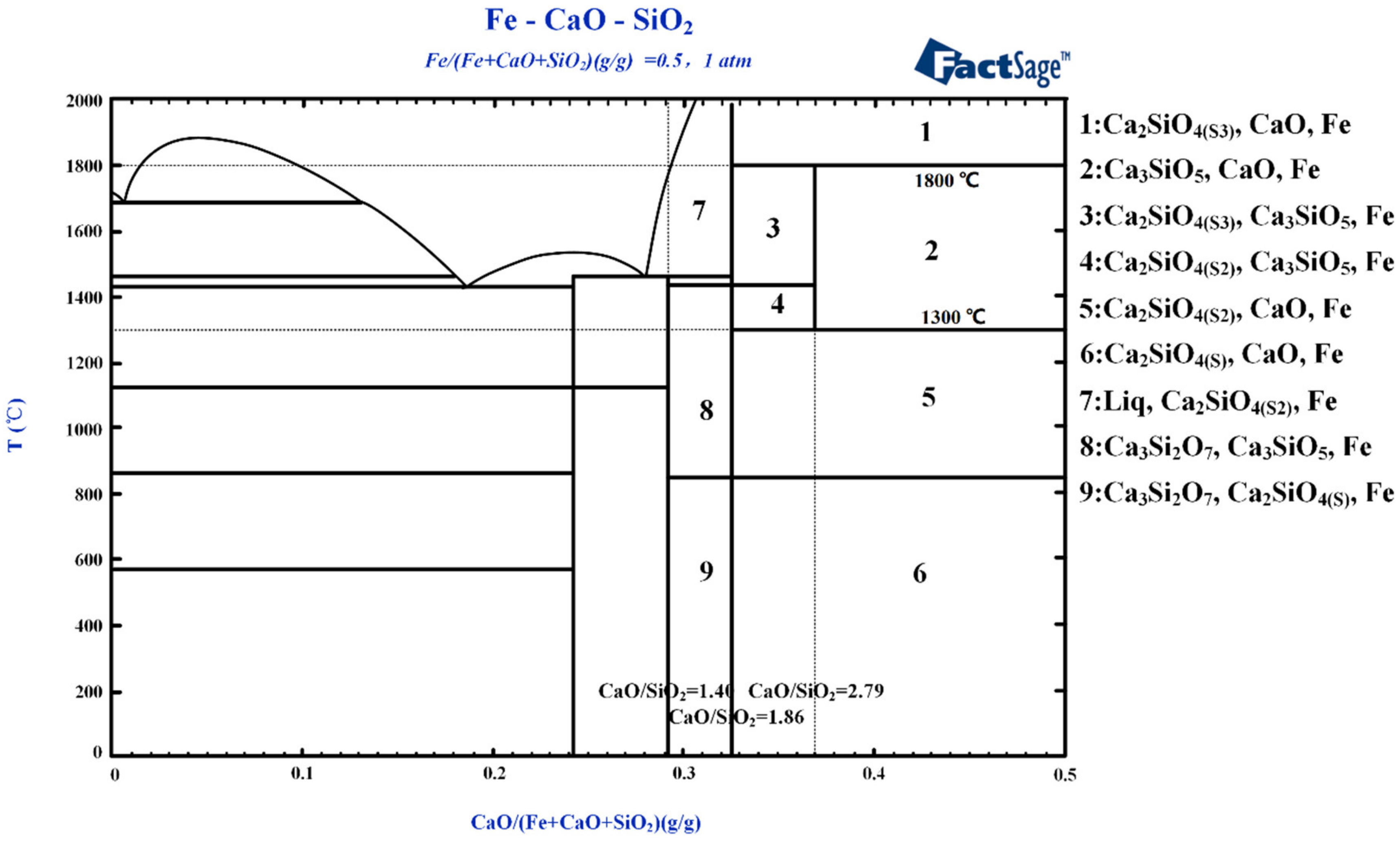
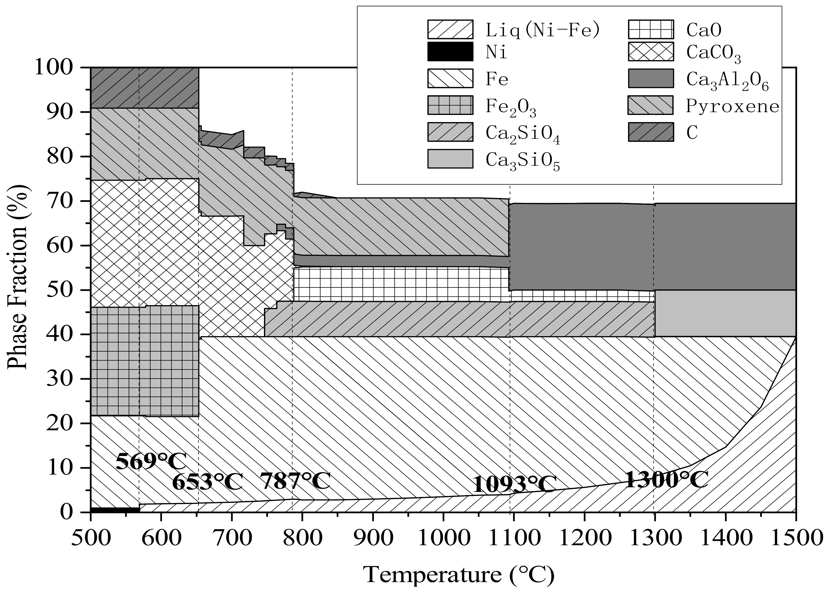
3. Thermodynamic Analysis of Coupling Reaction

In the reduction roasting process, chemical reactions including the decomposition of FeO(OH) (Goethite) and Al(OH)3 (Gibbsite), reduction of nickel and iron, reaction of iron oxides with CaO to form calcium ferrite, reaction of CaO with Al2O3 to form CaAl2O4 (CA) and Ca3Al2O6 (C3A), reaction of CaO with SiO2 to create Ca3SiO5 (C3S, alite) and Ca2SiO4 (C2S, Belite), and reaction of CaO with C2S to create C3S may occur. FeO(OH) and Al(OH)3 can decompose into Fe2O3 and Al2O3 after heating, respectively; thus, Fe2O3 and Al2O3 are used to replace the original phases in thermodynamic analysis and calculation, following the relevant chemical reaction Equations (1)–(9). Using the Reaction model in FactSage software (FactSage 6.3, Thermfact/CRCT, Montreal, Canada and GTT-Technologies, Aachen, Germany), the possible standard Gibbs free energy produced by the reactions among the main phases during reduction roasting is calculated at intervals of 10 °C between 0 °C and 2000 °C, and the relationship of temperature and standard Gibbs free energy ΔG for each equation is drawn via Origin (Origin 2019, OriginLab, Northampton, MA, USA) as shown in Figure 2 [46].
NiO + C→Ni + CO
Fe2O3 + 3C→2Fe + 3CO
Fe2O3 + 2CaO→Ca2Fe2O5
CaO + Al2O3→CaAl2O4
2CaO + CaAl2O4→Ca3Al2O6
3CaO + Al2O3→Ca3Al2O6
2CaO + SiO2→Ca2SiO4
3CaO + SiO2→Ca3SiO5
CaO + Ca2SiO4→Ca3SiO5
As shown in Figure 2a, in the temperature range 500–1450 °C, Equations (1), (3), and (8) proceed spontaneously to realize the reduction of nickel and the production of CA, C3A, C2S, C3S, and Ca2Fe2O5. In Equation (2), the temperature at the beginning of iron reduction is 653 °C. At temperatures below 780 °C, the reaction of Equation (3) consumes CaO and Fe2O3 and then produces Ca2Fe2O5; because the reaction proceeds more easily than iron reduction in Equation (2), this temperature regime is unfavorable for iron reduction. At temperatures above 780 °C, the reaction of Equation (2) proceeds before that of Equation (3); Fe2O3 is reduced to iron and the temperature for Fe2O3 reduction should be higher than 780 °C, under which nickel reduction can also occur.
Through the comparison of the ΔG–T curves of Equations (4)–(6) in Figure 2a, when the temperature is above 500 °C, CaO and Al2O3 react to produce C3A more easily. The product of CA also reacts further with CaO to produce C3A; therefore, at high temperatures, the reaction of CaO with Al2O3 finally produces the C3A phase.
Through the comparison of the ΔG–T curves of Equations (7) and (8) in Figure 2a, at 1300 °C, the reaction given by Equation (7) proceeds more easily compared to that given by Equation (8) to produce C2S. At temperatures above 1300 °C, C3S is more easily produced. From Figure 2b, only at temperatures between 1300 °C and 1800 °C does the reaction of Equation (9) occur spontaneously; then, C2Se produced early in the reaction reacts with calcium oxide to generate C3S. Combining Figure 2a,b, to acquire a cementitious material with C3A and C3S as the main phases, the temperature must be between 1300 °C and 1800 °C.
To discuss the reactant phase compositions under high temperatures when iron is not fully reduced, the phase model in FactSage software is used to determine the phase diagram for the quaternary oxide system of CaO–SiO2–Al2O3–Fe2O3 at 1350 ℃. Supposing that unreduced iron comprises 10% of the total mass of this quaternary oxide system, the resulting phase diagram is as shown in Figure 3.
The red line in Figure 3 indicates the raw material ratio of Al2O3/SiO2 = 2.66, equal to that in the laterite nickel ore. The phase composition of the quaternary oxide system varies along the red line as the CaO content changes. For a continuous increase in CaO content, the phase composition of the quaternary oxide system also changes correspondingly. For lower CaO contents (area 4 in the figure), the phase composition includes CA, Ca2SiO4, Ca2Al2SiO7, and Ca2Fe2O5. As the CaO content increases (area 3), CaO reacts with Ca3Al2SiO7 to produce C3A and C2S, and the Ca3Al2SiO7 phase disappears. With further increases in CaO content (area 2), sufficient CaO reacts with CA to form C3A and consume CA; afterward, CaO reacts with C2S to generate C3S. When the CaO content reaches area 1, C2S is fully consumed, for it reacts completely with CaO to produce C3S. Additional CaO exists in the free state.
In addition, Fe2O3 reacts with CaO at 1350 °C to produce Ca2Fe2O5, which coexists with CA, C3A, C2S, and C3S (areas 1–4) as impurities in cementitious materials. Thus, Fe2O3 should be reduced to iron to avoid yielding Ca2Fe2O5.
Figure 3 indicates that a sufficiently high CaO content (areas 1–3) can ensure the coexistence of silicate and aluminate systems independently under high temperatures. To further explore the interaction relationship of reduced iron with the silicate and aluminate systems, FactSage is used to determine the two ternary diagrams of Fe–CaO–Al2O3 and Fe–CaO–SiO2. Iron is set to comprise 50% of the whole, as shown in Figure 4 and Figure 5.
Figure 4 demonstrates that C3A is somewhat unstable unless it is produced within the temperature range 237–1540 °C. Stable C3A is produced by the reaction of aluminum oxide with CaO (areas 3–5). At temperatures below 237 °C (area 6), C3A is decomposed into CA. At temperatures higher than 1540 °C (area 1), C3A reacts with the slag liquid phase and decomposes. Reduced iron is not obviously influential on the CaO–Al2O3 system, indicating that they can coexist. For temperatures between 237 °C and 1540 °C and lower CaO contents (CaO/Al2O3 < 0.55), no C3A forms in the system. The reaction of CaO with Al2O3 under these conditions produces CaAl4O7 and CaAl2O4, which have lower calcium contents (area 7); as the CaO content increases to 0.55 < CaO/Al2O3 < 1.65 (area 7), the low-calcium-content CaAl4O7 phase disappears and the more calcium-rich Ca3Al2O6 phase is produced. CaAl2O4 ceases forming for CaO/Al2O3 > 1.65, at which point the main phases are C3A, free-state CaO, and coexistent iron (area 5), meaning that CaO/Al2O3 = 0.55 and CaO/Al2O3 = 1.65 are the composition points of CaAl2O4 and Ca3AlO6, respectively. In conclusion, when cementitious materials with the main phase of C3A are prepared, the effective mass of CaO combined with Al2O3 should meet the proportion of CaO/Al2O3 = 1.65 in the blending process, and the roasting temperature should be between 237 °C and 1540 °C.
Figure 5 indicates that C3S is also unstable outside of the temperature range 1300 °C to 1800 °C. Stable C3S is produced by the reaction of aluminum oxide with C2S (areas 2–4) within this range. When the reaction temperature is lower than 1300 °C or higher than 1800 °C (areas 1 and 5), C3S is decomposed to C2S and free-state CaO, consistent with the thermodynamic calculations shown in Figure 2b. Meanwhile, the effect of reduced iron on the CaO–SiO2 system is not significant, indicating that these three phases can coexist. At temperatures 1300 °C–1800 °C and lower CaO contents (CaO/SiO2 < 1.40), neither C3S nor C2S is found in the system. The reaction of CaO with SiO2 mainly produces CaSiO3 and Ca3Si2O7. When the ratio of CaO/SiO2 is between 1.40 and 1.86, C2S exists in the system (areas 7 and 8); when the ratio range is 1.86 to 2.79, C2S and C3S can coexist in the system (areas 3 and 4); when the ratio range exceeds 2.79, C3S, free-state CaO, and coexistent Fe (area 2) are the main phases, meaning that CaO/SiO2 = 1.40 and CaO/SiO2 = 1.86 are the composition points of Ca3Si2O7 and C2S, respectively. In conclusion, when the cementitious materials with the main phase of C3S are prepared, the effective mass of CaO combined with SiO2 should meet the proportion CaO/SiO2 = 2.79 in the blending process, and the roasting temperature should be between 1300 °C and 1800 °C.
With powdered carbon as the reducing agent, laterite nickel ore as the raw material, and CaO as the additive, the theoretical analysis results of the changes in the phase composition of the reactants during heating are calculated under a protective CO atmosphere, by the equipment module in the FactSage software. As shown in Table 2, the reactant proportion was the same. Figure 6 shows the calculation result of the theoretical reaction product, which analyzes the phase change of the system from 500 °C to 1500 °C in a temperature interval of 50 °C.
It can be seen from Figure 6 that in the reaction in the low temperature zone (<569 °C), the phases formed are mainly carbon, pyroxene, CaCO3, Fe2O3, nickel, and partly reduced iron. When the temperature exceeds 569 °C, a liquid iron–nickel phase is formed with a high content of nickel; the ratio of this liquid alloy phase increases with increasing of temperature. At temperatures above 653 °C, most of the Fe2O3 and carbon reactants are consumed to form iron. For temperatures above 787 °C, CaCO3 is decomposed into CaO, part of which reacts with SiO2 and Al2O3 to generate C2S and some Ca3Al2O6, while the pyroxene is consumed. When the reaction temperature is between 1093 °C and 1300 °C, there is no obvious change in each phase, and the main components of liquid iron–nickel alloy, iron, CaO, Ca3Al2O6, and C2S. However, at temperatures above 1300 °C, C3S is formed by the reaction of CaO and C2S. Under high-temperature reaction, the final products are liquid iron–nickel alloy, Ca3Al2O6, and C3S.
According to the above-mentioned thermodynamic analysis, it is feasible to prepare a cementitious material of C3A and C3S by the reduction roasting of laterite nickel ore after the appropriate proportioning. However, in order to ensure the sufficient reduction of nickel and iron as well as the effective production of C3A and C3S, the roasting temperature must be controlled by stages.
The reduction temperature of Fe2O3 should be controlled at 780–1220 °C since Fe2O3 reacts with CaO to form Ca2Fe2O5 which affects iron reduction. Thus, in order to ensure complete iron reduction and prevent the formation of low-melting-point liquid fayalite (which melts at 1220 °C) by Fe2O3 and SiO2, this temperature should be maintained for a certain period of time. Under these conditions, C2S and a small amount of Ca3Al2O6 can be produced. After the sufficient reduction of iron, the temperature is increased again and then maintained at 1300–1540 °C (the temperature range for forming stable existent C3S is 1300–1800 °C, that for the decomposition of pyroxene is 1093 °C, and that for stable existent C3A is 237–1540 °C). In this regime, the formation of C3S and the reaction of pyroxene after decomposition with CaO to form Ca3Al2O6 are accomplished. Finally, the samples are cooled by fast cooling; tricalcium silicate is metastable at normal temperatures with this treatment.

4. Experiments and Results

To verify the accuracy of the above thermodynamic analyses and calculations, coupled experimental studies are conducted under different reaction conditions. Three different control processes are set using three 8 g samples placed in separate Al2O3 crucibles. Each crucible is placed in airtight tube-type resistance furnace with the heating rate set to 10°C/min. The controlling processes for the three samples are as follows:
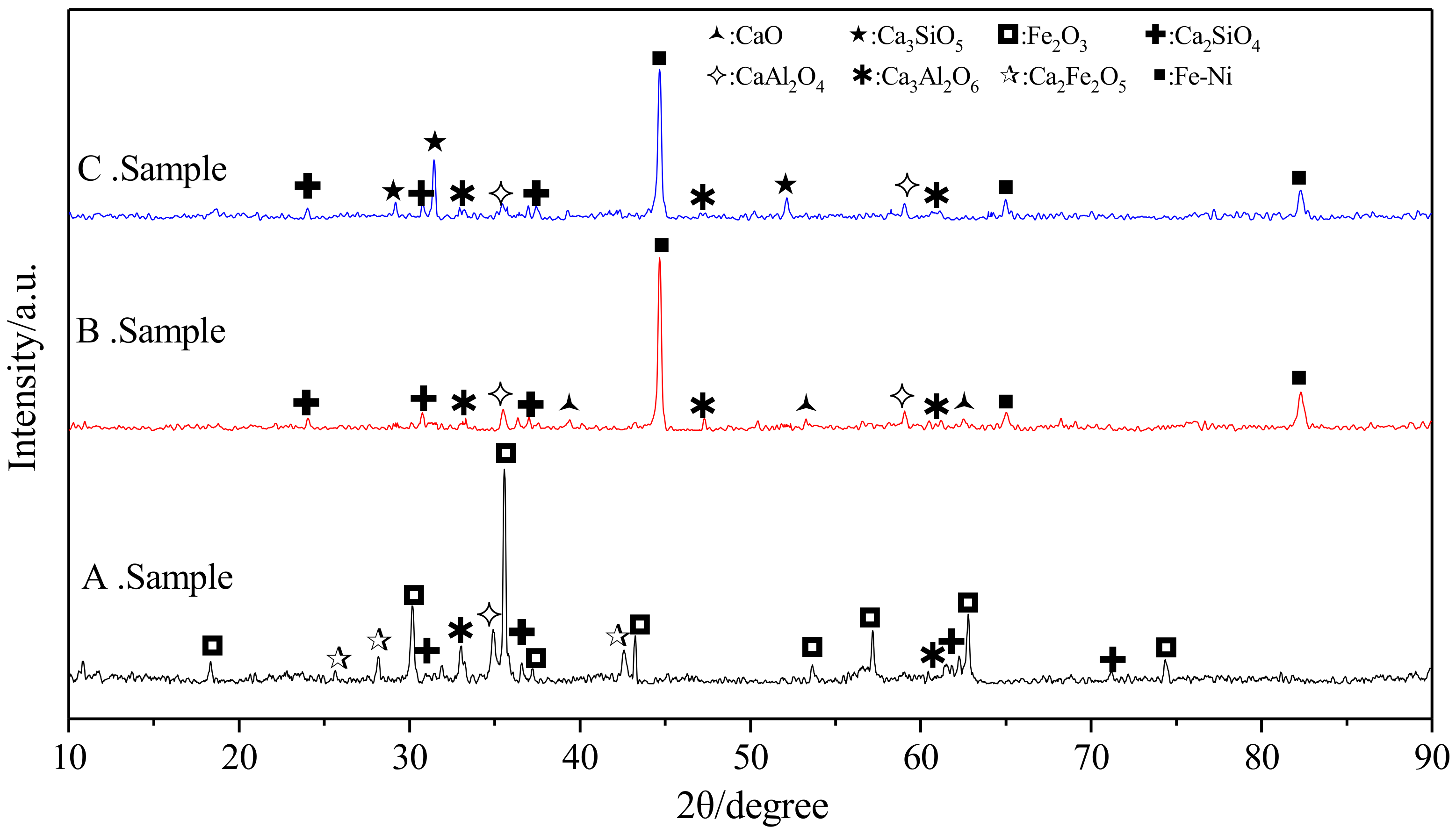
  • No atmospheric protection; the temperature is increased from indoor ambient temperature to 1450 °C and maintained for 1 h before cooling to indoor temperature to obtain product A.
  • At the flow rate of 60 mL/h under the atmospheric protection of CO, the temperature continues to rise from room temperature to 1000 °C, maintained for 2 h, and then increased to 1450 °C and maintained for 1 h. Product B was obtained after furnace cooling to room temperature.
  • The period of cooling applied in (2) is changed. The atmosphere conditions and control process of the temperature increase to 1450 °C are the same as those used for obtaining sample B. After maintaining the temperature of 1450 °C for 1 h, by using fast cooling, product C was obtained.
Finally, the obtained reaction samples were examined by XRD and scanning electron microscopy-energy-dispersive X-ray spectroscopy (SEM-EDS). The XRD equipment was the same as that used for raw material analysis; the SEM analysis equipment was type VEGA II XMU (TESCAN Company, Brno, Czechia); the EDS analysis equipment was type 7718 (Oxford Instruments, London, UK). The XRD and SEM-EDS analysis results are shown in Figure 7 and Figure 8, respectively.
Iron oxide comprises more than 45% of the total sample mass, and the ferronickel alloy is 40% of the total mass in the theoretical reaction product. Therefore, it can be seen from the XRD pattern that the intensity of the diffraction peaks of iron–nickel alloy and iron oxide is higher than that of other phases.
As can be seen from the XRD analysis results, sample A shows incomplete iron reduction, attributed to the lack of atmosphere protection; iron is present as unreacted Fe2O3 and Ca2Fe2O5 after reacting with CaO. The consumption of CaO causes the reduction of CaO/Al2O3 and CaO/SiO2. The diffraction peaks of the low calcium phase appear obviously in the XRD pattern of the reaction products, such as CaAl2O4 and Ca2SiO4. At the same time, the diffraction peaks of Ca3Al2O6 have a weak diffraction peak, which is consistent with the analysis results in Figure 3. At 1000 °C for 2h, sample B reacts in a reducing atmosphere to ensure that the nickel–iron is completely reduced to form an iron–nickel alloy, and is then held at 1450 °C for 1 h to form C3S. However, as a result of furnace cooling, C3S is decomposed into C2S and CaO phases. Therefore, the final products of sample B are iron, CaO, Ca2SiO4, CaAl2O4, and Ca3Al2O6, which are consistent with the analysis results of Figure 4 and Figure 5. Sample C uses the same heating control method as sample B under the protection of CO to achieve the reduction of nickel–iron to form iron–nickel alloys, C3S and C3A. C3S avoids the large-scale decomposition using rapid cooling. The final products are iron, C3S, and Ca3Al2O6, and the decomposition products are CaAl2O4 and Ca2SiO4, which show obviously stronger XRD peaks than that of Ca2SiO4 in sample B. Simultaneously, the SEM-EDS analysis and scanning of sample C show that the morphology of the product is composed of many iron grains with different grain diameters and the cementing material in them. The distributions of nickel and iron are the same; those of calcium, aluminum, silicon, and oxygen are the same, and clear boundaries are observed between the ferronickel alloy and the cementitious materials. The analytical results of theoretical products shown in Figure 6 are consistent with the above analytical results.

5. Conclusions

  • For the preparation of high-temperature coexisting cementitious materials such as ferronickel alloy, C3S, C2S, etc., it is feasible to reduce and roast laterite nickel ore after proportioning.
  • It is necessary to control the coupling reaction temperature in stages. The reduction temperature of Fe2O3 is controlled at 780–1220 °C, the formation temperature of C3S is controlled at 1300–1800 °C, and the stability of C3S is controlled at 237–1540 °C. Fast cooling must be applied in order to obtain a metastable C3S phase.
  • At the reducing atmosphere protection of CO, the first reaction stage is holding at 1000 °C for 2 h, the second reaction stage is holding at 1450 °C for 1 h, and fast cooling is used. In this process, ferronickel alloy, C3S, and Ca3Al2O6 laterite nickel ore are reduced and roasted, and the decomposition products are Ca2SiO4 and CaAl2O4 to obtain the final products.
  • The reduction of iron has a significant effect on the formation of C3S. When iron is insufficiently reduced, calcium ferrite and other phases are formed in combination with CaO, hindering the formation of C3S. The necessary condition for the formation of C3S is the sufficient reduction of iron.

Author Contributions

Methodology, J.Z., X.L., C.Z. and Y.C.; software, J.Z., X.L., C.Z. and Y.C.; validation, J.Z. and X.L.; formal analysis, C.Z. and Y.C.; investigation, J.Z., X.L., C.Z. and Y.C.; data curation, C.Z. and Y.C.; writing—original draft preparation, J.Z.; writing—review and editing, R.S. and G.Q. All authors have read and agreed to the published version of the manuscript.

Funding

The work was financially supported by the National Natural Science Foundation of China (51874224) and Project of young talents in basic research of Natural Science in Shaanxi Province (2014JQ7282).

Conflicts of Interest

The authors declare no conflict of interest.

References

  1. Pollock, T.M.; Tin, S. Nickel-Based Superalloys for Advanced Turbine Engines: Chemistry, Microstructure and Properties. J. Propuls. Power 2006, 22, 361–374. [Google Scholar] [CrossRef]
  2. Hasanbeigi, A.; Arens, M.; Price, L. Alternative emerging ironmaking technologies for energy-efficiency and carbon dioxide emissions reduction: A technical review. Renew. Sustain. Energy Rev. 2014, 33, 645–658. [Google Scholar] [CrossRef]
  3. Moskalyk, R.; Alfantazi, A. Nickel laterite processing and electrowinning practice. Miner. Eng. 2002, 15, 593–605. [Google Scholar] [CrossRef]
  4. Petrus, H.T.B.M.; Rhamdani, A.R.; Putera, A.D.P.; Warmada, I.W.; Yuliansyad, A.T.; Perdana, I. Kinetics study of carbon raiser on the reduction of nickel laterite from Pomalaa, Southeast Sulawesi. In IOP Conference Series: Materials Science and Engineering, Proceedings of the Second International Conference on Chemical Engineering (ICCE) UNPAR, Bandung, Indonesia, 26–27 October 2016; IOP Publishing Ltd: Bristol, UK, 2016; Volume 126, pp. 12–19. [Google Scholar] [CrossRef]
  5. Kostiantyn, T.; Dmitry, B.; Vinod, S.; Gleb, Y. Ten years left to redesign lithium-ion batteries. Nature 2018, 559, 467–470. [Google Scholar]
  6. Brown, T.J.; Wrighton, C.E.; Idoine, N.E.; Raycraft, E.R.; Shaw, R.A.; Deady, E.A.; Rippingale, J.; Bide, T. World Mineral Production 2011–2014; World Mineral Production Series; British Geological Survey: Keyworth, UK, 2017. [Google Scholar]
  7. Crundwell, F.K.; Moats, M.S.; Ramachandran, V.; Robinson, T.G.; Davenport, W.G. Extractive Metallurgy of Nickel, Cobalt and Platinum Group Metals, 1st ed.; Elsevier: Oxford, UK, 2011; pp. 21–37. [Google Scholar]
  8. Farrokhpay, S.; Filippov, L.; Fornasiero, D. Pre-concentration of nickel in laterite ores using physical separation methods. Miner. Eng. 2019, 141, 105892. [Google Scholar] [CrossRef]
  9. Xu, D.; Liu, L.X.; Quast, K.; Addai-Mensah, J.; Robinson, D.J. Effect of nickel laterite agglomerate properties on their leaching performance. Adv. Powder Technol. 2013, 24, 750–756. [Google Scholar] [CrossRef]
  10. Li, X.M.; Bai, T.T.; Zhao, J.X.; Li, W.F.; Li, Z.G.; Cui, Y.R. Status and Progress of Metallurgical Technology on Laterite-Nickel Ore. Mater. Rev. 2014, 28, 112–116. [Google Scholar]
  11. Liu, D.X. Recent Development in Nickel and Cobalt Recovery Technologies from Laterite. Nonferrous Met. 2002, 3, 6–10. [Google Scholar]
  12. Ma, X.B. Study on Preparing Ferronickel from Laterite by Roasting-Reducing Smelting Method. Master Thesis, Central South University, Hunan, China, 1 May 2010. [Google Scholar]
  13. Ray, H.; Sridhar, R.; Abraham, K. Extraction of Nonferrous Metals; Affiliated East-west Press (pvt.) Ltd.: NewDelhi, India, 1985. [Google Scholar]
  14. Butt, C.R.; Cluzel, D. Nickel laterite ore deposits: Weathered serpentinites. Elements 2013, 9, 123–128. [Google Scholar] [CrossRef]
  15. Pintowantoro, S.; Abdul, F. Selective Reduction of Laterite Nickel Ore. Mater. Trans. 2019, 60, 2245–2254. [Google Scholar] [CrossRef]
  16. Agatzini-Leonardou, S.; Tsakiridis, P.E.; Oustadakis, P.; Karidakis, T.; Katsiapi, A. Hydrometal lurgical process for the separation and recovery of nickel from sulphate heap leach liquor of nickeliferrous laterite ores. Miner. Eng. 2009, 22, 1181–1192. [Google Scholar] [CrossRef]
  17. Xu, M.; Xu, Q.; Liu, R.Q. Exploitation of Laterite-Nickel Mineral Resources and Technology Advances. Multipurp. Util. Miner. Resour. 2009, 3, 28–30. [Google Scholar]
  18. Chen, J.B.; Xu, J.H. Status quo of nickel mineral resources of our country and countermeasures. Express Inf. Min. Ind. 2006, 25, 1–3, 37. [Google Scholar]
  19. Janwong, A. The Agglomeration of Nickel Laterite Ore. Ph.D. Thesis, University of Utah, Salt Lake City, UT, USA, December 2012. [Google Scholar]
  20. Andika, R.; Astuti, W.; Syafriadi; Nurjaman, F. Effect of flux addition and reductant type in smelting process of Indonesian limonite ore in electric arc furnace. In IOP Conference Series: Materials Science and Engineering, Proceedings of the The 2nd Mineral Processing and Technology International Conference, Tangerang, Banten Province, Indonesia, 1 November 2018; IOP Publishing Ltd: Bristol, UK, 2018; Volume 478. [Google Scholar]
  21. Farrokhpay, S.; Cathelineau, M.; Blancher, S.B.; Laugier, O.; Filippov, L. Characterization of Weda Bay nickel laterite ore from Indonesia. J. Geochem. Explor. 2019, 196, 270–281. [Google Scholar] [CrossRef]
  22. Farrokhpay, S.; Fornasiero, D.; Filippov, L. Upgrading nickel in laterite ores by flotation. Miner. Eng. 2018, 121, 100–106. [Google Scholar] [CrossRef]
  23. Farrokhpay, S.; Filippov, L. Challenges in processing nickel laterite ores by flotation. Int. J. Miner. Process. 2016, 151, 59–67. [Google Scholar] [CrossRef]
  24. Quast, K.; Connor, J.N.; Skinner, W.; Robinson, D.J.; Addai-Mensah, J. Preconcentration strategies in the processing of nickel laterite ores Part 1: Literature review. Miner. Eng. 2015, 79, 261–268. [Google Scholar] [CrossRef]
  25. Quast, K.; Connor, J.N.; Skinner, W.M.; Robinson, D.J.; Li, J.; Addai-Mensah, J. Preconcentration strategies in the processing of nickel laterite ores part 2: Laboratory experiments. Miner. Eng. 2015, 79, 269–278. [Google Scholar] [CrossRef]
  26. Li, J.; Li, X.; Hu, Q.; Wang, Z.; Zhou, Y.; Zheng, J.; Liu, W.; Li, L. Effect of pre-roasting on leaching of laterite. Hydrometallurgy 2009, 99, 84–88. [Google Scholar] [CrossRef]
  27. Lu, J.; Liu, S.; Shangguan, J.; Du, W.; Pan, F.; Yang, S. The effect of sodium sulphate on the hydrogen reduction process of nickel laterite ore. Miner. Eng. 2013, 49, 154–164. [Google Scholar] [CrossRef]
  28. Chen, S.-L.; Guo, X.; Shi, W.-T.; Li, N. Extraction of valuable metals from low-grade nickeliferous laterite ore by reduction roasting-ammonia leaching method. J. Central South Univ. Technol. 2010, 17, 765–769. [Google Scholar] [CrossRef]
  29. Zhu, Z.; Chen, M.-H.; Abernathy, E.; Icenogle, J.; Zhou, S.; Wang, C.; Zhao, C.; Wang, Y.; Chen, H.; Si, Y.; et al. Analysis of complete genomes of the rubella virus genotypes 1E and 2B which circulated in China, 2000–2013. Sci. Rep. 2016, 6, 39025. [Google Scholar] [CrossRef]
  30. Jiang, M.; Sun, T.; Liu, Z.; Kou, J.; Liu, N.; Zhang, S. Mechanism of sodium sulfate in promoting selective reduction of nickel laterite ore during reduction roasting process. Int. J. Miner. Process. 2013, 123, 32–38. [Google Scholar] [CrossRef] [Green Version]
  31. Ma, B.; Wang, C.; Yang, W.; Yin, F.; Chen, Y. Screening and reduction roasting of limonitic laterite and ammonia-carbonate leaching of nickel–cobalt to produce a high-grade iron concentrate. Miner. Eng. 2013, 106–113. [Google Scholar] [CrossRef]
  32. Oliveira, V.D.A.; Dos Santos, C.G.; Brocchi, E.D.A. Assessing the Influence of NaCl on the Reduction of a Siliceous Laterite Nickel Ore Under Caron Process Conditions. Met. Mater. Trans. A 2019, 50, 1309–1321. [Google Scholar] [CrossRef]
  33. Landers, M.; Gilkes, R. Dehydroxylation and dissolution of nickeliferous goethite in New Caledonian lateritic Ni ore. Appl. Clay Sci. 2007, 35, 162–172. [Google Scholar] [CrossRef]
  34. Sarbishei, S.; Khajavi, L.T. Kinetic analysis on nickel laterite ore calcination using model-free and model-fitting methods. Miner. Eng. 2019, 136, 129–139. [Google Scholar] [CrossRef]
  35. Oliveira, V.D.A.; Lana, R.D.J.T.; Coelho, H.C.D.S.; Brigolini, G.J.S.; Dos Santos, C.G. Kinetic Studies of the Reduction of Limonitic Nickel Ore by Hydrogen. Met. Mater. Trans. A 2020, 51, 1418–1431. [Google Scholar] [CrossRef]
  36. Sarbishei, S.; Khajavi, L.T. The effect of sulfur content of rotary kiln fuel on the composition of nickel laterite calcine. Fuel 2020, 280, 118648. [Google Scholar] [CrossRef]
  37. Wang, X.F. Simple analysis on pyrometallurgy (RKEF Method) of laterite-nickel ore. Tech. Inno. App. 2013, 1, 89. [Google Scholar]
  38. Wang, C.Y.; Yin, F.; Chen, Y.Q.; Wang, Z.; Wang, J. Worldwide processing technologies and progress of nickel laterites. In Proceedings of the National Academic Conference of Hydrometallurgy in 2008, Ganzhou, China, 1 April 2008; pp. 1–8. [Google Scholar]
  39. Sun, Y.Y.; He, Y.M.; Wang, Y. An elementary introduction on ferronickel technological process. Nonferrous Met. Des. 2008, 35, 7–13. [Google Scholar]
  40. Zhang, B.S.; Jiang, K.X.; Wang, H.B.; Feng, Y.P. Progress of pyrometallurgical smelting technologies for laterite-nickel ore in China. Nonferrous Met. Eng. Res. 2012, 33, 16–19. [Google Scholar]
  41. He, F. Research on direct reduction roasting and magnetic separation of low-grade laterite nickel ore. Hot Work. Technol. 2012, 41, 16–18, 21. [Google Scholar]
  42. Liu, J.J.; Hu, G.R.; Peng, Z.D. The latest and future development of laterite nickel ore processing technology. Rare Met. Cem. Carbides 2011, 39, 62–66. [Google Scholar]
  43. Zhao, G. Simple analysis on ferronickel production technology and its development prospect. Ind. Sci. Trib. 2011, 10, 96–97. [Google Scholar]
  44. Hu, L.B. Analysis of nickel-iron production (I). Ferro-alloys 2009, 40, 6–10. [Google Scholar]
  45. Zhu, J.W. Ferronickel smelting process comparison: Blast furnace, electric furnace and rotary kiln. Xinjiang Nonferrous Met. 2011, 34, 53. [Google Scholar]
  46. Shi, R.; Zhao, J.; Li, X.; Zou, C.; Cui, Y.; Qiu, G. Experimental Study on the Preparation of Cementing Materials by Direct Reduction Coupling of a Hematite-Carbon Base. Metals 2020, 10, 1086. [Google Scholar] [CrossRef]
Figure 1. Laterite nickel ore XRD analysis.
Materials 13 04992 g001
Figure 2. Laterite nickel ore coupling reaction ΔGT: (a) Equations (1)−(8); (b) Equation (9).
Materials 13 04992 g002
Figure 3. Phase diagram of quaternary oxide system CaO–SiO2–Al2O3–Fe2O3 at 1350 °C.
Materials 13 04992 g003
Figure 4. Ternary diagram of Fe–CaO–Al2O3.
Materials 13 04992 g004
Figure 5. Ternary phase diagram of Fe–CaO–SiO2 [46].
Materials 13 04992 g005
Figure 6. Diagram of variations in laterite nickel ore reduction roasting products.
Materials 13 04992 g006
Figure 7. XRD analysis for reduction roasting products of laterite nickel ore.
Materials 13 04992 g007
Figure 8. SEM–EDS analysis chart of sample C: (a) SEM analysis; (b) EDS analysis of Fe; (c) EDS analysis of Ni; (d) EDS analysis of Ca; (e) EDS analysis of Al; (f) EDS analysis of Si; (g) EDS analysis of O.
Materials 13 04992 g008
Table 1. Chemical components of laterite nickel ore (%wt.).
ComponentsNiOFe2O3FeOSiO2Al2O3CaOMgOWater
Content1.5465.230.443.308.770.961.5117.31
Table 2. Laterite nickel ore reduction roasting burden sheet (%wt.).
CompositionLaterite Nickel OreCaOC
Ratio68.4219.0312.55
Publisher’s Note: MDPI stays neutral with regard to jurisdictional claims in published maps and institutional affiliations.

