Capabilities and Limitations of Fire-Shaping to Produce Glass Nozzles


Abstract
:
1. Introduction
2. Results
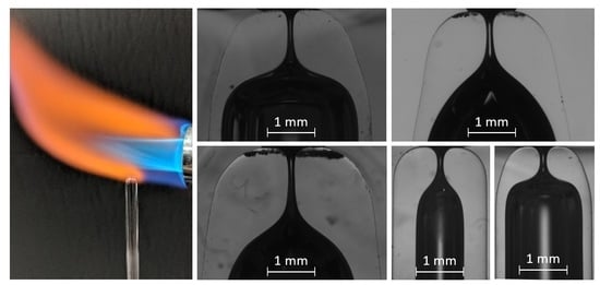
2.1. Effect of the Heating Time
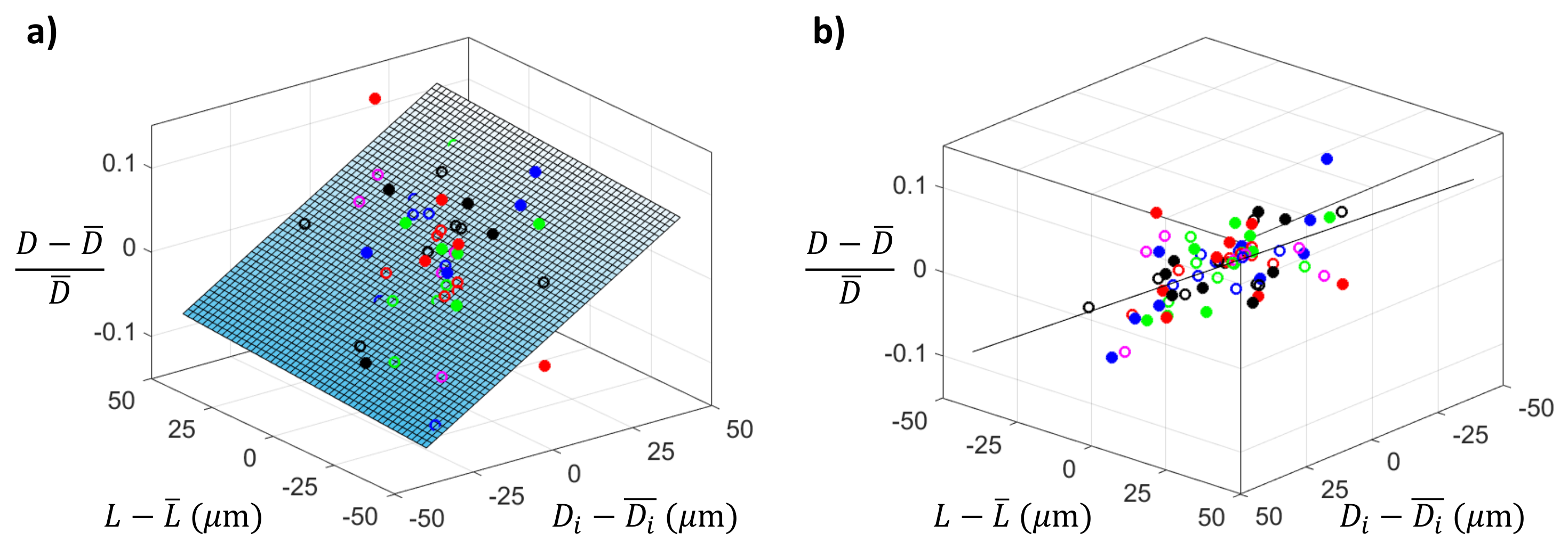
2.2. Effect of the Geometrical Tolerances of the Capillary
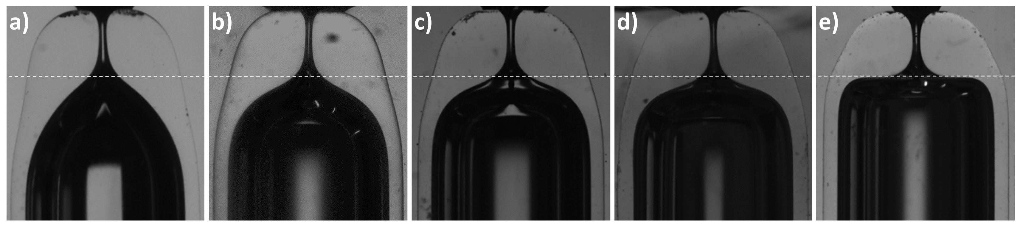
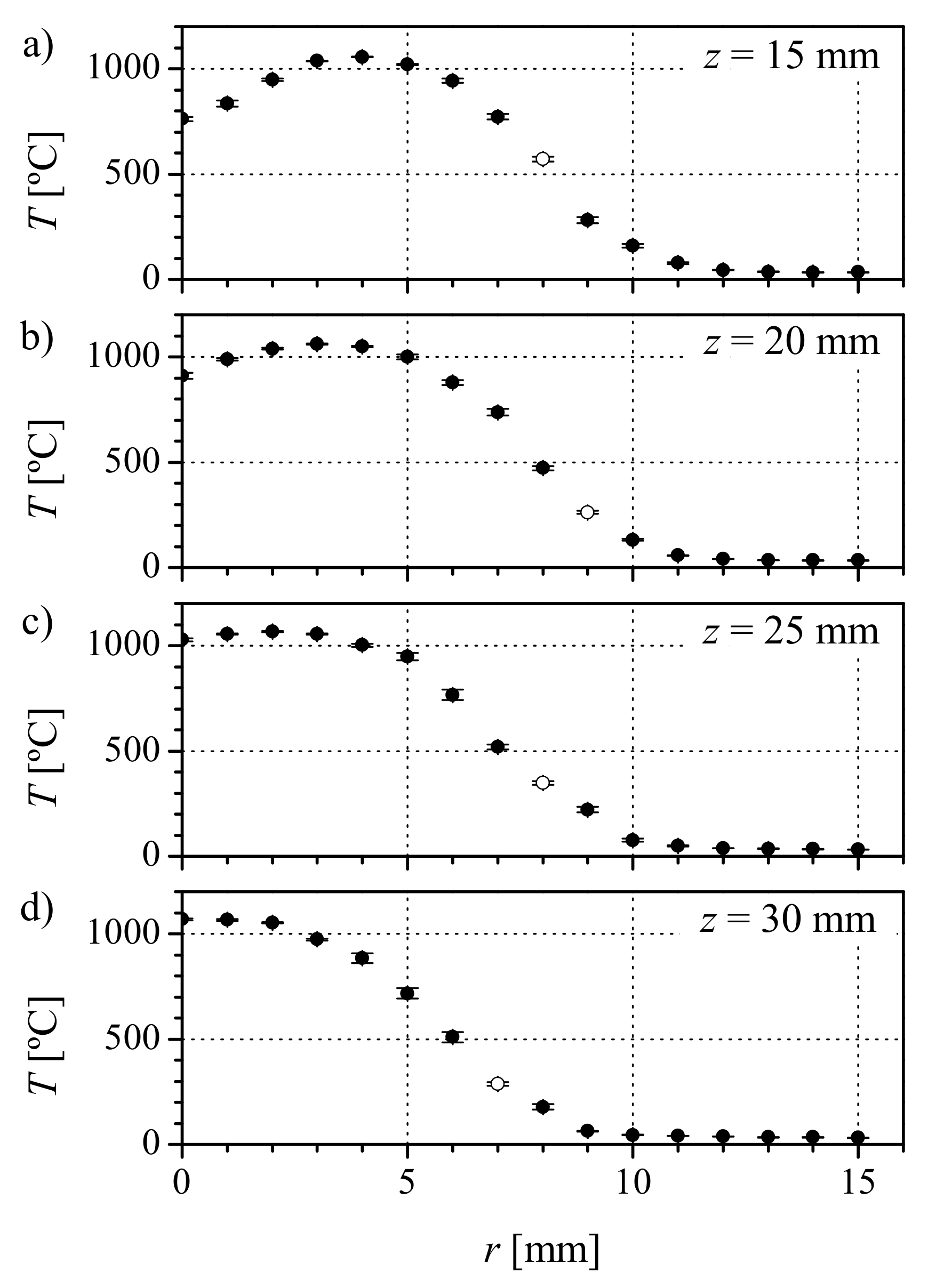
2.3. Effect of the Heating Position
2.4. Effect of the Capillary Geometry: Inner Diameter and Thickness
3. Discussion
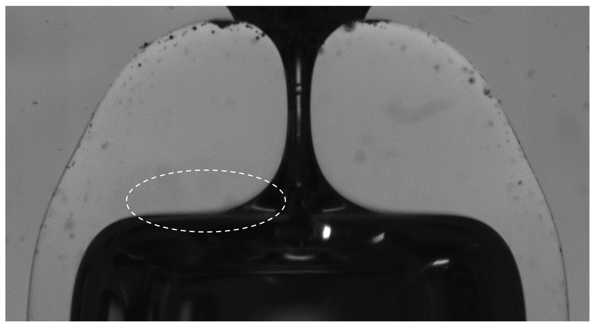
Application in Flow Focusing to Prevent Whipping
4. Materials and Methods
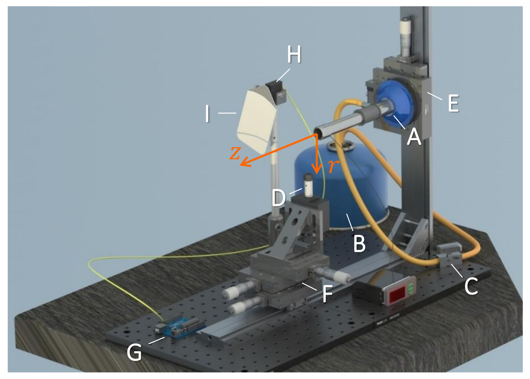
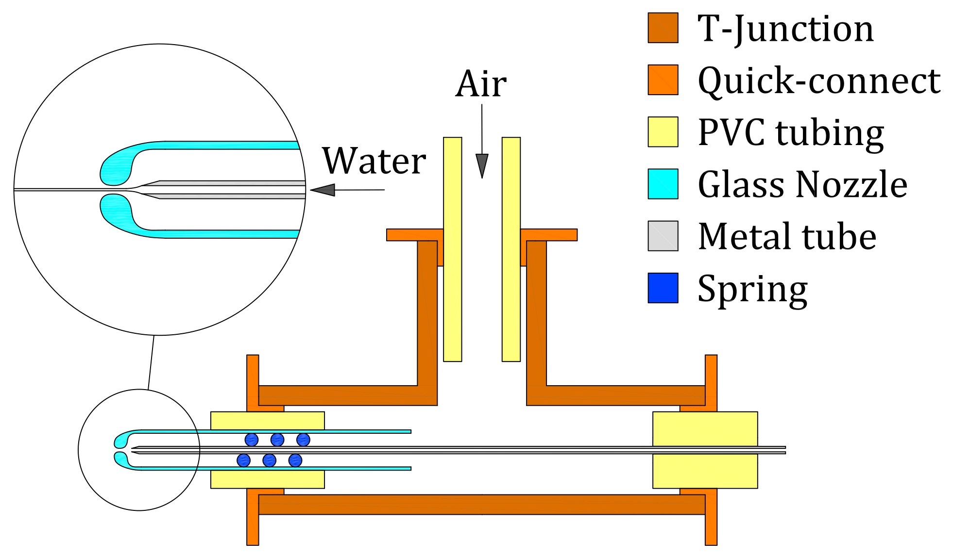
4.1. Fire-Shaping Setup
4.2. Capillaries and Nozzles Geometries
4.3. Gaseous Flow-Focusing
Author Contributions
Funding
Acknowledgments
Conflicts of Interest
References
- Sackmann, E.K.; Fulton, A.L.; Beebe, D.J. The present and future role of microfluidics in biomedical research. Nature 2014, 507, 181–189. [Google Scholar] [CrossRef]
- Shang, L.; Cheng, Y.; Zhao, Y. Emerging Droplet Microfluidics. Chem. Rev. 2017, 117, 7964–8040. [Google Scholar] [CrossRef]
- Guerrero, J.; Chang, Y.; Fragkopoulos, A.A.; Fernández-Nieves, A. Capillary-Based Microfluidics-Coflow, Flow-Focusing, Electro-Coflow, Drops, Jets, and Instabilities. Small 2020, 16, 1904344. [Google Scholar] [CrossRef]
- Montanero, J.M.; Gañán-Calvo, A.M. Dripping, jetting and tip streaming. Rep. Prog. Phys. 2020, 83, 097001. [Google Scholar] [CrossRef]
- Nielsen, A.V.; Beauchamp, M.J.; Nordin, G.P.; Woolley, A.T. 3D Printed Microfluidics. Annu. Rev. Anal. Chem. 2020, 13, 45–65. [Google Scholar] [CrossRef]
- Utada, A.S.; Lorenceau, E.; Link, D.R.; Kaplan, P.D.; Stone, H.A.; Weitz, D.A. Monodisperse Double Emulsions Generated from a Microcapillary Device. Science 2005, 308, 537–541. [Google Scholar] [CrossRef] [PubMed] [Green Version]
- Comunian, T.A.; Ravanfar, R.; Alcaine, S.D.; Abbaspourrad, A. Water-in-oil-in-water emulsion obtained by glass microfluidic device for protection and heat-triggered release of natural pigments. Food Res. Int. 2018, 106, 945–951. [Google Scholar] [CrossRef] [PubMed]
- Benson, B.R.; Stone, H.A.; Prud’homme, R.K. An “off-the-shelf” capillary microfluidic device that enables tuning of the droplet breakup regime at constant flow rates. Lab Chip 2013, 13, 4507. [Google Scholar] [CrossRef] [PubMed] [Green Version]
- Bandulasena, M.V.; Vladisavljević, G.T.; Odunmbaku, O.G.; Benyahia, B. Continuous synthesis of PVP stabilized biocompatible gold nanoparticles with a controlled size using a 3D glass capillary microfluidic device. Chem. Eng. Sci. 2017, 171, 233–243. [Google Scholar] [CrossRef] [Green Version]
- Bandulasena, M.V.; Vladisavljević, G.T.; Benyahia, B. Versatile reconfigurable glass capillary microfluidic devices with Lego® inspired blocks for drop generation and micromixing. J. Colloid Interface Sci. 2019, 542, 23–32. [Google Scholar] [CrossRef]
- DePonte, D.P.; Weierstall, U.; Schmidt, K.; Warner, J.; Starodub, D.; Spence, J.C.H.; Doak, R.B. Gas dynamic virtual nozzle for generation of microscopic droplet streams. J. Phys. D Appl. Phys. 2008, 41, 195505. [Google Scholar] [CrossRef] [Green Version]
- Gañán-Calvo, A.M. Generation of Steady Liquid Microthreads and Micron-Sized Monodisperse Sprays in Gas Streams. Phys. Rev. Lett. 1998, 80, 285–288. [Google Scholar] [CrossRef]
- Bayram, A.; Serhatlioglu, M.; Ortac, B.; Demic, S.; Elbuken, C.; Sen, M.; Solmaz, M.E. Integration of glass micropipettes with a 3D printed aligner for microfluidic flow cytometer. Sens. Actuator A Phys. 2018, 269, 382–387. [Google Scholar] [CrossRef] [Green Version]
- Weierstall, U.; Spence, J.C.H.; Doak, R.B. Injector for scattering measurements on fully solvated biospecies. Rev. Sci. Instrum. 2012, 83, 035108. [Google Scholar] [CrossRef] [PubMed]
- Beyerlein, K.R.; Adriano, L.; Heymann, M.; Kirian, R.; Knoska, J.; Wilde, F.; Chapman, H.N.; Bajt, S. Ceramic micro-injection molded nozzles for serial femtosecond crystallography sample delivery. Rev. Sci. Instrum. 2015, 86, 125104. [Google Scholar] [CrossRef] [Green Version]
- Piotter, V.; Klein, A.; Plewa, K.; Beyerlein, K.R.; Chapman, H.N.; Bajt, S. Development of a ceramic injection molding process for liquid jet nozzles to be applied for X-ray free-electron lasers. Microsyst. Technol. 2018, 24, 12471252. [Google Scholar] [CrossRef]
- Nelson, G.; Kirian, R.A.; Weierstall, U.; Zatsepin, N.A.; Faragó, T.; Baumbach, T.; Wilde, F.; Niesler, F.B.P.; Zimmer, B.; Ishigami, I.; et al. Three-dimensional-printed gas dynamic virtual nozzles for X-ray laser sample delivery. Opt. Express 2016, 24, 1515–1530. [Google Scholar] [CrossRef]
- Knoška, J.; Adriano, L.; Awel, S.; Beyerlein, K.R.; Yefanov, O.; Oberthuer, D.; Peña Murillo, E.; Roth, N.; Sarrou, I.; Villanueva-Perez, P.; et al. Ultracompact 3D microfluidics for time-resolved structural biology. Nat. Commun. 2020, 11, 657. [Google Scholar] [CrossRef] [Green Version]
- Wei, C.Y.; Yu, C.Z.; Wu, J.J.; Li, J.W.; Li, S.S.; Dai, S.J.; Li, T.J. Easy-to-operate fabrication of tapered glass capillaries for microdroplet generation. J. Micromech. Microeng. 2019, 29, 037001. [Google Scholar] [CrossRef]
- Switzer, G.L. A versatile system for stable generation of uniform droplets. Rev. Sci. Instrum. 1991, 62, 2765–2771. [Google Scholar] [CrossRef]
- Levenstein, M.; Bawazer, L.; Nally, C.M.; Marchant, W.; Gong, X.; Meldrum, F.; Kapur, N. A reproducible approach to the assembly of microcapillaries for double emulsion production. Microfluid. Nanofluid. 2016, 20, 143. [Google Scholar] [CrossRef] [Green Version]
- Chapman, H.N.; Fromme, P.; Barty, A.; White, T.A.; Kirian, R.A.; Aquila, A.; Hunter, M.S.; Schulz, J.; DePonte, D.P.; Weierstall, U.; et al. Femtosecond X-ray protein nanocrystallography. Nature 2011, 470, 73–79. [Google Scholar] [CrossRef] [PubMed]
- Cabezas, M.G.; Rubio, M.; Rebollo-Muñoz, N.; Herrada, M.A.; Montanero, J.M. Global stability analysis of axisymmetric liquid-liquid flow focusing. J. Fluid Mech. 2021, in press. [Google Scholar]
- Ponce-Torres, A.; Ortega, E.; Rubio, M.; Rubio, A.; Vega, E.J.; Montanero, J.M. Gaseous flow focusing for spinning micro and nanofibers. Polymer 2019, 178, 121623. [Google Scholar] [CrossRef]
- Muñoz-Sánchez, B.N.; Cabezas, M.G. Borosilicate nozzles manufactured by reproducible fire shaping. J. Mater. Process. Tech. 2018, 261, 173–183. [Google Scholar] [CrossRef]
- Muñoz-Sánchez, B.N.; Gañán-Calvo, A.M.; Cabezas, M.G. A new fire shaping approach to produce highly axisymmetric and reproducible nozzles. J. Mater. Process. Tech. 2019, 270, 241–253. [Google Scholar] [CrossRef]
- Doshi, P.; Cohen, I.; Zhang, W.W.; Siegel, M.; Howel, P.; Basaran, O.A.; Nagel, S.R. Persistence of memory in drop breakup: The breakdown of universality. Science 2003, 302, 1185–1188. [Google Scholar] [CrossRef] [Green Version]
- Acero, A.J.; Ferrera, C.; Montanero, J.M.; Gañán-Calvo, A.M. Focusing liquid microjets with nozzles. J. Micromech. Microeng. 2012, 22, 065011. [Google Scholar] [CrossRef]
- Wiedorn, M.O.; Awel, S.; Morgan, A.J.; Ayyer, K.; Gevorkov, Y.; Fleckenstein, H.; Roth, N.; Adriano, L.; Bean, R.; Beyerlein, K.R.; et al. Rapid sample delivery for megahertz serial crystallography at X-ray FELs. IUCRJ 2018, 5, 574–584. [Google Scholar] [CrossRef] [Green Version]
- Vakili, M.; Vasireddi, R.; Gwozdz, P.V.; Monteiro, D.C.F.; Heymann, M.; Blick, R.H.; Trebbin, M. Microfluidic polyimide gas dynamic virtual nozzles for serial crystallography. Rev. Sci. Instrum. 2020, 91, 085108. [Google Scholar] [CrossRef]
- Blanco-Trejo, S.; Herrada, M.A.; Gañán-Calvo, A.M.; Rubio, A.; Cabezas, M.G.; Montanero, J.M. Whipping in gaseous flow focusing. Int. J. Multiphase Flow 2020, 130, 103367. [Google Scholar] [CrossRef]


| t (s) | (m) | (%) | (mm) | |
|---|---|---|---|---|
| 45 | 590 | 4 | 1.08 | 0.47 |
| 60 | 406 | 4 | 1.21 | 0.62 |
| 75 | 326 | 2 | 1.26 | 0.78 |
| 90 | 235 | 4 | 1.36 | 1.04 |
| 120 | 153 | 6 | 1.48 | 1.78 |
| 150 | 123 | 7 | 1.50 | 2.55 |
| 180 | 100 | 4 | 1.57 | 3.65 |
| 240 | 66 | 7 | 1.65 | 7.13 |
| 300 | 45 | 5 | 1.72 | 10.1 |
| r (mm) | t (s) | (m) | (%) | (mm) | |
|---|---|---|---|---|---|
| 3.5 | 150 | 123 | 7 | 1.50 | 2.55 |
| 4.0 | 250 | 135 | 5 | 1.39 | 2.46 |
| 4.5 | 325 | 140 | 4 | 1.29 | 1.81 |
| 5.0 | 600 | 140 | 3 | 1.20 | 1.73 |
| Type | r (mm) | t (s) | (m) | (%) | (mm) | |
|---|---|---|---|---|---|---|
| 1 | 3.5 | 150 | 123 | 7 | 1.50 | 2.5 |
| 2 | 3.5 | 520 | 115 | 12 | 1.28 | 3.6 |
| Type | r (mm) | t (s) | (m) | (%) | (mm) | |
|---|---|---|---|---|---|---|
| 3 | 5.5 | 70 | 70 | 19 | 0.25 | 4.2 |
| 3 | 6 | 70 | 239 | 12 | 0.12 | 1.0 |
| 3 | 6.6 | 480 | 221 | 36 | 0.08 | 1.2 |
| 4 | 5.5 | 70 | 55 | 14 | 0.77 | 4.6 |
| 4 | 6 | 70 | 95 | 18 | 0.65 | 2.6 |
| 4 | 6.6 | 480 | 122 | 29 | 0.54 | 1.8 |
| Type | (mm) | (mm) | T (mm) | L (mm) |
|---|---|---|---|---|
| 1 | 3.3 ± 0.1 | 2.773 ± 0.1 | 0.264 | 100 ± 0.5 |
| 2 | 3.7 ± 0.1 | 2.775 ± 0.1 | 0.462 | 100 ± 0.5 |
| 3 | 2.0 ± 0.1 | 1.0 ± 0.1 | 0.5 | 100 ± 0.5 |
| 4 | 2.0 ± 0.1 | 1.6 ± 0.1 | 0.2 | 100 ± 0.5 |
| Noozle | r (mm) | z (mm) | t (s) | D (m) | |
|---|---|---|---|---|---|
| A | 3.5 | 15 | 90 | 224 ± 2 | 1.07 |
| B | 5 | 15 | 700 | 218 ± 3 | 0.96 |
Publisher’s Note: MDPI stays neutral with regard to jurisdictional claims in published maps and institutional affiliations. |
© 2020 by the authors. Licensee MDPI, Basel, Switzerland. This article is an open access article distributed under the terms and conditions of the Creative Commons Attribution (CC BY) license (http://creativecommons.org/licenses/by/4.0/).
Share and Cite
Rubio, A.; Rodríguez, S.; Cabezas, M.G. Capabilities and Limitations of Fire-Shaping to Produce Glass Nozzles. Materials 2020, 13, 5477. https://doi.org/10.3390/ma13235477
Rubio A, Rodríguez S, Cabezas MG. Capabilities and Limitations of Fire-Shaping to Produce Glass Nozzles. Materials. 2020; 13(23):5477. https://doi.org/10.3390/ma13235477
Chicago/Turabian StyleRubio, Alejandro, Sergio Rodríguez, and Maria G. Cabezas. 2020. "Capabilities and Limitations of Fire-Shaping to Produce Glass Nozzles" Materials 13, no. 23: 5477. https://doi.org/10.3390/ma13235477
APA StyleRubio, A., Rodríguez, S., & Cabezas, M. G. (2020). Capabilities and Limitations of Fire-Shaping to Produce Glass Nozzles. Materials, 13(23), 5477. https://doi.org/10.3390/ma13235477