A Prediction Model of the Concrete Cracking Induced by the Non-Uniform Corrosion of the Steel Reinforcement

Abstract
:1. Introduction
2. Analytical Model
2.1. Non-Uniform Corrosion Model of the Steel Reinforcement
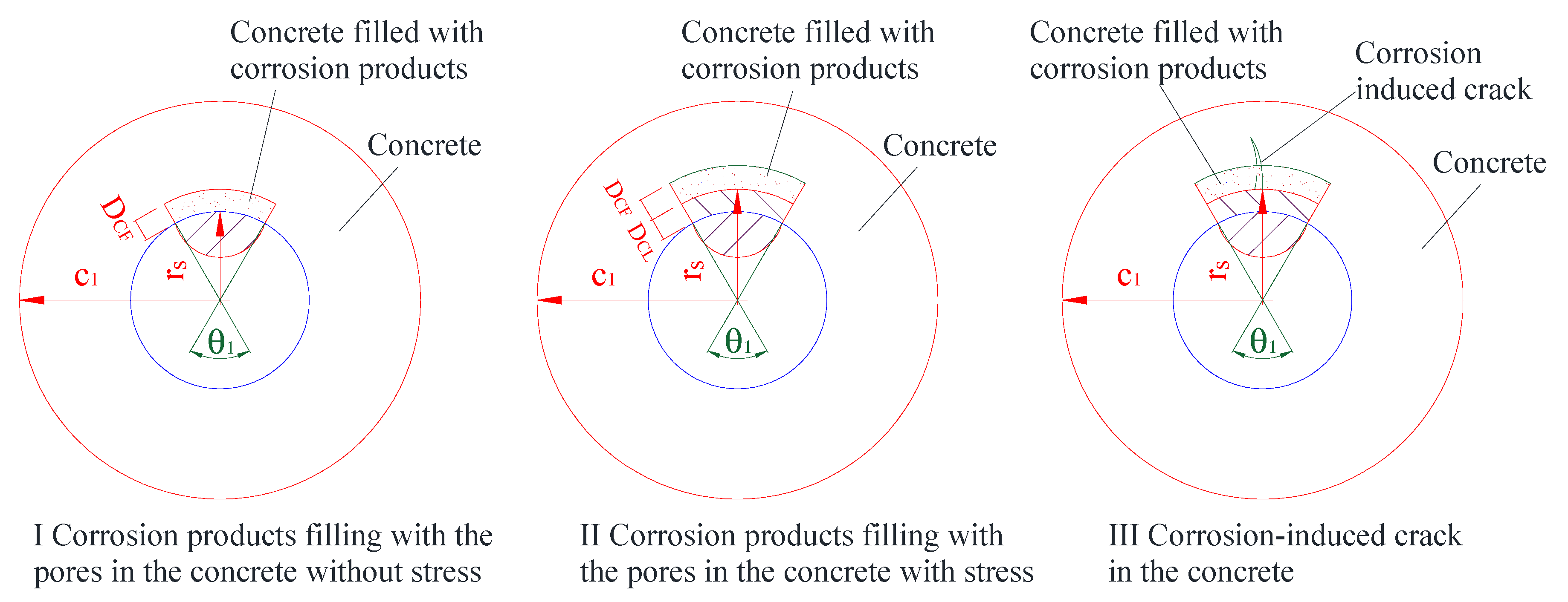
2.2. Corrosion Products Filled into the Pores of Concrete without Stress (Stage I)
2.3. Expansive Stress of the Concrete Cover Induced by the Corrosion Products (Stage II)
2.4. Cracking of the Concrete Cover Induced by the Corrosion Products (Stage III)
3. Model Validation
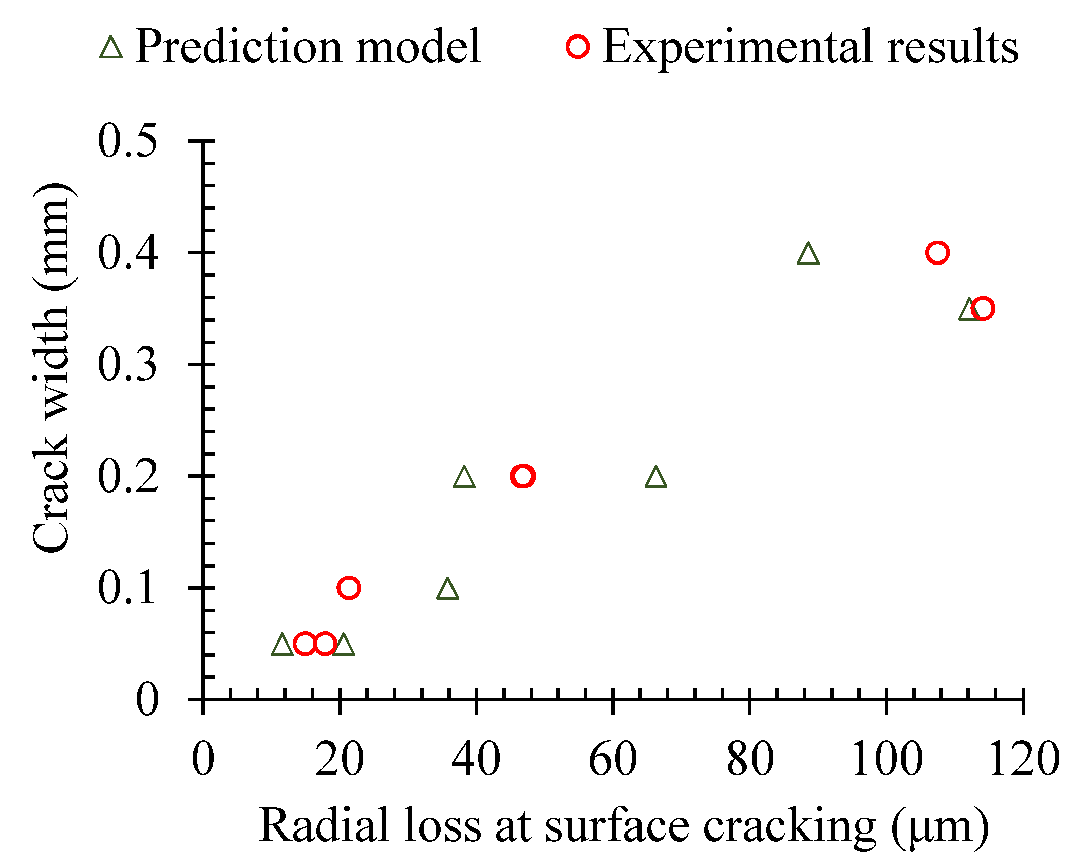
3.1. Corrosion of the Steel Reinforcement Corresponding to the Cracking of the Concrete Cover
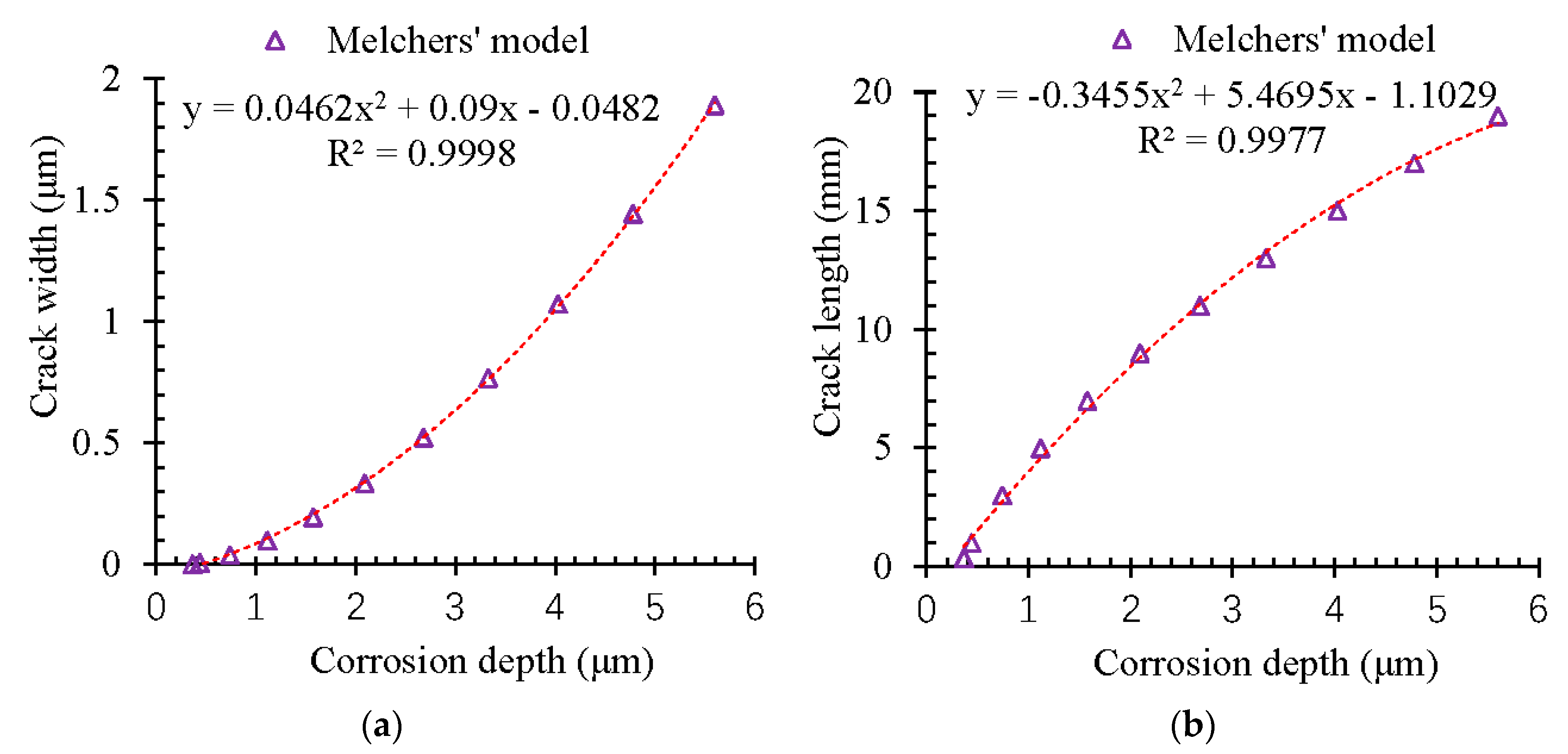
3.2. Influence of Corrosion on the Propagation of the Cracking Path
4. Discussion
4.1. Compression Induced by the Corrosion of Steel Reinforcement
4.2. Radial Displacement of the Concrete in the Steel-Concrete Interface
4.3. Propagation of the Inner Cracking
5. Conclusions
- (1)
- A new predicted model about the cracking propagation of the concrete cover induced by the non-uniform corrosion of the steel reinforcement was proposed based on Melchers’ model and the thick cylinder theory. The predicted results were validated by the experimental results.
- (2)
- The corrosion compression to the concrete was increased in a linear way at first. However, the appearance of the corrosion-induced cracks could release the compression significantly, even though the value was far smaller than the ultimate stress.
- (3)
- With the propagation of the corrosion, the width and the length of the corrosion-induced crack were developed in a non-linear way in the concrete cover. The pitting depth of 6 μm would lead to an inner crack with a length of 20 mm and a width of about 2 μm in the concrete cover.
Author Contributions
Funding
Conflicts of Interest
Abbreviations
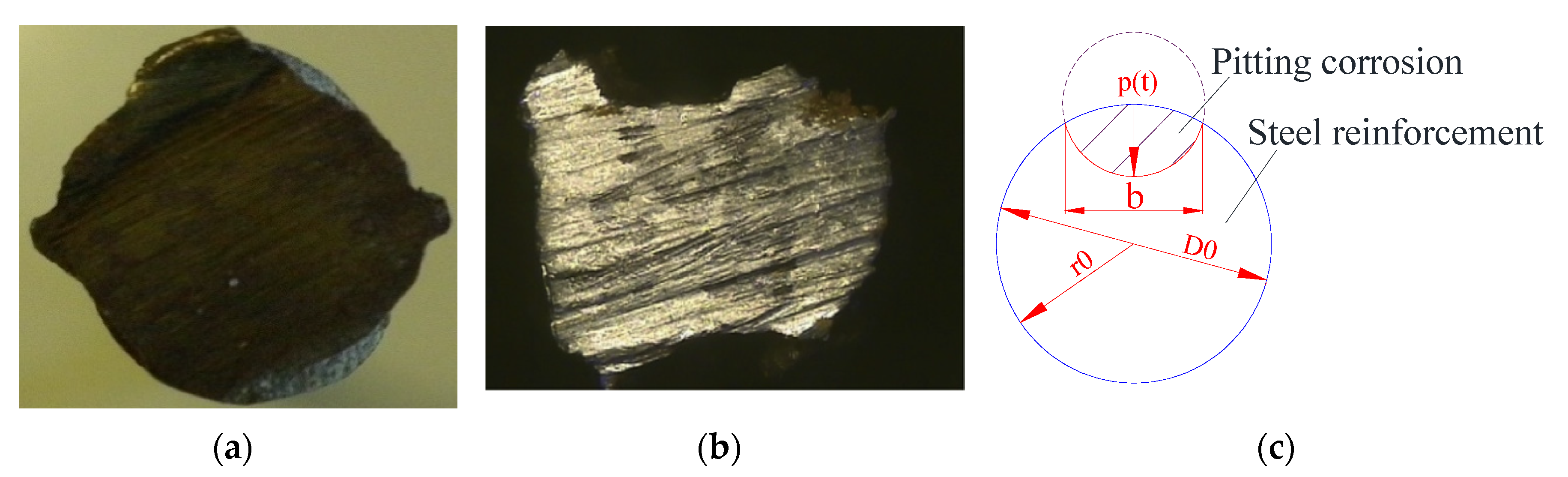
| cross-sectional loss of the pitting corrosion; | |
| radius of the origin steel reinforcement without corrosion; | |
| maximum depth of the pitting corrosion; | |
| DCL | depth of corrosion layer; |
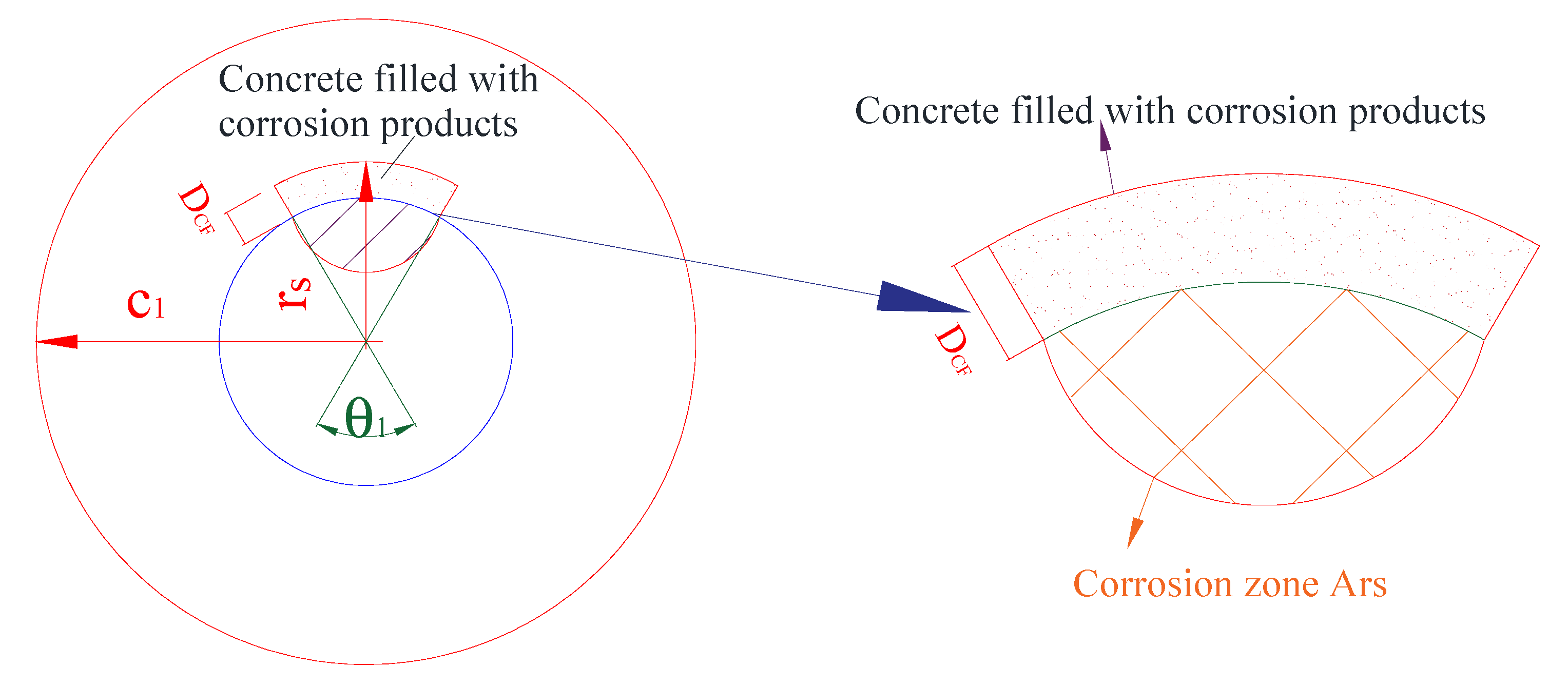
| DCF | depth of concrete cover filled with the corrosion products; |
| maximum value of DCF; | |
| threshold thickness of corrosion layer; | |
| equivalent depth of the concrete cover; | |
| capillary porosity of cementitious matrix of the concrete cover; | |
| internal radius of the cylinder; | |
| central angle corresponding to the corrosion zone around the steel reinforcement; | |
| w/c | ratio of water to cement; |
| Acp | area of corrosion products; |
| volumetric expansion factor of the corrosion products; | |
| tension strain of the concrete induced by the corrosion products; | |
| pcorr | corrosion pressure induced by the corrosion products; |
| corrosion pressure in the concrete at the radius rs along the radius direction; | |
| hoop stress at the radius rs; | |
| c1 | external radius of the cylinder; |
| Young’s modulus of concrete; | |
| cracked section of the concrete cover; | |
| non-cracked section of the concrete cover; | |
| elastic stress of the concrete cover with inner crack; | |
| peak tensile stress of the concrete; | |
| critical radius corresponding to the internal radius of the non-cracked cylinder. | |
| hoop stress at a generic radius r; | |
| a, b | coordinates of the intersection point of the two softening lines; |
| w | width of the corrosion-induced crack; |
| peak of the corrosion-induced crack corresponding to zero tensile strength; | |
| total elongation of the concrete cover; | |
| n | number of corrosion cracks; |
| width of the corrosion-induced crack; | |
| average value of the corrosion-induced crack; | |
| deformation of the concrete induced by the corrosion products; | |
| ratio of the crack area filled with the corrosion products; | |
| ratio of hook stress and the radial stress; |
References
- Hay, R.; Ostertag, C.P. Influence of transverse cracks and interfacial damage on corrosion of steel in concrete with and without fiber hybridization. Corros. Sci. 2019, 153, 213–224. [Google Scholar] [CrossRef]
- Zhu, W.J.; François, R. Structural performance of RC beams corroded in chloride environment for a long period. Mater. Struct. 2015, 48, 1757–1769. [Google Scholar] [CrossRef]
- Angst, U.M. Challenges and opportunities in corrosion of steel in concrete. Mater. Struct. 2018, 51, 4. [Google Scholar] [CrossRef] [Green Version]
- Zhu, W.J.; François, R. Influence of long-term chloride diffusion in concrete and the resulting corrosion of reinforcement on the serviceability of RC beams. Cem. Concr. Compos. 2016, 71, 144–152. [Google Scholar] [CrossRef]
- Guo, Z.Z.; Ma, Y.F.; Wang, L.; Zhang, J.R.; Harik, I.E. Corrosion fatigue crack propagation mechanism of high strength steel bar in various environments. J. Mater. Civ. Eng. 2019. [Google Scholar] [CrossRef]
- Marcotte, T.D.; Hansson, C.M. Corrosion products that form on steel within cement paste. Mater. Struct. 2007, 40, 325–340. [Google Scholar] [CrossRef]
- Jung, M.S.; Kim, K.B.; Lee, S.A.; Ann, K.Y. Risk of chloride-induced corrosion of steel in SF concrete exposed to a chloride-bearing environment. Constr. Build. Mater. 2018, 166, 413–422. [Google Scholar] [CrossRef]
- Zhu, W.J.; François, R. Propagation of corrosion-induced cracks of the RC beam exposed to marine environment under sustained load for a period of 26 years. Cem. Concr. Res. 2018, 103, 66–76. [Google Scholar] [CrossRef]
- Liu, Y.P.; Weyers, R.E. Modeling the time-to-corrosion cracking in chloride contaminated reinforced concrete structures. ACI Mater. J. 1998, 96, 675–681. [Google Scholar]
- Zhu, W.J.; François, R.; Poon, C.S.; Dai, J.G. Influences of corrosion degree and corrosion morphology on the ductility of steel reinforcement. Constr. Build. Mater. 2017, 148, 297–306. [Google Scholar] [CrossRef]
- Michel, A.; Pease, B.J.; Geiker, M.R.; Dai, J.G. Monitoring reinforcement corrosion and corrosion-induced cracking using non-destructive x-ray attenuation measurements. Cem. Concr. Res. 2011, 41, 1085–1094. [Google Scholar] [CrossRef]
- Wong, H.S.; Zhao, Y.X.; Karimi, A.R.; Buenfeld, N.R.; Jin, W.L. On the penetration of corrosion products from reinforcing steel into concrete due to chloride-induced corrosin. Corros. Sci. 2010, 52, 2469–2480. [Google Scholar] [CrossRef] [Green Version]
- Chitty, W.J.; Dillmann, P.; Hostis, V.L.; Lombard, C. Long-term corrosion resistance of metallic reinforcements in concrete–a study of corrosion mechanisms based on archaeological artifacts. Corros. Sci. 2005, 47, 1555–1581. [Google Scholar] [CrossRef]
- Zhu, W.J.; François, R.; Coronelli, D.; Cleland, D. Effect of corrosion of reinforcement on the mechanical behaviour of highly corroded RC beams. Eng. Struct. 2013, 56, 544–554. [Google Scholar] [CrossRef]
- Cui, Z.; Alipour, A. Concrete cover cracking and service life prediction of reinforced concrete structures in corrosive environments. Constr. Build. Mater. 2018, 159, 652–671. [Google Scholar] [CrossRef]
- Zhu, W.J.; Dai, J.G.; Poon, C.S. Prediction of the bond strength between non-uniformly corroded steel reinforcement and deteriorated concrete. Constr. Build. Mater. 2018, 187, 1267–1276. [Google Scholar] [CrossRef]
- Chernin, J.; Val, D.V.; Volokh, K.Y. Analytical modelling of concrete cover cracking caused by corrosion of reinforcement. Mater. Struct. 2010, 43, 543–556. [Google Scholar] [CrossRef]
- Lu, C.H.; Jin, W.L.; Liu, R.G. Reinforcement corrosion-induced cover cracking and its time prediction for reinforced concrete structures. Corros. Sci. 2011, 53, 1337–1347. [Google Scholar] [CrossRef]
- Zhu, W.J.; François, R.; Coronelli, D.; Coronelli, D. Failure mode transitions of corroded deep beams exposed to marine environment for long period. Eng. Struct. 2015, 96, 66–77. [Google Scholar] [CrossRef]
- Michel, A.; Pease, B.J.; Peterová, A.; Geiker, M.R.; Stang, H.; Thybo, A.E.A. Penetration of corrosion products and corrosion-induced cracking in reinforced cementitious materials: Experimental investigations and numerical simulations. Cem. Concr. Compos. 2014, 47, 75–86. [Google Scholar] [CrossRef]
- Timoshenko, S.P.; Goodier, J.N. Theory of Elasticity; McGraw Hill Book Co.: New York, NY, USA, 2007. [Google Scholar]
- Zhu, W.J.; François, R. Corrosion of the reinforcement and its influence on the residual structural performance of a 26-year-old corroded RC beam. Constr. Build. Mater. 2014, 51, 461–472. [Google Scholar] [CrossRef]
- Zhu, W.J.; François, R.; Liu, Y. Propagation of corrosion and corrosion patterns of bars embedded in RC beams stored in chloride environment for various periods. Constr. Build. Mater. 2017, 145, 147–156. [Google Scholar] [CrossRef]
- Val, D.V.; Melchers, R.E. Reliability of deteriorating RC slab bridges. J. Struct. Eng. 1997, 123, 1638–1644. [Google Scholar] [CrossRef]
- Coccia, S.; Imperatore, S.; Rinaldi, Z. Influence of corrosion on the bond strength of steel rebars in concrete. Mater. Struct. 2016, 49, 537–551. [Google Scholar] [CrossRef]
- Zhao, Y.X.; Dong, J.F.; Wu, Y.Y.; Jin, W. Corrosion-induced concrete cracking model considering corrosion product-filled paste at the concrete/steel interface. Constr. Build. Mater. 2016, 116, 273–280. [Google Scholar] [CrossRef]
- Tepfers, R. Cracking of concrete cover along anchored deformed reinforcing bars. Mag. Concr. Res. 1979, 31, 3–12. [Google Scholar] [CrossRef]
- Den, U.J.A.; Bigaj, A.J. A bond model for ribbed bars based on concrete confinement. HERON 1996, 41, 206–226. [Google Scholar]
- Van der Veen, C. Theoretical and experimental determination of the crack width in reinforced concrete at very low temperatures. HERON 1990, 35, 111. [Google Scholar]
- Bazant, Z.P. Concrete fracture models: Testing and practice. Eng. Fract. Mech. 2002, 69, 165–205. [Google Scholar] [CrossRef]
- Yu, L.; François, R.; Gagné, R. Influence of steel–concrete interface defects induced by top-casting on development of chloride-induced corrosion in RC beams under sustained loading. Mater. Struct. 2016, 49, 5169–5181. [Google Scholar] [CrossRef]
- Bossio, A.; Monetta, T.; Bellucci, F.; Lignola, G.P.; Prota, A. Modeling of concrete cracking due to corrosion process of reinforcement bars. Cem. Concr. Res. 2015, 71, 78–92. [Google Scholar] [CrossRef]
- Zhu, W.J.; François, R. Experimental investigation of the relationships between residual cross-section shapes and the ductility of corroded bars. Constr. Build. Mater. 2014, 69, 335–345. [Google Scholar] [CrossRef]
- Yu, K.Q.; Zhu, W.J.; Ding, Y.; Lu, Z.D.; Yu, J.T.; Xiao, J.Z. Micro-structural and mechanical properties of ultra-high performance engineered cementitious composites (UHP-ECC) incorporation of recycled fine powder (RFP). Cem. Concr. Res. 2019, 124, 105813. [Google Scholar]
- Andrade, C.; Alonso, C.; Molina, F.J. Cover cracking as a function of bar corrosion: Part 1-Experimental test. Mater. Struct. 1993, 26, 453–464. [Google Scholar] [CrossRef]
- Vu, K.; Stewart, M.G.; Mullard, J. Corrosion-induced cracking: Experimental data and predictive models. ACI Struct. J. 2009, 106, 719–726. [Google Scholar]


© 2020 by the authors. Licensee MDPI, Basel, Switzerland. This article is an open access article distributed under the terms and conditions of the Creative Commons Attribution (CC BY) license (http://creativecommons.org/licenses/by/4.0/).
Share and Cite
ZHU, W.; YU, K.; XU, Y.; ZHANG, K.; CAI, X. A Prediction Model of the Concrete Cracking Induced by the Non-Uniform Corrosion of the Steel Reinforcement. Materials 2020, 13, 830. https://doi.org/10.3390/ma13040830
ZHU W, YU K, XU Y, ZHANG K, CAI X. A Prediction Model of the Concrete Cracking Induced by the Non-Uniform Corrosion of the Steel Reinforcement. Materials. 2020; 13(4):830. https://doi.org/10.3390/ma13040830
Chicago/Turabian StyleZHU, Wenjun, Kequan YU, Yude XU, Kai ZHANG, and Xiaopei CAI. 2020. "A Prediction Model of the Concrete Cracking Induced by the Non-Uniform Corrosion of the Steel Reinforcement" Materials 13, no. 4: 830. https://doi.org/10.3390/ma13040830