Abstract
TC11 alloy is a promising structural material, and has a wide range of applications in many corrosive and high temperature hydrothermal systems. The passive film has an important influence on its electrochemical behavior. In this study, in-situ electrochemical methods (that is, open circuit potential (OCP), linear polarization (LP) and electrochemical impedance spectroscopy (EIS)) were used to monitor the long period electrochemical behavior of TC11 alloy in 0.01 M Na2SO4 solution at 300 °C/10 MPa. The growth kinetics of the passive film was mainly studied. The correlation between the evolution of the electrochemical behavior and the growth of the oxide film was discussed. The results showed that although the OCP gradually stabilized after twenty thousand seconds, henceforth the polarization resistance (Rp) was still increasing due to the thickening of the passive film. An equivalent circuit was proposed to fit the EIS experimental data, leading to determination of film capacitance and film resistance. Besides, the electrochemical data was interpreted in terms of the point defect model (PDM). The EIS results are consistent with the Rp results.
1. Introduction
As a promising structural material, titanium and titanium alloys are widely used in many fields [1]. Titanium materials can be used in aerospace, marine, automobile industry, chemical industry and biomedical field, because of their excellent corrosion resistance and mechanical properties [2,3,4,5,6,7,8]. One of the reasons for the widespread application of titanium materials is the protective effect of the compact oxide film generated on their surface [9,10]. However, they are still unavoidably subject to corrosion under extreme conditions, such as corrosive high temperature aqueous solutions. The corrosion status of the alloy is closely related to the properties of the surface passive film. Therefore, an investigation about the properties of passive film on the alloys surface can contribute to understand the corrosion behavior of these alloys [11].
TC11 alloy is often used as a structure material for high temperature aggressive aqueous environments, due to its excellent corrosion resistance. TC11 is a suitable material for many hydrometallurgical applications and structural materials for nuclear power plants, as well as for containers for disposal of nuclear fuel wastes. Sulfate is often found in these applications. In addition, a typical temperature of 300 °C is often experienced in many industrial processes, such as nuclear power plant systems, supercritical water oxidation (SCWO) systems, and high pressure acid leaching (HPAL) processes. The purpose of our study is to evaluate the corrosion behavior of the TC11 alloy under high temperature and pressure.
Our previous researches focused on the electrochemical corrosion behavior of the TC11 alloy at the initial stage of immersion in the presence of sodium sulfate [12,13]. The effects of temperature, pressure and component concentration on the corrosion behavior of this TC11 alloy were investigated [12]. Besides, the electrical properties of the oxide film formed by potentiostatic anodization was also studied [13]. It is also meaningful to monitor the behavior when alloy is immersed in solutions for a long time, because it may have electrochemical characteristics that differ from short-time immersion behavior [14].
The film growth kinetics controls the electrochemical behavior variation with time of the facile passive alloy [14]. The aim of our present research is an evaluation of the long-term behavior of TC11 at high temperature and pressure solutions in the presence of a sulfate ion. Its electrochemical response during long time immersion is also dominated by the growth kinetics of the oxide film. There have been many studies on growth kinetics of oxide film on alloy surface [14,15,16,17,18,19,20], and they concluded that the electrochemical characteristics varied over time, especially in the initial stage of immersion. Although the high field model (HFM) is initially adopted widely [21,22], it cannot comprehensively interpret the features of oxide film growth, and it does not involve the problem of stable state thickness [23]. Based upon HFM, a modified model is proposed considering the dissolution [24] and transport behavior occurring at the film/solution interface [25]. Subsequently, the PDM gradually developed and became a common model to deal with the long time growth behavior of oxide film [14,26,27,28,29]. Many researchers used the PDM to evaluate the property variation of passive films formed on iron [30,31], copper [32], stainless steel [33,34,35,36] and nickel alloys [37,38]. However, there are few studies on the properties of passive films formed on titanium alloys. In particular, the long-time electrochemical behavior changes caused by the growth of passive film is a significant issue.
In this present work, the growth kinetics of a native oxide film of TC11 in Na2SO4 solution in the temperature of 300 °C and pressure of 10 MPa was investigated by a variety of electrochemical techniques, that is, open circuit potential (OCP), linear polarization (LP) and electrochemical impedance spectra (EIS). The effect of the immersion period on the film thickness, film resistance and polarization resistance of the oxide film was studied. The PDM was employed to model EIS data to evaluate the passive film evolution within the immersion time. The related growth mechanisms of the oxide film were also discussed.
2. Materials and Methods
TC11 alloy (Baoti, Baoji, China) was used as the specimen material, and its nominal composition (wt %) is 6.5% Al, 3.5% Mo, 1.5% Zr, 0.3% Si and Bal. Ti. The specimens were fabricated from TC11 rods of a 10 mm diameter. All samples were ground to 1500 grit using SiC papers. The testing solution was 0.01 M Na2SO4 prepared with analytically pure sodium sulfate (Aladdin, Shanghai, China) and ultrapure water (Institute of Geochemistry, Guiyang, China). High purity argon was used to remove oxygen from the system.
All electrochemical measurements were performed in a multifunctional autoclave (Institute of Geochemistry, Guiyang, China) equipped with a three electrodes system. The temperature and pressure of the experiments were maintained at 300 °C and 10 MPa, respectively. The counter electrode was a self-made alumina ceramic cone frustum with a platinum wire inside, and platinum paste was sintered on the surface of the ceramic to achieve enough counter electrode surface area. The reference electrode is an external pressure-balanced Ag/AgCl electrode, filled with 0.1 M KCl as an internal reference solution. The reference electrode was placed at room temperature (25 °C) and maintained at system pressure via the Luggin capillary. The thermal diffusion potential problem can be solved based on the work of Macdonald [39].
In the present work, the calibrated equation of the electrode potential is shown as follows:
where ΔEobs is the observed potential of the working electrode vs. the Ag/AgCl external reference electrode, and ΔESHE is the converted potential vs. the standard hydrogen electrode (SHE) at the experimental temperature, ΔT = T − 298.5 K, T is the experimental temperature in K. All the potential values in the text are relative to the SHE except for special mention.
A Princeton applied research (PAR) 2263 electrochemical workstation (AMETEK, San Diego, CA, USA) was used to perform the electrochemical tests. The long-term OCP measurements were performed for 36 h. The potentiodynamic polarization experiment was conducted from −0.3 V vs. OCP to 1.6 V vs. SHE with a scanning rate of 2 mV/s. The EIS were measured using an excitation signal of 10 mV in amplitude in the frequency from 10−2 to 105 Hz at OCP. The EIS data were analyzed by a Zsimpwin (3.10) software (AMETEK, San Diego, CA, USA). The polarization resistance measurements were conducted from −20 mV to +20 mV vs. OCP with a scan rate of 0.167 mV/s. All of the electrochemical measurements mentioned above were performed at different immersion time intervals.
3. Results and Discussion
To clear up the evolution of native passive film on TC11 over time, we successively carried out a series of experiments to investigate the variation of the electrochemical status at the electrode surface. EIS combined with LP tests were conducted at certain time intervals during the long-term (36 h) OCP test. Applying a small excitation potential to the electrode will do so in a way that almost does not affect the surface state of the electrode. Hence, we have reason to believe that the mentioned tests will not affect the totality tendency of the long term OCP measurements [14].
3.1. Long-Term OCP Tests
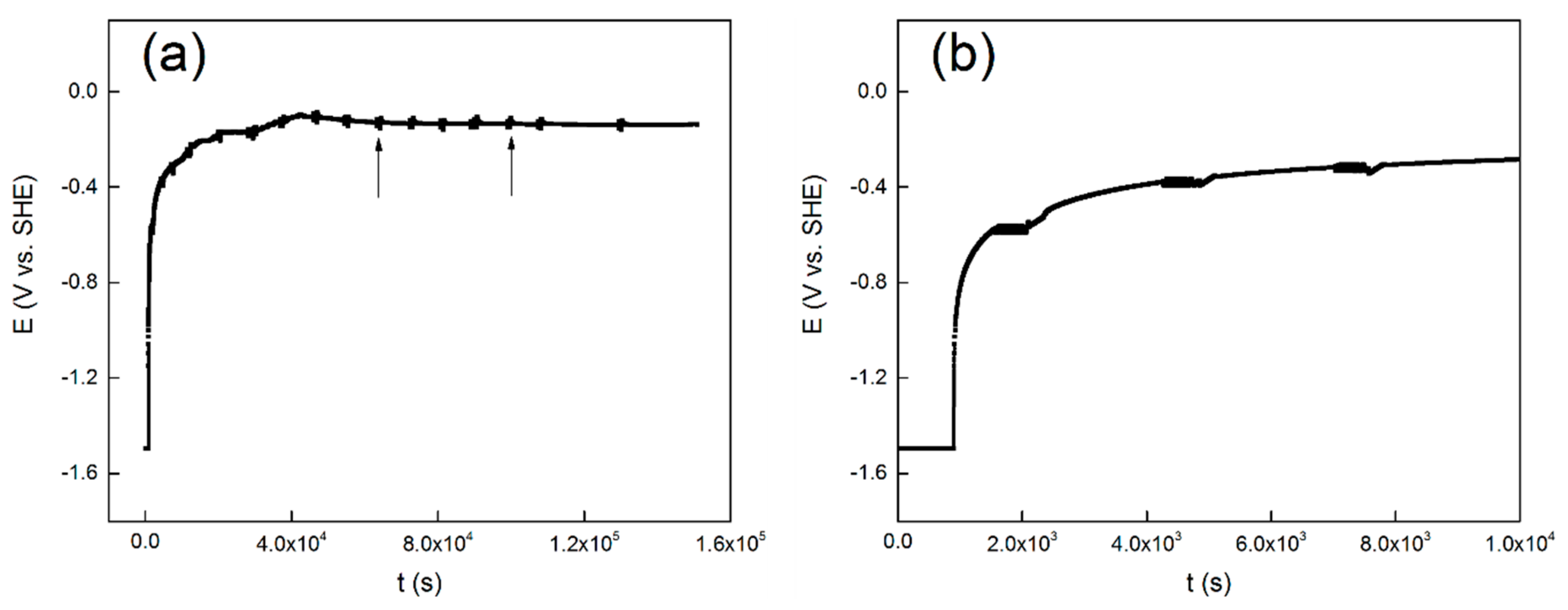
The evolution of OCP over time is shown in Figure 1a, and the first ten thousand seconds are presented in Figure 1b. Similar evolution of open circuit potential with time was reported for commercial pure titanium [40], Ti-6Al-4V [41] and 304 stainless steel [42]. It shows in Figure 1a that the potential exhibits a rapid shift at the initial stage of the measurement. It also shows in Figure 1a, that at about twenty thousand seconds, the OCP values gradually stabilizes and reaches a steady-state value of −0.15 V. The first ten thousand seconds of the measurement is shown in Figure 1b to get a better view. The black arrows indicate the location of the LP tests and the EIS tests.
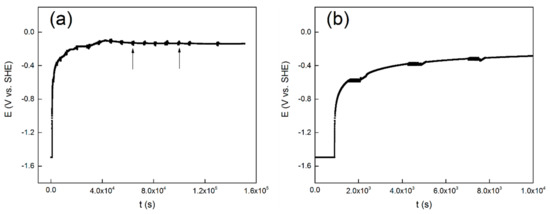
Figure 1.
Evolution of open circuit potential with time for the TC11 alloy in 0.01 M Na2SO4 solution, (a) the total 36 h, and (b) the first 10 ks.
It starts with the first cathodic reduction procedure at −1.5 V vs. SHE. Based on the Pourbaix diagram of titanium at 300 °C [43], the metal titanium phase is in a thermodynamic stable state when the pH of the aqueous solution is close to neutral and the potential is −1.5 V vs. SHE. Therefore, a cathodic potentiostatic reduction at −1.5 V vs. SHE for 15 min is believed to partly remove the oxide film formed by air oxidation on the surface of the alloy electrode. Though it is thermodynamically feasible to reduce the oxide film completely, this is unlikely as a result of the slow reduction rate of TiO2. Nevertheless, the first cathodic reduction procedure is to reproduce the initial surface condition before the OCP test. Then the OCP values increased rapidly in an exponential form. This is attributed to the formation and development of a passive film on the surface [40]. The protective passive film may act as a barrier layer to prevent the release of the metal ion. After this stage, the passive film begins to thicken over time. At last, the OCP gradually reaches a stable value, and the metal/solution interface reaches a stable state.
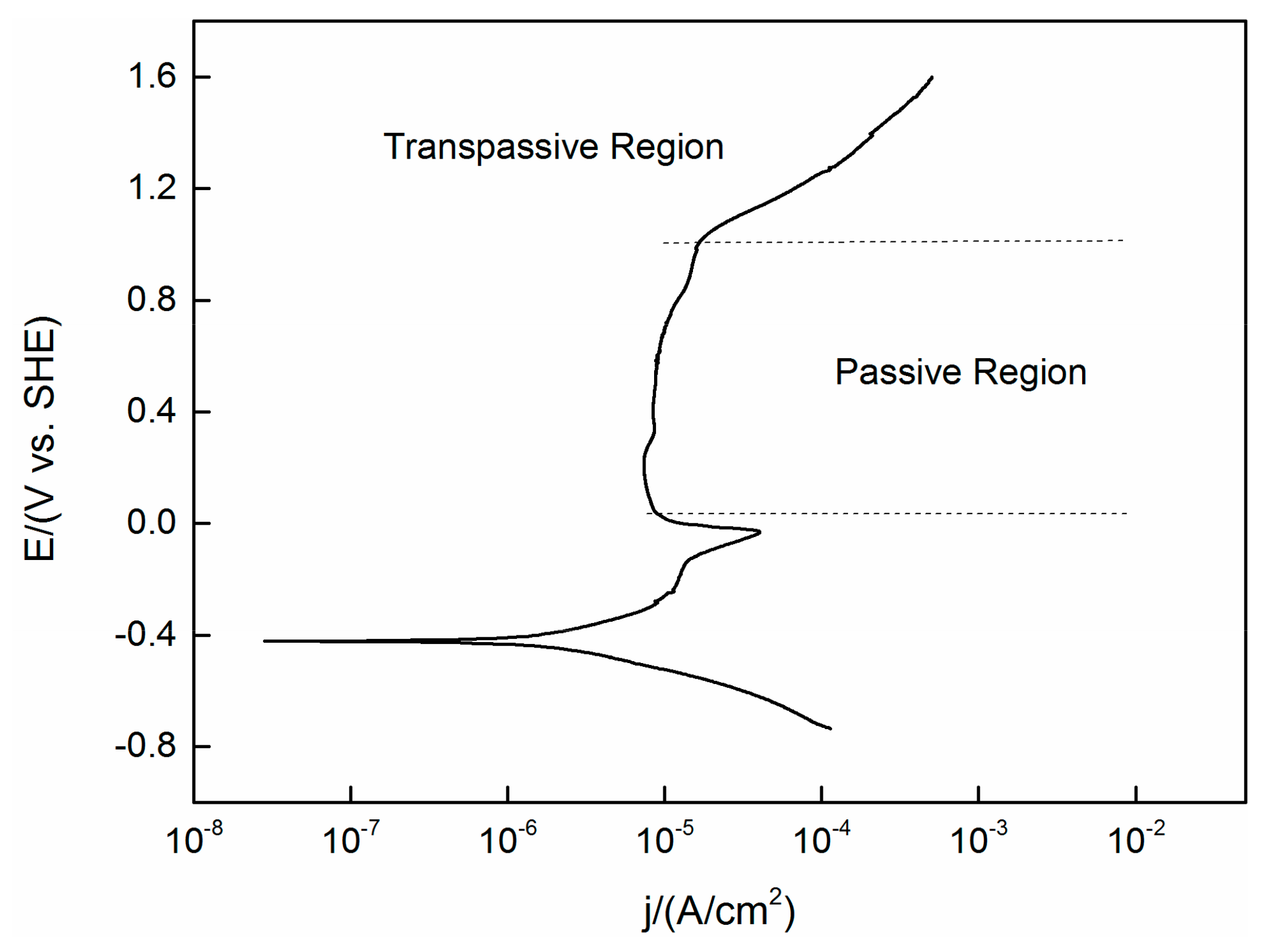
A PDP curve obtained under the same experimental conditions (temperature, pressure and concentration) as the OCP test previously mentioned is shown in Figure 2. The steady state OCP values (as shown in Figure 1) are located in the region not yet reach the passive area of the PDP curve. This means that the active–passive transient state has not yet passed, despite the fact that oxides are expected to be present on the surface, it will not lead to complete passivation of the alloy.
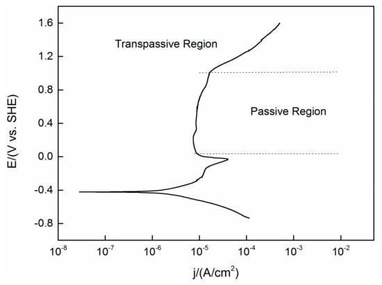
Figure 2.
Polarization curve of TC11 alloy in 0.01 M Na2SO4. Scan in positive direction at 2 mV/s.
3.2. Polarization Resistance
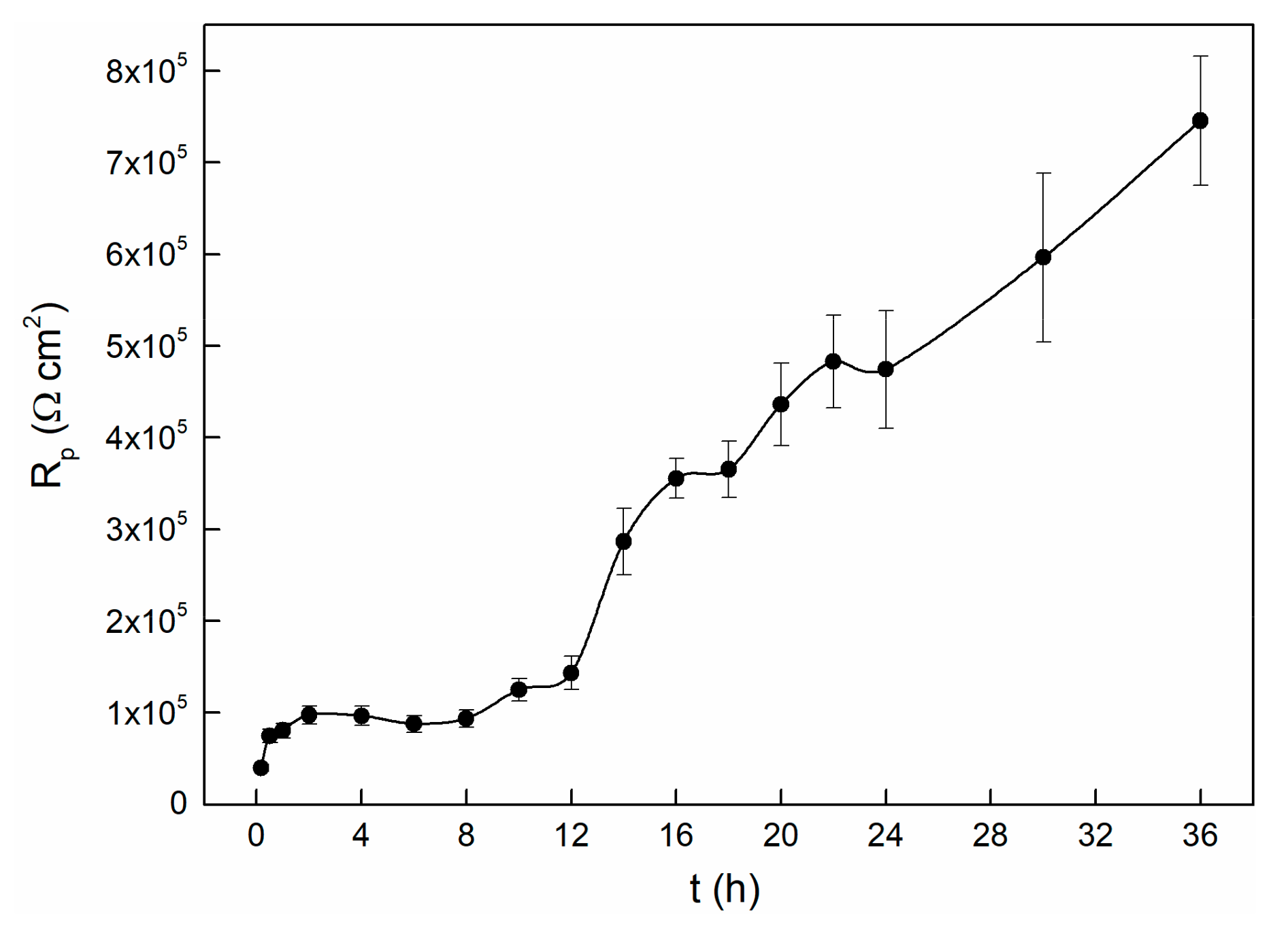
In the process of the OCP experiment, LP tests were carried out to characterize the passivation state of the alloy [42]. The evolution of the polarization resistance over time is shown in Figure 3. The varying curve can be divided into three stages. It seems that the Rp values increase with time in the initial two hours. After that, the Rp values remain stable for about six hours, followed by increasing very sharply in the remaining tests. This indicates that during this period, the electrode surface is undergoing transition from the activated state to the passivation state, and we thus observed a remarkable increase of polarization resistance [14]. It is interesting to note that although the OCP value is stable after approximately twenty thousand seconds (as shown in Figure 1), the value of Rp raises obviously after this time node. This indicates that even though the potential reaches a stable state within twenty thousand seconds, the entire interface processes are still in progress, and it changes the passive state. Similarly, the polarization resistance dependence of time of 304 stainless steel also shows this kind of variety. The OCP begins to stabilize at about 15 ks, while the Rp starts to become stable at about 30 ks. They attributed this to the interface reactions that keep on influencing the structure of the passive film, even though the OCP has reached a steady state [42].
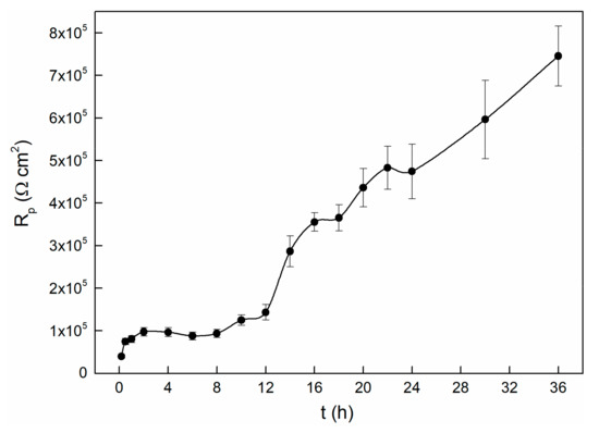
Figure 3.
Polarization resistance changes with time for TC11 alloy in 0.01 M Na2SO4 solution.
Herein, it is roughly assumed that after twenty thousand seconds, the interface state between the solution and film will keep stable, and therefore the OCP value almost changes no more. Thus, the increases in Rp value maybe caused by thickening of the passivation film as time prolongs. This speculation can be further verified by EIS because it can obtain more kinetics information and electrode interface structure information.
3.3. Electrochemical Impedance Spectroscopy
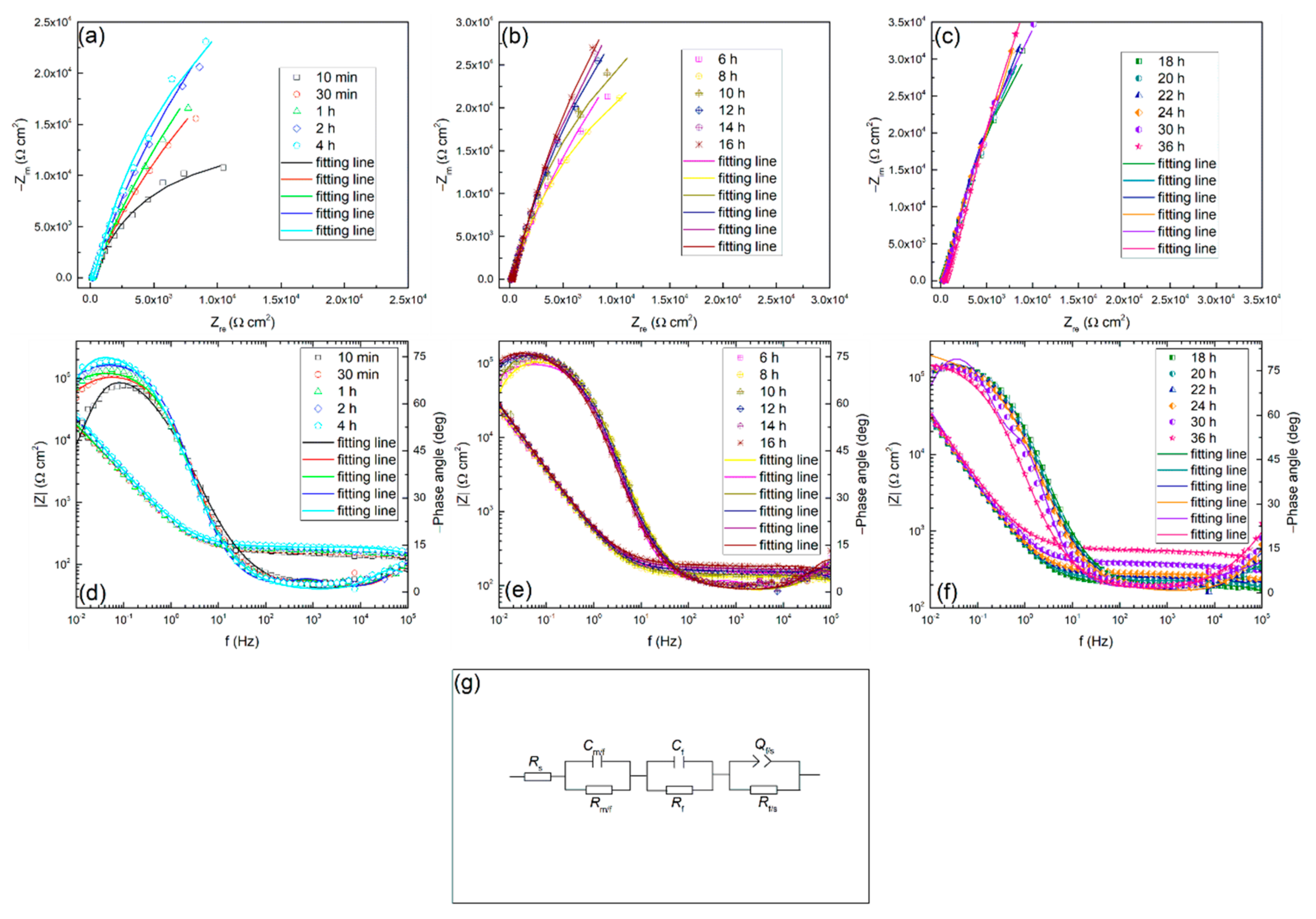
EIS measurements were also conducted and the relevant Nyquist and Bode plots at different times in 0.01 M Na2SO4 solution are shown in Figure 4. It can be found that all the spectra have a similar shape, which means the same growth mechanism of the passive film at different times during the test. Besides, the semicircular arc of the impedance spectrum changes with time. In the first two hours, the impedance magnitude increases rapidly, then it shows a moderate growth in the next six hours, and then increases continuously with time. The appearance of such a tendency also indicates that the passive state of the alloy surface is changing with time. This is possibly attributed to the growth of oxide film, and it may control the general interface behavior. The above results are coincident with the experimental results of the polarization resistance.
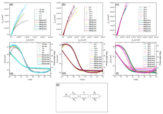
Figure 4.
Nyquist (a), (b), (c), Bode (d), (e), (f) plots for TC11 alloy in 0.01 M Na2SO4 solution as a function of immersion time, and (g) electrical equivalent circuit used to fit the electrochemical impedance spectroscopy (EIS) data.
3.3.1. EIS Analysis Using Equivalent Circuit
EIS is a very important method in electrochemical measurement technology. It is an important means to study the kinetics of electrode process, and can provide comprehensive information of interface state and process.
In the current study, the EIS as a function of time of TC11 was continuously measured to understand the growth behavior of the surface passive film. An equivalent circuit is usually used to fit impedance spectrum data to interpret the growth behavior more comprehensively. The EIS data was fitted using a circuit with the circuit description code (CDC) expressed as Rs (Rm/f Cm/f) (Rf Cf) (Rf/s Qf/s), which is also presented in Figure 4. Where, R, C and Q represents resistance, capacitance and constant phase element (CPE), respectively. Besides, the subscripts m, f and s refer to metal, passive film and solution, respectively. Priyantha [44] and Nickchi [14,45] used the same circuit in their work. In this work, Rs means solution resistance, parallel connection combination of Rm/f and Cm/f represents the processes occurring between metal and film interface, Rf and Cf represents capacitance and resistance of the passive film and (Rf/s Qf/s) represents processes taking place between the film and solution interface. The fitting results obtained by using the above circuit are shown in Table 1.

Table 1.
The EIS fitting parameters obtained by using the equivalent circuit for TC11 alloy in 0.01 M Na2SO4 solution.
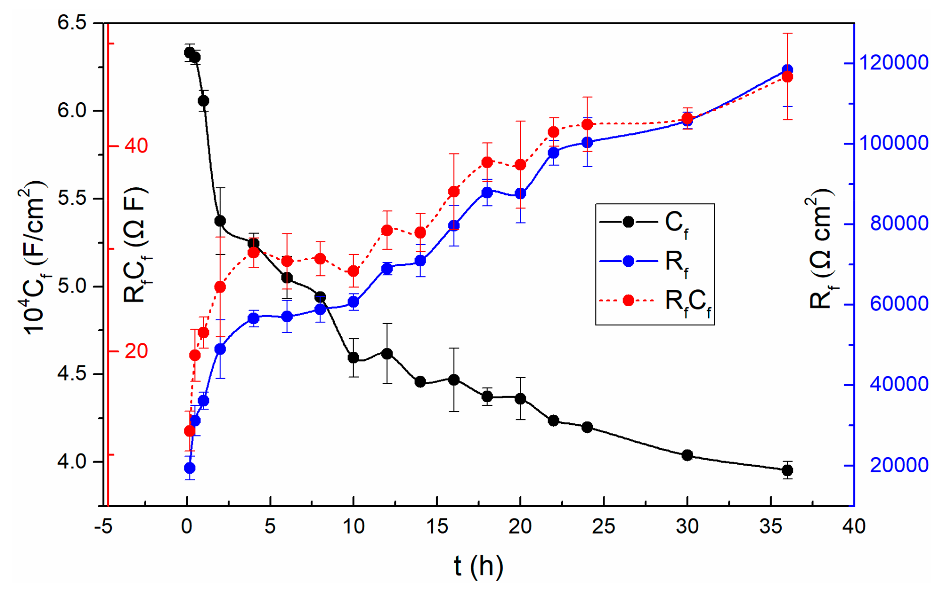
A lower magnitude fitting error of 10−4 indicates that the selected circuit is reasonable [2]. The fitting results show that the solution resistances (Rs) do not change much with time. The Rs fluctuating around 50 Ω·cm2 is due to the solution concentration does not change over time. It is worth noting that the resistance (Rm/f) of the metal/film interface is basically not affected by time until 20 h. So does the corresponding Cm/f. From 20 h to 36 h, the Rm/f increases while the corresponding Cm/f reduces. However, the resistance (Rf/s) at the film/solution interface fluctuates slightly after twenty thousand seconds, which is consistent with the previous discussion in the polarization resistance section. That is, the state of the film/solution interface is stable. The variation of the parameters, n and Y0 of the Qf/s is related to the roughness and uniformity of the outer layer of the passive film. Based on the PDM [23], the potential drop across the film/solution interface, ϕf/s, is a function of the applied voltage and pH. While the potential drop across the metal/film interface, ϕm/f, is a function of applied voltage, pH, the electric field strength of the film and the film thickness. Both the potential drops ϕf/s and ϕm/f are significant, because the potential changes dominate the kinetics of the reactions that occur at the film/solution interface and at the metal/film interface, respectively [46]. In addition, it can be observed that all of the film resistances (Rf) are much larger than other resistances at corresponding times. It indicates that the film evolution dominates the overall interface process. The values of both Rf and Cf are shown in Figure 5, and so does the product of them.
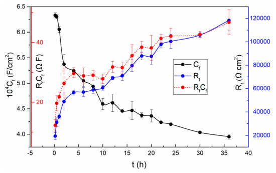
Figure 5.
The variation of Rf, Cf and RfCf with time for TC11 alloy in 0.01 M Na2SO4 solution.
As can be seen from Figure 5, the resistance of the passive film increases significantly at the first stage, and then changes slowly followed by constant increase in the remaining experiments. Since Rf refers to the resistance of the passive film, the increase of Rf implies the increasing thickness of the passive film based on the selected circuit. Remarkably, the vary of Rp value mentioned above is also related to the varying thickness of the passive film. In addition, the decrease of the capacitance (Cf) also proves the increase of the thickness of the film.
The fact that the Cf values become smaller while the Rf values become larger demonstrates that the passive film becomes more and more dense and protective [42].
To find out whether the evolution of Rf and Cf are merely associated with the film thickness, the results of Rf multiplied Cf are also presented in Figure 5. In this case, Equation (4) can be obtained from the following two general Equations (2) and (3):
where, ε is the dielectric constant, ε0 is the permittivity of free space, A refers to area, L is the film thickness. The product of RfCf will be independent of thickness, and is a constant on condition that the chemical and structural characteristics of passivation films do not change with time [14]. However, the obtained result is not steady over time in the sodium sulfate solution. Thus, the change of Cf and Rf is probably not only associated with the film thickness. The above discussions suggest that if the selected equivalent circuit is effective, and accurately represents the physical characteristics of the system, then it is possible that the features of the film will also change with time.
C = (εε0A)/L
R = (ρL)/A
RC = ρεε0
The change in the features of the passive film may be due to the change in the concentration of oxygen vacancy over time [23,47,48,49,50]. The thickness variation of the oxide film involves two reactions: the formation and dissolution of the film [51]. Because the electrode is still in the transition stage from activation to passivation, that is the film is still thickening. This indicates that the kinetics of formation reaction (5) is faster than the dissolution reaction (6) [23].
In this case, it may result in a change in oxygen vacancy concentration with time during the test. Consequently, the relative dielectric constant of the passive film will also increase. However, further research is needed to conduct a deep analysis of the EIS data considering the point defects.
3.3.2. EIS Analysis Using the Point Defect Model
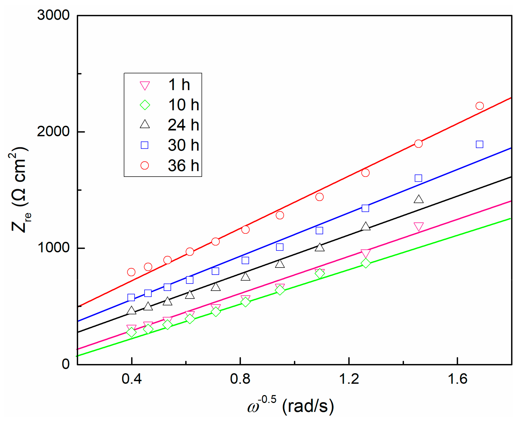
The EIS data was further analyzed using the point defect model (PDM) [52]. The model predicts that the impedance involves point defects transport in the passive film will exhibit in the form of a Warburg impedance. Because the passive film is electrically conductive, electrons can quickly pass through the film. The impedance of both electrons and electron holes can be expressed as a resistance [52], which leads to negligible contributions of both electrons and electron holes to total conductance, thus the total impedance of the interface is also in a Warburg-type impedance. Correspondingly, the total impedance can be simplified to be proportional to ω−1/2. Since no redox species is available in the test solution, that is, no redox reaction occurs at the film/solution interface, this situation is undoubtedly reasonable due to the ionic vacancy carrying a much greater amount of current than the electronic current that generates at the film/solution interface [52]. The relationship between real component Zre and ω−1/2 is shown in Figure 6, and it presents a linear dependence. Consequently, compared with ionic conductivity, the electronic conductivity of the passive film becomes insignificant. It is observed that the Warburg coefficients σ (equal to dZre/dω−1/2) increases with time after 1 h. Based on a previous model [28], assuming the TC11 passive film grows inwardly (namely, it is not precipitated from solution), then the transport of oxygen vacancy dominates the growth of the oxide layer, thus the conductance of the cation vacancies, electrons and electron holes can be ignored. Then the values of the Warburg coefficient [52] are equal to:
where, D refers to diffusivity of oxygen vacancy in the passive film, α refers to the film/solution interface polarizability, and refers to the concentration of oxygen vacancy.
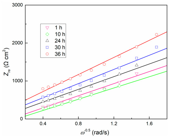
Figure 6.
Dependence of Zre on ω−1/2 for TC11 alloy in 0.01 M Na2SO4 solution.
Diffusion coefficient D is a function of temperature, and α is a fixed value for a certain solution composition [28], resulting in the slope σ only related to the change of concentration of oxygen vacancy . Therefore, it can be inferred that the concentration of oxygen vacancy decreases with time, and thus the internal structure of the passive film becomes more uniform. This is consistent with the prediction of PDM. The product of RfCf mentioned above is also confirmed at this moment.
At last, we investigated the law for the growth kinetics of the passive film. In general, the generation of an oxide film follows a logarithmic law [28], so does the TC11 alloy. In this study, the data is fitted using the logarithmic growth law deduced from the PDM. It is assumed that the electrical field intensity in the passive film is only related to the electrical and chemical characteristics of the film, and then the assumption of a thickness-independent-field strength is also reasonable. Since the transport of oxygen vacancy causes the growth of the film, in that way, according to PDM, the growth kinetics can be calculated by the following equation:
where L refers to film thickness, Ω refers to the molar volume per cation, NV refers to the Avogadro constant and is the flux of oxygen vacancy.
In this case, the thickness of the film can be expressed ultimately in two formulas, depending upon the film thickness, as following [28]:
where, ε is electrical field intensity. It is worth noting that A and B is a function of the external voltage and pH. Because the OCP values have reached steady state, the value of A(B−1) will be a fixed value. For most films, it is reasonable that the thickness is bigger than 5 Å, so the form of logarithmic law was tentatively adopted to reveal the relationship between thickness and time.
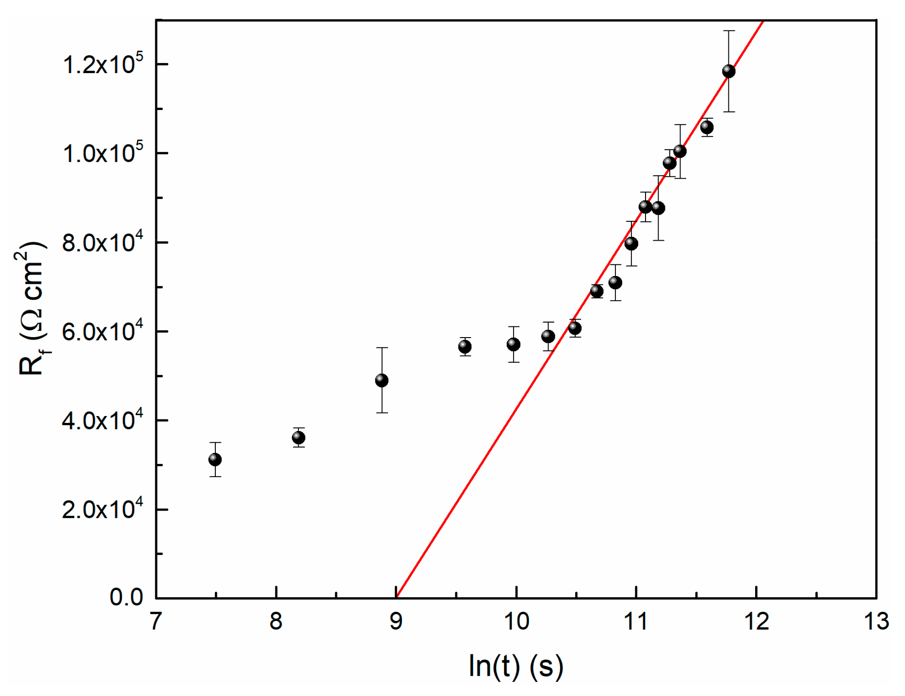
Based on the simulated EIS data in this study and Equation (3), the relationship between Rf and time is shown in Figure 7. It is observed that the Rf data and time could be fitted to logarithmic function, so does the film thickness and time.
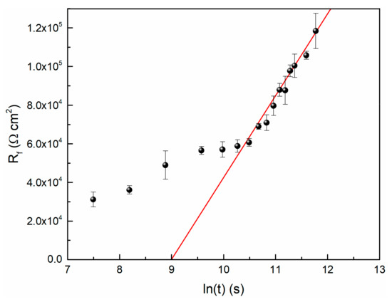
Figure 7.
The logarithmic growth behavior of passive film on TC11 Alloy in 0.01 M Na2SO4.
If it is assumed that the film resistance is a function of its thickness (that is Equation (3)), then the slope of the fitted line can be used to calculate the value of ε. When the value of ρ is 106 Ω·m, the result of ε is equal to 3.09 × 10⁶ V/cm. Generally, the order of magnitude of the electric field strength of passive film is 106 V/cm [11].
4. Conclusions
The long-term electrochemical measurements consisting of OCP, LP and EIS were used to monitor the growth kinetics of passive film on TC11 alloy at 300 °C/10 MPa Na2SO4 solution. The conclusion is as follows:
The electrochemical response of TC11 alloy changes with time, which is dominated by the growth kinetics of the surface passive film. The OCP increases at initial time, and reaches a stable state within twenty thousand seconds; the reason for this change is related to the formation and growth of passive films. The OCP reaches a stable state within twenty thousand seconds, while the Rp value still increases significantly after the same time, indicating the continuous growth of the passive film. The polarization resistance data indicate that the corrosion resistance of the TC11 alloy increases with immersion time. EIS data confirm the overall behavior of Rp. EIS analysis using equivalent circuit indicates that the Rf increases with time while the Cf decreases as time prolong. EIS analysis using the point defect model shows a logarithmic growth law for the film thickness. Film thickness and oxygen vacancy concentration influence the electrochemical response of passive film over time. The electrochemical data are consistent with the prediction of the PDM.
Author Contributions
Resources, N.W.; writing—original draft preparation, L.Z.; writing—review and editing, L.Z.; supervision, H.L.; project administration, H.L. All authors have read and agreed to the published version of the manuscript.
Funding
This research was funded by the National Key Research and Development Plan, grant number 2016YFC0600104 and the ‘‘135” Program of the Institute of Geochemistry, Chinese Academy of Sciences (CAS).
Conflicts of Interest
The authors declare no conflict of interest.
References
- El-Bagoury, N.; Ahmed, S.I.; Abu Ali, O.A.; El-Hadad, S.; Fallatah, A.M.; Mersal, G.A.M.; Ibrahim, M.M.; Wysocka, J.; Ryl, J.; Boukherroub, R.; et al. The influence of microstructure on the passive layer chemistry and corrosion resistance for some titanium-based alloys. Materials 2019, 12, 20. [Google Scholar] [CrossRef]
- De Assis, S.L.; Wolynec, S.; Costa, I. Corrosion characterization of titanium alloys by electrochemical techniques. Electrochim. Acta 2006, 51, 1815–1819. [Google Scholar] [CrossRef]
- Wang, K. The use of titanium for medical applications in the USA. Mater. Sci. Eng. A 1996, 213, 134–137. [Google Scholar] [CrossRef]
- Oberwinkler, B.; Riedler, M.; Eichlseder, W. Importance of local microstructure for damage tolerant light weight design of Ti–6Al–4V forgings. Int. J. Fatigue 2010, 32, 808–814. [Google Scholar] [CrossRef]
- Knobbe, H.; Köster, P.; Christ, H.-J.; Fritzen, C.-P.; Riedler, M. Initiation and propagation of short fatigue cracks in forged Ti6Al4V. Proced. Eng. 2010, 2, 931–940. [Google Scholar] [CrossRef]
- Boyer, R.R. An overview on the use of titanium in the aerospace industry. Mater. Sci. Eng. A 1996, 213, 103–114. [Google Scholar] [CrossRef]
- Jackson, M.; Dring, K. A review of advances in processing and metallurgy of titanium alloys. Mater. Sci. Technol. 2006, 22, 881–887. [Google Scholar] [CrossRef]
- Ansari, G.; Fattah-alhosseini, A. On the passive and semiconducting behavior of severely deformed pure titanium in Ringer’s physiological solution at 37°C: A trial of the point defect model. Mater. Sci. Eng. C 2017, 75, 64–71. [Google Scholar] [CrossRef] [PubMed]
- Fernandez-Domene, R.M.; Blasco-Tamarit, E.; Garcia-Garcia, D.M.; Anton, J.G. Passivity breakdown of titanium in LiBr solutions. J. Electrochem. Soc. 2014, 161, C25–C35. [Google Scholar] [CrossRef]
- Manjaiah, M.; Laubscher, R.F. Effect of anodizing on surface integrity of Grade 4 titanium for biomedical applications. Surf. Coat. Tech. 2017, 310, 263–272. [Google Scholar] [CrossRef]
- Wang, L.; Yu, H.; Wang, S.; Chen, B.; Wang, Y.; Fan, W.; Sun, D. Quantitative analysis of local fine structure on diffusion of point defects in passive film on Ti. Electrochim. Acta 2019, 314, 161–172. [Google Scholar] [CrossRef]
- Zha, L.; Li, H.P.; Wang, N.; Lin, S.; Xu, L.P. Electrochemical corrosion behavior of TC11 alloy in sulfate solution at high temperature and high pressure. Int. J. Electrochem. Sci. 2017, 12, 5704–5722. [Google Scholar] [CrossRef]
- Zha, L.; Li, H.P.; Wang, N. Electrochemical characterization of anodic oxide film on TC11 alloy in sulfate solution at high temperature and high pressure. Int. J. Electrochem. Sci. 2019, 14, 4546–4556. [Google Scholar] [CrossRef]
- Nickchi, T.; Alfantazi, A. Kinetics of passive film growth on Alloy 800 in the presence of hydrogen peroxide. Electrochim. Acta 2011, 58, 743–749. [Google Scholar] [CrossRef]
- Xu, J.; Wu, X.; Han, E.-H. The evolution of electrochemical behaviour and oxide film properties of 304 stainless steel in high temperature aqueous environment. Electrochim. Acta 2012, 71, 219–226. [Google Scholar] [CrossRef]
- De Araújo Figueiredo, C.; Bosch, R.-W.; Vankeerberghen, M. Electrochemical investigation of oxide films formed on nickel alloys 182, 600 and 52 in high temperature water. Electrochim. Acta 2011, 56, 7871–7879. [Google Scholar]
- Bosch, R.W.; Vankeerberghen, M. In-pile electrochemical tests of stainless steel under PWR conditions: Interpretation of electrochemical impedance spectroscopy data. Electrochim. Acta 2007, 52, 7538–7544. [Google Scholar] [CrossRef]
- Macák, J.; Sajdl, P.; Kučera, P.; Novotný, R.; Vošta, J. In situ electrochemical impedance and noise measurements of corroding stainless steel in high temperature water. Electrochim. Acta 2006, 51, 3566–3577. [Google Scholar] [CrossRef]
- Bojinov, M.; Kinnunen, P.; Lundgren, K.; Wikmark, G. A mixed-conduction model for the oxidation of stainless steel in a high-temperature electrolyte. J. Electrochem. Soc. 2005, 152, B250–B261. [Google Scholar] [CrossRef]
- Betova, I.; Bojinov, M.; Kinnunen, P.; Lundgren, K.; Saario, T. Mixed-conduction model for stainless steel in a high-temperature electrolyte: Estimation of Kinetic Parameters of Inner Layer Constituents. J. Electrochem. Soc. 2008, 155, C81–C92. [Google Scholar] [CrossRef]
- Vetter, K.J.; Gorn, F. Kinetics of layer formation and corrosion processes of passive iron in acid solutions. Electrochim. Acta 1973, 18, 321–326. [Google Scholar] [CrossRef]
- Cabrera, N.; Mott, N.F. Theory of the oxidation of metals. Rep. Prog. Phys. 1949, 12, 163–184. [Google Scholar] [CrossRef]
- Macdonald, D.D. The point-defect model for the passive state. J. Electrochem. Soc. 1992, 139, 3434–3449. [Google Scholar] [CrossRef]
- Macdonald, D.D.; Sikora, E.; Sikora, J. The kinetics of growth of the passive film on tungsten in acidic phosphate solutions. Electrochim. Acta 1998, 43, 2851–2861. [Google Scholar] [CrossRef]
- Kirchheim, R. Growth kinetics of passive films. Electrochim. Acta 1987, 32, 1619–1629. [Google Scholar] [CrossRef]
- Macdonald, D.D. The history of the point defect model for the passive state: A brief review of film growth aspects. Electrochim. Acta 2011, 56, 1761–1772. [Google Scholar] [CrossRef]
- Wang, W.; Alfantazi, A. An electrochemical impedance spectroscopy and polarization study of the role of crystallographic orientation on electrochemical behavior of niobium. Electrochim. Acta 2014, 131, 79–88. [Google Scholar] [CrossRef]
- Chao, C.Y.; Lin, L.F.; Macdonald, D.D. A point defect model for anodic passive films: I. Film growth kinetics. J. Electrochem. Soc. 1981, 128, 1187–1194. [Google Scholar] [CrossRef]
- Nicic, I.; Macdonald, D.D. The passivity of Type 316L stainless steel in borate buffer solution. J. Nucl. Mater. 2008, 379, 54–58. [Google Scholar] [CrossRef]
- Sharifi-Asl, S.; Taylor, M.L.; Lu, Z.; Engelhardt, G.R.; Kursten, B.; Macdonald, D.D. Modeling of the electrochemical impedance spectroscopic behavior of passive iron using a genetic algorithm approach. Electrochim. Acta 2013, 102, 161–173. [Google Scholar] [CrossRef]
- Wang, M.; Zhou, Z.; Wang, Q.; Wu, L.; Wang, Z.; Zhang, X. Long term semiconducting and passive film properties of a novel dense FeCrMoCBY amorphous coating by atmospheric plasma spraying. Appl. Surf. Sci. 2019, 495, 143600. [Google Scholar] [CrossRef]
- Mao, F.; Dong, C.; Sharifi-Asl, S.; Lu, P.; Macdonald, D.D. Passivity Breakdown on Copper: Influence of Chloride Ion. Electrochim. Acta 2014, 144, 391–399. [Google Scholar] [CrossRef]
- Boissy, C.; Alemany-Dumont, C.; Normand, B. EIS evaluation of steady-state characteristic of 316L stainless steel passive film grown in acidic solution. Electrochem. Commun. 2013, 26, 10–12. [Google Scholar] [CrossRef]
- Niu, W.; Lillard, R.S.; Li, Z.; Ernst, F. Properties of the passive film formed on interstitially hardened AISI 316L stainless steel. Electrochim. Acta 2015, 176, 410–419. [Google Scholar] [CrossRef]
- Gao, S.; Dong, C.; Luo, H.; Xiao, K.; Li, X. Electrochemical behavior and nonlinear Mott-Schottky characterization of a stainless steel passive film. Anal. Lett. 2014, 47, 1162–1181. [Google Scholar] [CrossRef]
- Jinlong, L.; Hongyun, L. Comparison of corrosion properties of passive films formed on phase reversion induced nano/ultrafine-grained 321 stainless steel. Appl. Surf. Sci. 2013, 280, 124–131. [Google Scholar] [CrossRef]
- Meng, G.; Shao, Y.; Zhang, T.; Zhang, Y.; Wang, F. Synthesis and corrosion property of pure Ni with a high density of nanoscale twins. Electrochim. Acta 2008, 53, 5923–5926. [Google Scholar] [CrossRef]
- Jinlong, L.; Tongxiang, L.; Chen, W.; Wenli, G. Investigation of passive films formed on the surface of Alloy 690 in borate buffer solution. J. Nucl. Mater. 2015, 465, 418–423. [Google Scholar] [CrossRef]
- Macdonald, D.D.; Scott, A.C.; Wentrcek, P. External reference electrodes for use in high temperature aqueous systems. J. Electrochem. Soc. 1979, 126, 908–911. [Google Scholar] [CrossRef]
- Fattah-alhosseini, A.; Ansari, A.R.; Mazaheri, Y.; Keshavarz, M.K. Effect of immersion time on the passive and electrochemical response of annealed and nano-grained commercial pure titanium in Ringer’s physiological solution at 37 °C. Mater. Sci. Eng. C 2017, 71, 771–779. [Google Scholar] [CrossRef]
- Jelliti, S.; Richard, C.; Retraint, D.; Roland, T.; Chemkhi, M.; Demangel, C. Effect of surface nanocrystallization on the corrosion behavior of Ti–6Al–4V titanium alloy. Surf. Coat. Tech. 2013, 224, 82–87. [Google Scholar] [CrossRef]
- Yue, Y.; Liu, C.; Asselin, E.; Shi, P.; Jiang, M. Kinetics of passive film growth on 304 stainless steel in H2SO4 pickling solution under chemical oxidation. Corrosion 2018, 74, 705–714. [Google Scholar] [CrossRef]
- Cook, W.G.; Olive, R.P. Pourbaix diagrams for chromium, aluminum and titanium extended to high-subcritical and low-supercritical conditions. Corros. Sci. 2012, 58, 291–298. [Google Scholar] [CrossRef]
- Priyantha, N.; Jayaweera, P.; Macdonald, D.D.; Sun, A. An electrochemical impedance study of Alloy 22 in NaCl brine at elevated temperature. I. Corrosion behavior. J. Electroanal. Chem. 2004, 572, 409–419. [Google Scholar] [CrossRef]
- Nickchi, T.; Alfantazi, A. Electrochemical corrosion behaviour of Incoloy 800 in sulphate solutions containing hydrogen peroxide. Corros. Sci. 2010, 52, 4035–4045. [Google Scholar] [CrossRef]
- Mao, F.; Yao, J.; Zhou, Y.; Dong, C.; Kursten, B.; Macdonald, D.D. Determining the electric-field strength in a passive film via photo-induced electric fields. Corros. Sci. 2019, 154, 239–245. [Google Scholar] [CrossRef]
- Macdonald, D.D. Theory of steady-state passive films. J. Electrochem. Soc. 1990, 137, 2395–2402. [Google Scholar] [CrossRef]
- Macdonald, D.D. Steady-state passive films. J. Electrochem. Soc. 1992, 139, 170–177. [Google Scholar] [CrossRef]
- Zhang, L.; Macdonald, D.D.; Sikora, E.; Sikora, J. On the kinetics of growth of anodic oxide films. J. Electrochem. Soc. 1998, 145, 898–905. [Google Scholar] [CrossRef]
- Bojinov, M.; Fabricius, G.; Laitinen, T.; Mäkelä, K.; Saario, T.; Sundholm, G. Coupling between ionic defect structure and electronic conduction in passive films on iron, chromium and iron—Chromium alloys. Electrochim. Acta 2000, 45, 2029–2048. [Google Scholar] [CrossRef]
- Krishnamurthy, B.; White, R.E.; Ploehn, H.J. Electric field strength effects on time-dependent passivation of metal surfaces. Electrochim. Acta 2002, 47, 2505–2513. [Google Scholar] [CrossRef]
- Chao, C.Y.; Lin, L.F.; Macdonald, D.D. A point defect model for anodic passive films: III. Impedance response. J. Electrochem. Soc. 1982, 129, 1874–1879. [Google Scholar] [CrossRef]
© 2020 by the authors. Licensee MDPI, Basel, Switzerland. This article is an open access article distributed under the terms and conditions of the Creative Commons Attribution (CC BY) license (http://creativecommons.org/licenses/by/4.0/).

