
Hibiscus Leachate Dye-Based Low-Cost and Flexible Dye-Sensitized Solar Cell Prepared by Screen Printing

Abstract
:1. Introduction
2. Materials and Methods
2.1. Materials
2.2. Preparation Process
2.2.1. Pretreatment of Transparent Conductive Substrate
2.2.2. Preparation of TiO2 Layer
2.2.3. Preparation of Dye Layer
2.2.4. Preparation of Electrolyte Layer
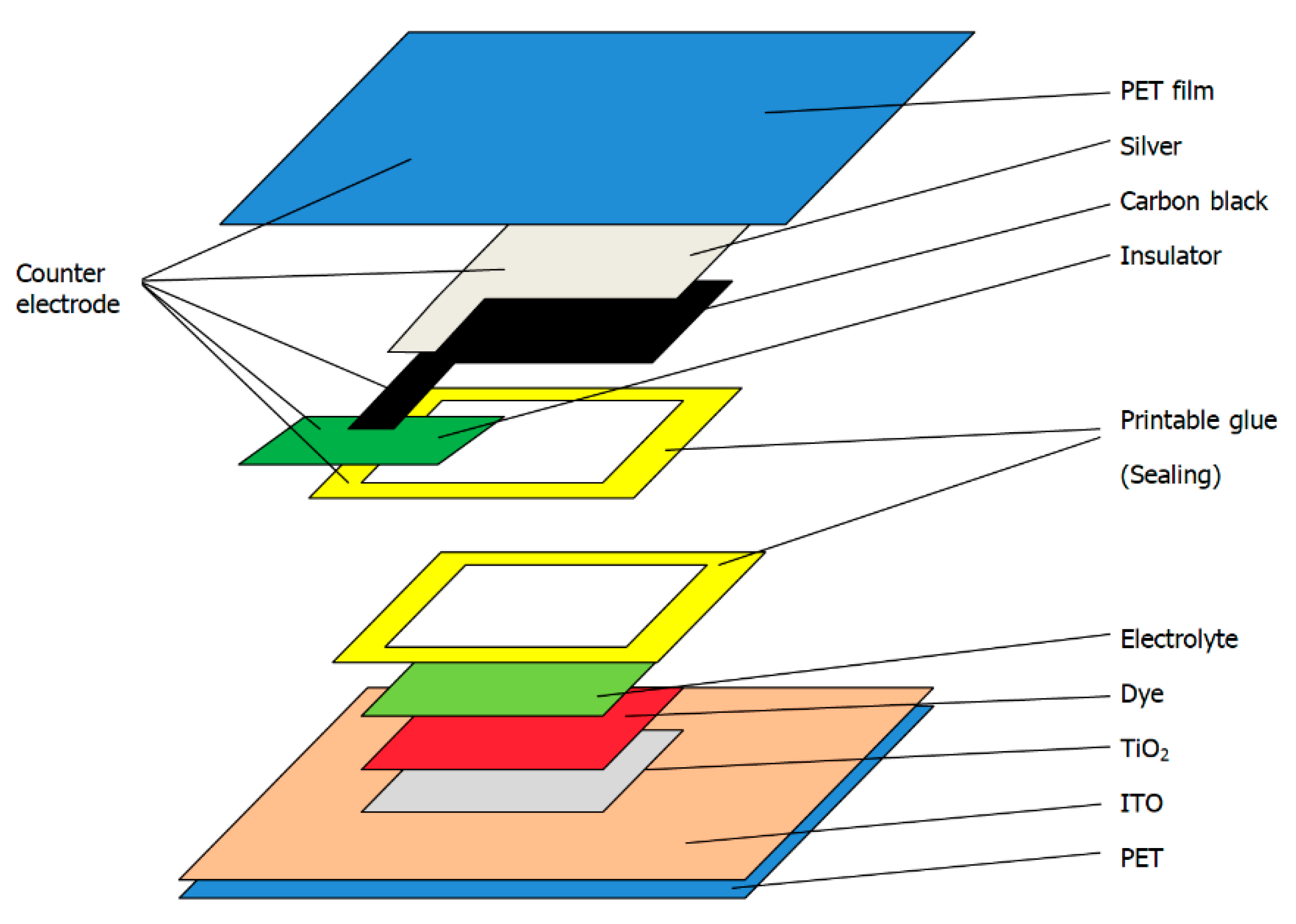
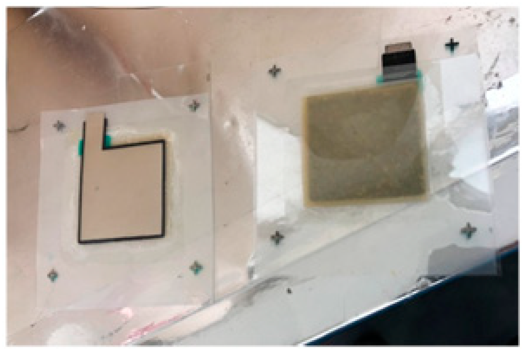
2.2.5. Preparation of the Dye-Sensitized Solar Cells
3. Characterizations
4. Results
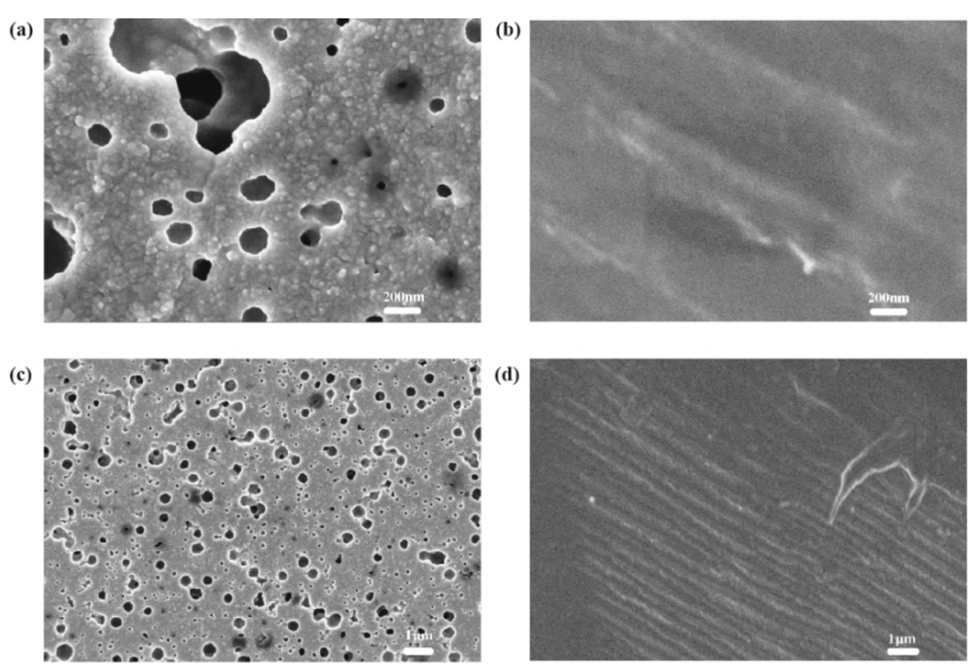
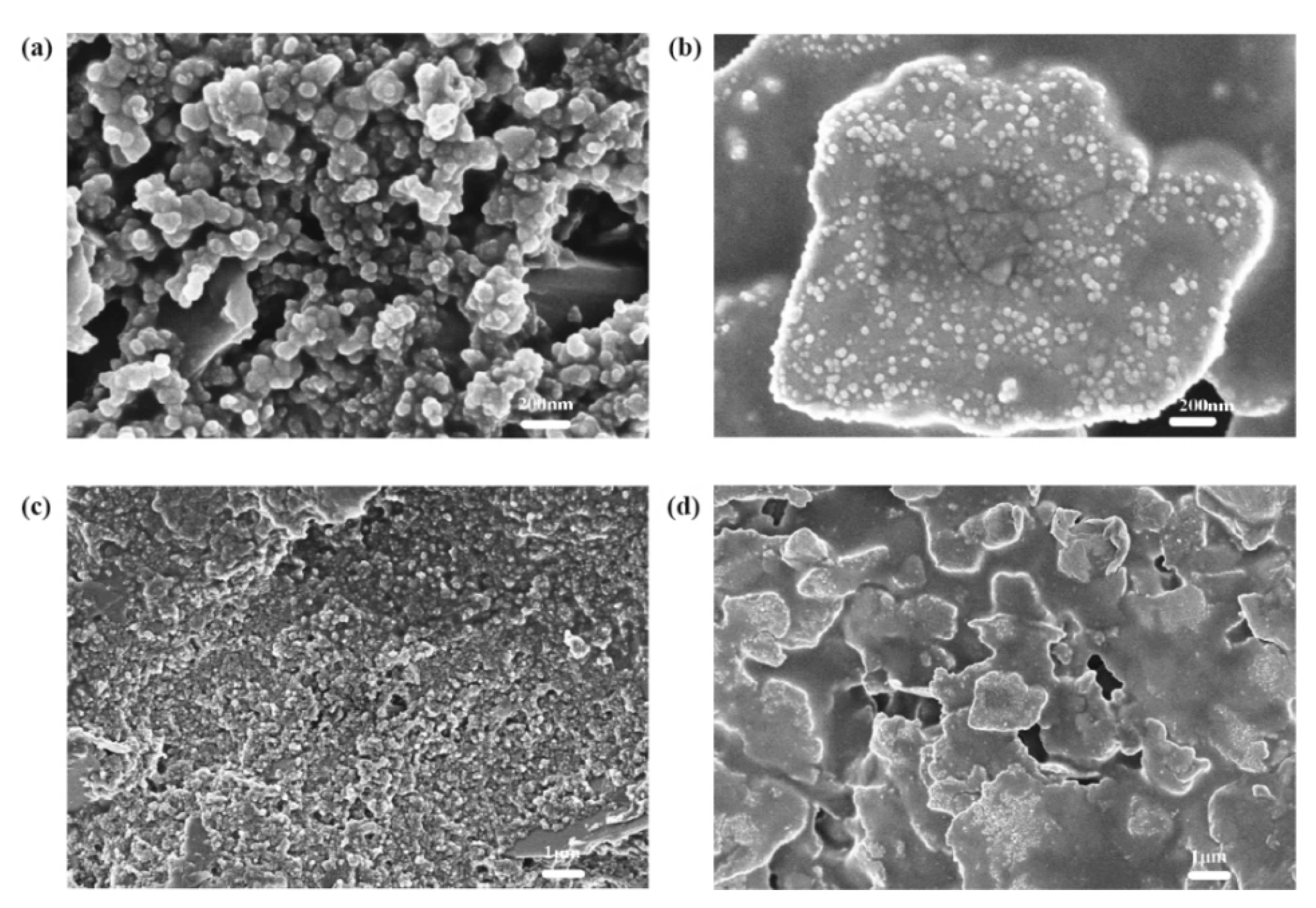
4.1. TiO2 Layer
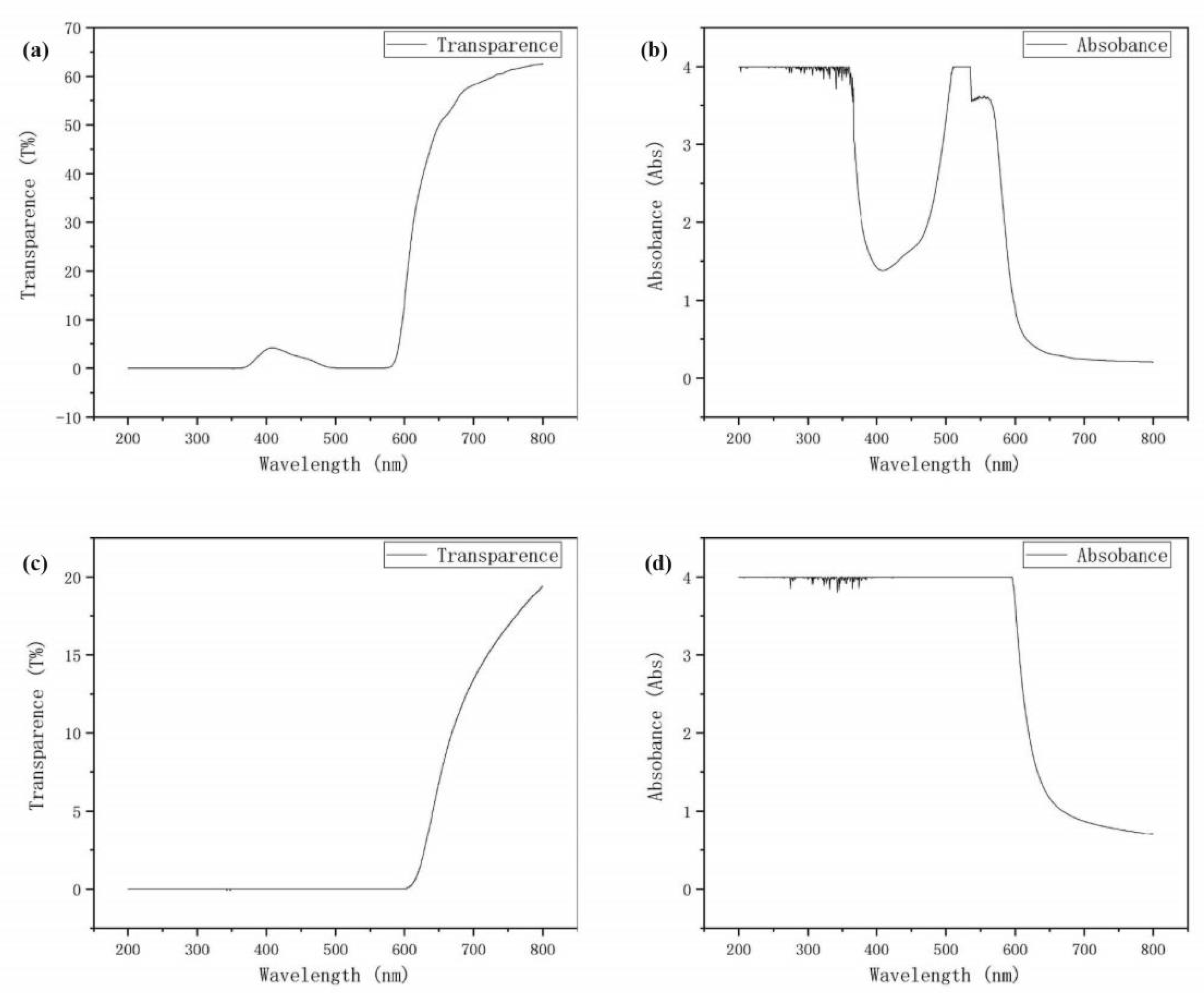
4.2. Dye Layer
4.3. Electrolyte Layer
4.4. Counter Electrode
5. Conclusions
Author Contributions
Funding
Institutional Review Board Statement
Informed Consent Statement
Data Availability Statement
Conflicts of Interest
References
- Yoshikawa, K.; Kawasaki, H.; Yoshida, W.; Irie, T.; Konishi, K.; Nakano, K.; Uto, T.; Adachi, D.; Kanematsu, M.; Uzu, H.; et al. Silicon heterojunction solar cell with interdigitated back contacts for a photoconversion efficiency over 26%. Nat. Energy 2017, 2, 17032. [Google Scholar] [CrossRef]
- Jean, J.; Brown, P.R.; Jaffe, R.L.; Buonassisi, T.; Bulovic, V. Pathways for solar photovoltaics. Energy Environ. Sci. 2015, 8, 1200–1219. [Google Scholar] [CrossRef]
- Schultz, O.; Glunz, S.W.; Willeke, G.P. Multicrystalline silicon solar cells exceeding 20% efficiency. Prog. Photovolt. Res. Appl. 2012, 12, 553–558. [Google Scholar] [CrossRef]
- O’Regan, B.; Graetzel, M. A low-cost, high-efficiency solar cell based on dye-sensitized colloidal TiO2 films. Nat. Mater. 2010, 9, S27–S29. [Google Scholar] [CrossRef]
- Nazeeruddin, M.K.; Pechy, P.; Graetzel, M. Efficient panchromatic sensitization of nanocrystalline TiO2 films by a black dye based on a trithiocyanato-tuthenium complex. Chem. Commun. 1997, 18, 1705–1706. [Google Scholar] [CrossRef]
- Antonio, A.; Planells, M.; Hollman, D.J.; Stranks, S.D.; Petrozza, A.; Kandada, A.R.S.; Vaynzof, Y.; Pathak, S.K.; Robertson, N.; Snaith, H.J. An organic “donor-free” dye with enhanced open-circuit voltage in solid-state sensitized solar cells. Adv. Energy Mater. 2014, 4, 1400166. [Google Scholar]
- Omar, A.; Fakir, M.S.; Hamdan, K.S.; Hamdan, K.S.; Rased, N.H.; Rahim, N.A. Chemical, optical and photovoltaic properties of TiO2/reduced graphene oxide photoanodes sensitized with Roselle and N719 dyes for dye-sensitized solar cell application. Pigment. Resin Technol. 2020, 49, 315–324. [Google Scholar] [CrossRef]
- Murakami, T.N.; Kay, A.; Ito, S.; Wang, Q. Highly efficient dye-sensitized solar cells based on carbon black counter electrodes. J. Electrochem. Soc. 2006, 153, A2255–A2261. [Google Scholar] [CrossRef]
- Wen, Y.; Xu, J. Scientific Importance of water-processable PEDOT:PSS and preparation, challenge and new application in sensors of its film electrode: A Review. J. Polym. Sci. Part. A Polym. Chem. 2017, 55, 1121–1150. [Google Scholar] [CrossRef] [Green Version]
- Lorenz, A.; Senne, A.; Rohde, J.; Kroh, S.; Wittenberg, M.; Krueger, K.; Clement, F.; Biro, D. Evaluation of flexographic printing technology for multi-busbar solar cells. Energy Procedia 2015, 67, 126–137. [Google Scholar] [CrossRef]
- Krebs, F.C. Polymer solar cell modules prepared using roll-to-roll methods: Knife-over-edge coating, slot-die coating and screen printing. Sol. Energy Mater. Sol. Cells 2009, 93, 465–475. [Google Scholar] [CrossRef]
- Tran, T.S.; Dutta, N.K.; Choudhury, N.R. Graphene inks for printed flexible electronics: Graphene dispersions, ink formulations, printing techniques and applications. Adv. Colloid Interface Sci. 2018, 261, 41–61. [Google Scholar] [CrossRef] [PubMed]
- Kim, S.; Moon, H.; Kwon, H.; Lee, G.; Yu, D.; Choi, J.; Park, J.; Kim, S.J.; Yoo, S. Organic Vapor-Jet Printing with Reduced Heat Transfer for Fabrication of Flexible Organic Devices. Adv. Mater. Technol. 2019, 4, 1800332. [Google Scholar] [CrossRef]
- Song, D.; Li, M.; Jiang, Y.; Chen, Z.; Bai, F.; Li, Y.; Jiang, B. Facile fabrication of MoS2/PEDOT: PSS composites as low-cost and efficient counter electrodes for dye-sensitized solar cells. J. Photochem. Photobiol. A Chem. 2014, 279, 47–51. [Google Scholar] [CrossRef]
- Ke, C.R.; Chang, C.C.; Ting, J.M. Modified conducting polymer films having high catalytic activity for use as counter electrodes in rigid and flexible dye-sensitized solar cells. J. Power Sources 2015, 284, 489–496. [Google Scholar] [CrossRef]
- Wu, K.; Ma, J.; Cui, W.; Ruan, B.; Wu, M. The impact of metal ion doping on the performance of flexible poly(3,4-ethylenedioxythiophene) (PEDOT) cathode in dye-sensitized solar cells. J. Photochem. Photobiol. A Chem. 2017, 340, 29–34. [Google Scholar] [CrossRef]
- Ragoussi, M.E.; Torres, T. New generation solar cells: Concepts, trends and perspectives. Chem. Commun. 2015, 51, 3957–3972. [Google Scholar] [CrossRef] [Green Version]
- Sekar, N.; Gehlot, V.Y. Metal complex dyes for dye-sensitized solar cells: Recent development. Resonance 2010, 15, 819–831. [Google Scholar] [CrossRef]
- Horiuchi, T.; Miura, H.; Sumioka, K.; Uchida, S. High efficiency of dye-sensitized solar cells based on metal-free indoline dyes. J. Am. Chem. Soc. 2004, 126, 12218–12219. [Google Scholar] [CrossRef]
- Bella, F.; Vlachopoulos, N.; Nonomura, K.; Zakeeruddin, S.M.; Grätzel, M.; Gerbaldi, C.; Hagfeldt, A. Direct light-induced polymerization of cobalt-based redox shuttles: An ultrafast way towards stable dye-sensitized solar cells. Chem. Commun. 2015, 51, 16308–16311. [Google Scholar] [CrossRef] [Green Version]
- Chen, M.; Shao, L. Review on the recent progress of carbon counter electrodes for dye-sensitized solar cells. Chem. Eng. J. 2016, 304, 629–645. [Google Scholar] [CrossRef]
- Ghifari, A.; Long, D.X.; Kim, S.; Ma, B.; Hong, J. Transparent Platinum Counter Electrode Prepared by Polyol Reduction for Bifacial. Dye-Sensitized Sol. Cells Nanomater. 2020, 10, 217. [Google Scholar]
- Lee, W.J.; Ramasamy, E.; Lee, D.Y.; Song, J.S. Glass frit overcoated silver grid lines for nano-crystalline dye sensitized solar cells. J. Photochem. Photobiol. A Chem. 2006, 183, 133–137. [Google Scholar] [CrossRef]
- Liu, J.; Li, Y.; Arumugam, S.; Tudor, J.; Beeby, S. Investigation of low temperature processed titanium dioxide (TiO2) films for printed dye sensitized solar cells (DSSCs) for large area flexible applications. Mater. Today Proc. 2018, 5, 13846–13854. [Google Scholar] [CrossRef]


| 1 | 2 | 3 | 4 | 5 | 6 | |
|---|---|---|---|---|---|---|
| Voc | 0.65 V | 0.60 V | 0.50 V | 0.40 V | 0.30 V | 0.35 V |
| Jsc | 90 μA/cm2 | 80 μA/cm | 50 μA/cm | 40 μA/cm | 30 μA/cm | 22 μA/cm |
| FF | 0.241 | 0.239 | 0.256 | 0.262 | 0.413 | 0.344 |
| Concentration | Conductivity (S) | ||
|---|---|---|---|
| NaCl (Water) | KI (Water) | KI (Acetonitrile) | |
| 5% | 79 | 51 | / |
| 10% | 138 | 99 | / |
| 15% | 191.5 | 143 | / |
| 20% | 225 | 185 | / |
| 30% | / | 268 | / |
| 40% | / | 314 | / |
| 50% | / | 404 | / |
| Saturated | 251 | 482 | 12.6 |
| 1 | 2 | 3 | 4 | 5 | 6 | |
|---|---|---|---|---|---|---|
| Voc | 0.65 V | 0.60 V | 0.55 V | 0.45 V | 0.35 V | 0.30 V |
| Jsc | 90 μA/cm2 | 60 μA/cm | 40 μA/cm | 30 μA/cm | 20 μA/cm | 10 μA/cm |
| FF | 0.241 | 0.283 | 0.247 | 0.265 | 0.302 | 0.276 |
Publisher’s Note: MDPI stays neutral with regard to jurisdictional claims in published maps and institutional affiliations. |
© 2021 by the authors. Licensee MDPI, Basel, Switzerland. This article is an open access article distributed under the terms and conditions of the Creative Commons Attribution (CC BY) license (https://creativecommons.org/licenses/by/4.0/).
Share and Cite
Cao, C.; Yang, T.; Chen, G. Hibiscus Leachate Dye-Based Low-Cost and Flexible Dye-Sensitized Solar Cell Prepared by Screen Printing. Materials 2021, 14, 2748. https://doi.org/10.3390/ma14112748
Cao C, Yang T, Chen G. Hibiscus Leachate Dye-Based Low-Cost and Flexible Dye-Sensitized Solar Cell Prepared by Screen Printing. Materials. 2021; 14(11):2748. https://doi.org/10.3390/ma14112748
Chicago/Turabian StyleCao, Congjun, Tianning Yang, and Guangxue Chen. 2021. "Hibiscus Leachate Dye-Based Low-Cost and Flexible Dye-Sensitized Solar Cell Prepared by Screen Printing" Materials 14, no. 11: 2748. https://doi.org/10.3390/ma14112748