
Synthesis Route, Microstructural Evolution, and Mechanical Property Relationship of High-Entropy Alloys (HEAs): A Review

 ,
,  , and
, and
Abstract
:1. Introduction
2. Microstructural Evolution of HEAs Synthesized through the Melting and Casting Route
3. Powder Metallurgy
3.1. Mechanical Alloying (MA)
3.2. Spark Plasma Sintering (SPS)
3.3. Microstructural Evolution of HEAs Synthesized Using Powder Metallurgy
4. Microstructural Evolution of HEAs Fabricated by Additive Manufacturing (AM)
5. Mechanical Properties
5.1. Solid Solution Hardening
5.2. Precipitation Hardening
5.3. Grain Boundary Strengthening
5.4. Dislocation Hardening
6. Concluding Remarks
7. Recommendations for Future Studies
Author Contributions
Funding
Institutional Review Board Statement
Informed Consent Statement
Data Availability Statement
Acknowledgments
Conflicts of Interest
References
- Yeh, J.-W.; Chen, S.-K.; Lin, S.-J.; Gan, J.-Y.; Chin, T.-S.; Shun, T.-T.; Tsau, C.-H.; Chang, S.-Y. Nanostructured High-Entropy Alloys with Multiple Principal Elements: Novel Alloy Design Concepts and Outcomes. Adv. Eng. Mater. 2004, 6, 299–303. [Google Scholar] [CrossRef]
- Miracle, D.B.; Senkov, O.N. A critical review of high entropy alloys and related concepts. Acta Mater. 2017, 122, 448–511. [Google Scholar] [CrossRef] [Green Version]
- Li, Z.; Zhao, S.; Ritchie, R.O.; Meyers, M.A. Mechanical properties of high-entropy alloys with emphasis on face-centered cubic alloys. Prog. Mater. Sci. 2019, 102, 296–345. [Google Scholar] [CrossRef]
- Murty, B.S.; Yeh, J.W.; Ranganathan, S.; Bhattacharjee, P.P. 1-A brief history of alloys and the birth of high-entropy alloys. In High-Entropy Alloys, 2nd ed.; Murty, B.S., Yeh, J.W., Ranganathan, S., Bhattacharjee, P.P., Eds.; Elsevier: Amsterdam, The Netherlands, 2019; pp. 1–12. [Google Scholar]
- Poletti, M.G.; McCaughey, C.M.; Fiore, G.; Goodall, R.; Battezzati, L. Refractory high entropy alloys: CrMoNbTiVWZr and AlxCryNbMoTiVzZry(x = 0,0.6;y = 0.3,z = 0,0.6). Int. J. Refract. Met. Hard Mater. 2018, 76, 128–133. [Google Scholar] [CrossRef]
- Wu, D.; Kusada, K.; Yamamoto, T.; Toriyama, T.; Matsumura, S.; Kawaguchi, S.; Kubota, Y.; Kitagawa, H. Platinum-Group-Metal High-Entropy-Alloy Nanoparticles. J. Am. Chem. Soc. 2020, 142, 13833–13838. [Google Scholar] [CrossRef] [PubMed]
- Feng, R.; Gao, M.C.; Zhang, C.; Guo, W.; Poplawsky, J.D.; Zhang, F.; Hawk, J.A.; Neuefeind, J.C.; Ren, Y.; Liaw, P.K. Phase stability and transformation in a light-weight high-entropy alloy. Acta Mater. 2018, 146, 280–293. [Google Scholar] [CrossRef]
- Tseng, K.-K.; Yang, Y.; Juan, C.; Chin, T.; Tsai, C.; Yeh, J.-W. A light-weight high-entropy alloy Al20Be20Fe10Si15Ti35. Sci. China Technol. Sci. 2017, 61. [Google Scholar] [CrossRef]
- Santodonato, L.J.; Zhang, Y.; Feygenson, M.; Parish, C.M.; Gao, M.C.; Weber, R.J.; Neuefeind, J.C.; Tang, Z.; Liaw, P.K. Deviation from high-entropy configurations in the atomic distributions of a multi-principal-element alloy. Nat. Commun. 2015, 6, 5964. [Google Scholar] [CrossRef] [Green Version]
- Vintila, R.; Charest, A.; Drew, R.; Brochu, M. Synthesis and consolidation via spark plasma sintering of nanostructured Al-5356/B4C composite. Mater. Sci. Eng. A 2011, 528, 4395–4407. [Google Scholar] [CrossRef]
- Pickering, E.J.; Muñoz-Moreno, R.; Stone, H.J.; Jones, N.G. Precipitation in the equiatomic high-entropy alloy CrMnFeCoNi. Scr. Mater. 2016, 113, 106–109. [Google Scholar] [CrossRef]
- Zhang, Y.; Zhou, Y.J.; Lin, J.P.; Chen, G.L.; Liaw, P.K. Solid-Solution Phase Formation Rules for Multi-component Alloys. Adv. Eng. Mater. 2008, 10, 534–538. [Google Scholar] [CrossRef]
- Tian, F.; Varga, L.K.; Chen, N.; Shen, J.; Vitos, L. Empirical design of single phase high-entropy alloys with high hardness. Intermetallics 2015, 58, 1–6. [Google Scholar] [CrossRef]
- Kucza, W.; Dąbrowa, J.; Cieślak, G.; Berent, K.; Kulik, T.; Danielewski, M. Studies of “sluggish diffusion” effect in Co-Cr-Fe-Mn-Ni, Co-Cr-Fe-Ni and Co-Fe-Mn-Ni high entropy alloys; determination of tracer diffusivities by combinatorial approach. J. Alloy. Compd. 2018, 731, 920–928. [Google Scholar] [CrossRef]
- Zou, Y.; Maiti, S.; Steurer, W.; Spolenak, R. Size-dependent plasticity in an Nb25Mo25Ta25W25 refractory high-entropy alloy. Acta Mater. 2014, 65, 85–97. [Google Scholar] [CrossRef]
- Zhang, K.; Wang, H. Effects of Annealing Treatment on Phase Composition and Microstructure of CoCrFeNiTiAlx High-Entropy Alloys. Intermetallics 2012, 22, 24–32. [Google Scholar] [CrossRef]
- Kao, Y.-F.; Chen, T.-J.; Lee, P.-H.; Yeh, J.-W. Microstructure and Mechanical Property of As-Cast, Homogenized, and Deformed AlxCoCrFeNi (0 ≤ x ≤ 2) High-Entropy Alloys. J. Alloys Compd. 2009, 488, 57–64. [Google Scholar] [CrossRef]
- Li, C.; Li, J.; Zhao, M.; Jiang, Q. Effect of alloying elements on microstructure and properties of multiprincipal elements high-entropy alloys. J. Alloys Compd. 2009, 475, 752–757. [Google Scholar] [CrossRef]
- George, E.P.; Raabe, D.; Ritchie, R.O. High-entropy alloys. Nat. Rev. Mater. 2019, 4, 515–534. [Google Scholar] [CrossRef]
- Yeh, J.-W. Alloy Design Strategies and Future Trends in High-Entropy Alloys. JOM 2013, 65. [Google Scholar] [CrossRef]
- Ye, Y.; Wang, Q.; Lu, J.; Liu, C.; Yang, Y. High-entropy alloy: Challenges and prospects. Mater. Today 2016, 19, 349–362. [Google Scholar] [CrossRef]
- Kottke, J.; Laurent-Brocq, M.; Fareed, A.; Gaertner, D.; Perrière, L.; Rogal, Ł.; Divinski, S.V.; Wilde, G. Tracer diffusion in the Ni–CoCrFeMn system: Transition from a dilute solid solution to a high entropy alloy. Scr. Mater. 2019, 159, 94–98. [Google Scholar] [CrossRef]
- Sathiyamoorthi, P.; Basu, J.; Kashyap, S.; Pradeep, K.; Kottada, R.S. Thermal stability and grain boundary strengthening in ultrafine-grained CoCrFeNi high entropy alloy composite. Mater. Des. 2017, 134, 426–433. [Google Scholar] [CrossRef]
- Khan, I.; Mostafa, A.; Aljarrah, M.; Essadiqi, E.; Medraj, M. Influence of cooling rate on microsegregation behavior of magnesium alloys. J. Mater. 2014, 2014, 657647. [Google Scholar] [CrossRef]
- Ghiaasiaan, R.; Zeng, X.; Shankar, S. Controlled Diffusion Solidification (CDS) of Al-Zn-Mg-Cu (7050): Microstructure, heat treatment and mechanical properties. Mater. Sci. Eng. A 2014, 594, 260–277. [Google Scholar] [CrossRef]
- Manzoni, A.; Daoud, H.; Völkl, R.; Glatzel, U.; Wanderka, N. Phase separation in equiatomic AlCoCrFeNi high-entropy alloy. Ultramicroscopy 2013, 132, 212–215. [Google Scholar] [CrossRef]
- Wang, F.J.; Zhang, Y. Effect of Co addition on crystal structure and mechanical properties of Ti0.5CrFeNiAlCo high entropy alloy. Mater. Sci. Eng. A 2008, 496, 214–216. [Google Scholar] [CrossRef]
- Tian, Q.; Zhang, G.; Yin, K.; Wang, W.; Cheng, W.; Wang, Y. The strengthening effects of relatively lightweight AlCoCrFeNi high entropy alloy. Mater. Charact. 2019, 151, 302–309. [Google Scholar] [CrossRef]
- Lv, Y.; Hu, R.; Yao, Z.; Chen, J.; Xu, D.; Liu, Y.; Fan, X. Cooling rate effect on microstructure and mechanical properties of AlxCoCrFeNi high entropy alloys. Mater. Des. 2017, 132, 392–399. [Google Scholar] [CrossRef]
- Verma, A.; Kumar, S.; Grant, P.; O’Reilly, K. Influence of cooling rate on the Fe intermetallic formation in an AA6063 Al alloy. J. Alloy. Compd. 2013, 555, 274–282. [Google Scholar] [CrossRef]
- Wang, F.; Zhang, Y.; Chen, G.; Davies, H. Cooling rate and size effect on the microstructure and mechanical properties of AlCoCrFeNi high entropy alloy. J. Eng. Mater. Technol. 2009, 131, 034501. [Google Scholar] [CrossRef]
- Kozieł, T. Estimation of cooling rates in suction casting and copper-mould casting processes. Arch. Metall. Mater. 2015, 60, 767–771. [Google Scholar] [CrossRef]
- Qiu, Y.; Hu, Y.; Taylor, A.; Styles, M.; Marceau, R.; Ceguerra, A.; Gibson, M.; Liu, Z.; Fraser, H.; Birbilis, N. A lightweight single-phase AlTiVCr compositionally complex alloy. Acta Mater. 2017, 123, 115–124. [Google Scholar] [CrossRef] [Green Version]
- Wang, X.; Xie, H.; Jia, L.; Lu, Z.L. Effect of Ti, Al and Cu Addition on Structural Evolution and Phase Constitution of FeCoNi System Equimolar Alloys. Mater. Sci. Forum 2012, 724, 335–338. [Google Scholar] [CrossRef]
- Sobol’, O.; Andreev, A.; Gorban’, V.; Krapivka, N.; Stolbovoi, V.; Serdyuk, I.; Fil’chikov, V. Reproducibility of the single-phase structural state of the multielement high-entropy Ti-V-Zr-Nb-Hf system and related superhard nitrides formed by the vacuum-arc method. Tech. Phys. Lett. 2012, 38, 616–619. [Google Scholar] [CrossRef]
- Dong, Y.; Jiang, L.; Jiang, H.; Lu, Y.; Wang, T.; Li, T. Effects of annealing treatment on microstructure and hardness of bulk AlCrFeNiMo0.2 eutectic high-entropy alloy. Mater. Des. 2015, 82, 91–97. [Google Scholar] [CrossRef]
- Liu, C.M.; Wang, H.M.; Zhang, S.Q.; Tang, H.B.; Zhang, A.L. Microstructure and oxidation behavior of new refractory high entropy alloys. J. Alloy. Compd. 2014, 583, 162–169. [Google Scholar] [CrossRef]
- Zhang, Y.; Zuo, T.; Cheng, Y.; Liaw, P.K. High-entropy Alloys with High Saturation Magnetization, Electrical Resistivity and Malleability. Sci. Rep. 2013, 3, 1455. [Google Scholar] [CrossRef] [Green Version]
- Senkov, O.N.; Wilks, G.B.; Miracle, D.B.; Chuang, C.P.; Liaw, P.K. Refractory high-entropy alloys. Intermetallics 2010, 18, 1758–1765. [Google Scholar] [CrossRef]
- Senkov, O.N.; Wilks, G.; Scott, J.; Miracle, D.B. Mechanical properties of Nb25Mo25Ta25W25 and V20Nb20Mo20Ta20W20 refractory high entropy alloys. Intermetallics 2011, 19, 698–706. [Google Scholar] [CrossRef]
- Tsai, M.-H.; Tsai, K.-Y.; Tsai, C.-W.; Lee, C.; Juan, C.-C.; Yeh, J.-W. Criterion for sigma phase formation in Cr-and V-containing high-entropy alloys. Mater. Res. Lett. 2013, 1, 207–212. [Google Scholar] [CrossRef] [Green Version]
- Shaysultanov, D.G.; Salishchev, G.A.; Ivanisenko, Y.V.; Zherebtsov, S.V.; Tikhonovsky, M.A.; Stepanov, N.D. Novel Fe36Mn21Cr18Ni15Al10 high entropy alloy with bcc/B2 dual-phase structure. J. Alloys Compd. 2017, 705, 756–763. [Google Scholar] [CrossRef]
- Cui, H.B.; Zheng, L.F.; Wang, J.Y. Microstructure Evolution and Corrosion Behavior of Directionally Solidified FeCoNiCrCu High Entropy Alloy. Appl. Mech. Mater. 2011, 66–68, 146–149. [Google Scholar] [CrossRef]
- Ma, Y.; Liu, X.; Dong, W.; Li, R.; Zhang, Y.; Lu, Y.; Yu, P.; Li, G. Interstitial carbide synergistically strengthening high-entropy alloy CoCrFeNiV0.5Cx. Mater. Sci. Eng. A 2020, 792, 139802. [Google Scholar] [CrossRef]
- Deng, Y.; Tasan, C.C.; Pradeep, K.G.; Springer, H.; Kostka, A.; Raabe, D. Design of a twinning-induced plasticity high entropy alloy. Acta Mater. 2015, 94, 124–133. [Google Scholar] [CrossRef]
- Yao, M.J.; Pradeep, K.G.; Tasan, C.C.; Raabe, D. A novel, single phase, non-equiatomic FeMnNiCoCr high-entropy alloy with exceptional phase stability and tensile ductility. Scr. Mater. 2014, 72–73, 5–8. [Google Scholar] [CrossRef]
- Tian, F.; Delczeg, L.; Chen, N.; Varga, L.K.; Shen, J.; Vitos, L. Structural stability of NiCoFeCrAl$ high-entropy alloy from ab initio theory. Phys. Rev. B 2013, 88, 085128. [Google Scholar] [CrossRef]
- Shun, T.-T.; Chang, L.-Y.; Shiu, M.-H. Microstructures and mechanical properties of multiprincipal component CoCrFeNiTix alloys. Mater. Sci. Eng. A 2012, 556, 170–174. [Google Scholar] [CrossRef]
- Li, B.-y.; Peng, K.; Hu, A.-p.; Zhou, L.-p.; Zhu, J.-j.; Li, D.-y. Structure and properties of FeCoNiCrCu0.5Alx high-entropy alloy. Trans. Nonferrous Met. Soc. China 2013, 23, 735–741. [Google Scholar] [CrossRef]
- He, F.; Wang, Z.; Niu, S.; Wu, Q.; Li, J.; Wang, J.; Liu, C.T.; Dang, Y. Strengthening the CoCrFeNiNb0.25 high entropy alloy by FCC precipitate. J. Alloys Compd. 2016, 667, 53–57. [Google Scholar] [CrossRef]
- Chuang, M.-H.; Tsai, M.-H.; Wang, W.-R.; Lin, S.-J.; Yeh, J.-W. Microstructure and wear behavior of AlxCo1.5CrFeNi1.5Tiy high-entropy alloys. Acta Mater. 2011, 59, 6308–6317. [Google Scholar] [CrossRef]
- Chou, Y.L.; Yeh, J.W.; Shih, H.C. The effect of molybdenum on the corrosion behaviour of the high-entropy alloys Co1.5CrFeNi1.5Ti0.5Mox in aqueous environments. Corros. Sci. 2010, 52, 2571–2581. [Google Scholar] [CrossRef]
- Law, J.Y.; Moreno-Ramírez, L.M.; Díaz-García, Á.; Martín-Cid, A.; Kobayashi, S.; Kawaguchi, S.; Nakamura, T.; Franco, V. MnFeNiGeSi high-entropy alloy with large magnetocaloric effect. J. Alloys Compd. 2021, 855, 157424. [Google Scholar] [CrossRef]
- Masemola, K.; Popoola, P.; Malatji, N. The effect of annealing temperature on the microstructure, mechanical and electrochemical properties of arc-melted AlCrFeMnNi equi-atomic High entropy alloy. J. Mater. Res. Technol. 2020, 9, 5241–5251. [Google Scholar] [CrossRef]
- Wu, Q.; Wang, Z.; Zheng, T.; Chen, D.; Yang, Z.; Li, J.; Kai, J.-j.; Wang, J. A casting eutectic high entropy alloy with superior strength-ductility combination. Mater. Lett. 2019, 253, 268–271. [Google Scholar] [CrossRef]
- Chen, S.-T.; Tang, W.-Y.; Kuo, Y.-F.; Chen, S.-Y.; Tsau, C.-H.; Shun, T.-T.; Yeh, J.-W. Microstructure and properties of age-hardenable AlxCrFe1.5MnNi0.5 alloys. Mater. Sci. Eng. A 2010, 527, 5818–5825. [Google Scholar] [CrossRef]
- Kao, Y.-F.; Chen, S.-K.; Chen, T.-J.; Chu, P.-C.; Yeh, J.-W.; Lin, S.-J. Electrical, magnetic, and Hall properties of AlxCoCrFeNi high-entropy alloys. J. Alloy. Compd. 2011, 509, 1607–1614. [Google Scholar] [CrossRef]
- Ren, B.; Liu, Z.; Li, D.; Shi, L.; Cai, B.; Wang, M. Effect of elemental interaction on microstructure of CuCrFeNiMn high entropy alloy system. J. Alloy. Compd. 2010, 493, 148–153. [Google Scholar] [CrossRef]
- Ren, B.; Liu, Z.; Cai, B.; Wang, M.; Shi, L. Aging behavior of a CuCr2Fe2NiMn high-entropy alloy. Mater. Des. 2012, 33, 121–126. [Google Scholar] [CrossRef]
- He, J.Y.; Liu, W.H.; Wang, H.; Wu, Y.; Liu, X.J.; Nieh, T.G.; Lu, Z.P. Effects of Al addition on structural evolution and tensile properties of the FeCoNiCrMn high-entropy alloy system. Acta Mater. 2014, 62, 105–113. [Google Scholar] [CrossRef]
- Pauzi, S.S.M.; Darham, W.; Ramli, R.; Harun, M.; Talari, M.K. Effect of Zr Addition on Microstructure and Properties of FeCrNiMnCoZr x and Al 0.5 FeCrNiMnCoZr x High Entropy Alloys. Trans. Indian Inst. Met. 2013, 66, 305–308. [Google Scholar] [CrossRef]
- Wang, C.W.; Mo, Z.Q.; Tang, J.J. The Study about Microstructure Characterization of AlCoCrTiNiCu_x High Entropy Alloy System with Multi-principal element. Adv. Mater. Res. 2012, 399, 3–7. [Google Scholar] [CrossRef]
- Mishra, A.K.; Samal, S.; Biswas, K. Solidification behaviour of Ti–Cu–Fe–Co–Ni high entropy alloys. Trans. Indian Inst. Met. 2012, 65, 725–730. [Google Scholar] [CrossRef]
- Zhang, K.B.; Fu, Z.Y.; Zhang, J.Y.; Shi, J.; Wang, W.M.; Wang, H.; Wang, Y.C.; Zhang, Q.J. Annealing on the structure and properties evolution of the CoCrFeNiCuAl high-entropy alloy. J. Alloys Compd. 2010, 502, 295–299. [Google Scholar] [CrossRef]
- Wen, L.H.; Kou, H.C.; Li, J.S.; Chang, H.; Xue, X.Y.; Zhou, L. Effect of aging temperature on microstructure and properties of AlCoCrCuFeNi high-entropy alloy. Intermetallics 2009, 17, 266–269. [Google Scholar] [CrossRef]
- Aguilar-Hurtado, J.Y.; Vargas-Uscategui, A.; Zambrano-Mera, D.; Palma-Hillerns, R. The effect of boron content on the microstructure and mechanical properties of Fe50-XMn30Co10Cr10BX (x = 0, 0.3, 0.6 and 1.7 wt%) multi-component alloys prepared by arc-melting. Mater. Sci. Eng. A 2019, 748, 244–252. [Google Scholar] [CrossRef]
- Soare, V.; Mitrica, D.; Constantin, I.; Popescu, G.; Csaki, I.; Tarcolea, M.; Carcea, I. The mechanical and corrosion behaviors of as-cast and re-melted AlCrCuFeMnNi multi-component high-entropy alloy. Metall. Mater. Trans. A 2015, 46, 1468–1473. [Google Scholar] [CrossRef]
- Guo, T.; Li, J.; Wang, J.; Wang, W.Y.; Liu, Y.; Luo, X.; Kou, H.; Beaugnon, E. Microstructure and properties of bulk Al0.5CoCrFeNi high-entropy alloy by cold rolling and subsequent annealing. Mater. Sci. Eng. A 2018, 729, 141–148. [Google Scholar] [CrossRef]
- Lin, C.-M.; Tsai, H.-L. Evolution of microstructure, hardness, and corrosion properties of high-entropy Al0.5CoCrFeNi alloy. Intermetallics 2011, 19, 288–294. [Google Scholar] [CrossRef]
- McAlpine, S.W.; Logan, J.V.; Short, M.P. Predicting single phase stability and segregation in the NbMoTaTi–(W,V) high entropy alloy system with the vacancy exchange potential. Scr. Mater. 2021, 191, 29–33. [Google Scholar] [CrossRef]
- Yi, J.; Tang, S.; Xu, M.; Yang, L.; Wang, L.; Zeng, L. A novel Al0.5CrCuNiV 3d transition metal high-entropy alloy: Phase analysis, microstructure and compressive properties. J. Alloys Compd. 2020, 846, 156466. [Google Scholar] [CrossRef]
- Gao, X.; Lu, Y.; Zhang, B.; Liang, N.; Wu, G.; Sha, G.; Liu, J.; Zhao, Y. Microstructural origins of high strength and high ductility in an AlCoCrFeNi2.1 eutectic high-entropy alloy. Acta Mater. 2017, 141, 59–66. [Google Scholar] [CrossRef]
- Jinhong, P.; Ye, P.; Hui, Z.; Lu, Z. Microstructure and properties of AlCrFeCuNix (0.6≤ x≤ 1.4) high-entropy alloys. Mater. Sci. Eng. A 2012, 534, 228–233. [Google Scholar] [CrossRef]
- Anmin, L.; Zhang, X. Thermodynamic analysis of the simple microstructure of AlCrFeNiCu high-entropy alloy with multi-principal elements. Acta Metall. Sin. 2009, 22, 219–224. [Google Scholar]
- Qi, J.; Cheung, A.M.; Poon, S.J. High Entropy Alloys Mined From Binary Phase Diagrams. Sci. Rep. 2019, 9, 15501. [Google Scholar] [CrossRef] [Green Version]
- Tsao, T.-K.; Yeh, A.-C. The Thermal Stability and Strength of Highly Alloyed Ni3Al. Mater. Trans. 2015, 56, 1905–1910. [Google Scholar] [CrossRef] [Green Version]
- Matusiak, K.; Berent, K.; Marciszko, M.; Cieslak, J. The experimental and theoretical study on influence of Al and Cu contents on phase abundance changes in AlxCuyFeCrNiCo HEA system. J. Alloys Compd. 2019, 790, 837–846. [Google Scholar] [CrossRef]
- Aizenshtein, M.; Strumza, E.; Brosh, E.; Hayun, S. Precipitation kinetics, microstructure, and equilibrium state of A2 and B2 phases in multicomponent Al2.75CoCrFeNi alloy. J. Mater. Sci. 2020, 55, 7016–7028. [Google Scholar] [CrossRef]
- Leong, Z.; Wróbel, J.S.; Dudarev, S.L.; Goodall, R.; Todd, I.; Nguyen-Manh, D. The Effect of Electronic Structure on the Phases Present in High Entropy Alloys. Sci. Rep. 2017, 7, 39803. [Google Scholar] [CrossRef] [PubMed]
- Wang, J.; Shang, S.-L.; Wang, Y.; Mei, Z.-G.; Liang, Y.-F.; Du, Y.; Liu, Z.-K. First-principles calculations of binary Al compounds: Enthalpies of formation and elastic properties. Calphad 2011, 35, 562–573. [Google Scholar] [CrossRef]
- Vaidya, M.; Prasad, A.; Parakh, A.; Murty, B. Influence of sequence of elemental addition on phase evolution in nanocrystalline AlCoCrFeNi: Novel approach to alloy synthesis using mechanical alloying. Mater. Des. 2017, 126, 37–46. [Google Scholar] [CrossRef]
- Das, S.K.; Horbach, J.; Voigtmann, T. Structural relaxation in a binary metallic melt: Molecular dynamics computer simulation of undercooled Al 80 Ni 20. Phys. Rev. B 2008, 78, 064208. [Google Scholar] [CrossRef]
- Dong, Y.; Jiang, L.; Tang, Z.; Lu, Y.; Li, T. Effect of electromagnetic field on microstructure and properties of bulk AlCrFeNiMo 0.2 high-entropy alloy. J. Mater. Eng. Perform. 2015, 24, 4475–4481. [Google Scholar] [CrossRef]
- Zheng, H.; Chen, R.; Qin, G.; Li, X.; Su, Y.; Ding, H.; Guo, J.; Fu, H. Phase separation of AlCoCrFeNi2. 1 eutectic high-entropy alloy during directional solidification and their effect on tensile properties. Intermetallics 2019, 113, 106569. [Google Scholar] [CrossRef]
- Shun, T.-T.; Hung, W.-J. Effects of Cr Content on Microstructure and Mechanical Properties of AlCoCr x FeNi High-Entropy Alloy. Adv. Mater. Sci. Eng. 2018, 2018, 5826467. [Google Scholar] [CrossRef] [Green Version]
- Chaudhary, V.; Gwalani, B.; Soni, V.; Ramanujan, R.V.; Banerjee, R. Influence of Cr Substitution and Temperature on Hierarchical Phase Decomposition in the AlCoFeNi High Entropy Alloy. Sci. Rep. 2018, 8, 15578. [Google Scholar] [CrossRef] [PubMed]
- Tang, Z.; Gao, M.C.; Diao, H.; Yang, T.; Liu, J.; Zuo, T.; Zhang, Y.; Lu, Z.; Cheng, Y.; Zhang, Y.; et al. Aluminum Alloying Effects on Lattice Types, Microstructures, and Mechanical Behavior of High-Entropy Alloys Systems. JOM 2013, 65, 1848–1858. [Google Scholar] [CrossRef]
- Mohanty, A.; Sampreeth, J.K.; Bembalge, O.; Hascoet, J.Y.; Marya, S.; Immanuel, R.J.; Panigrahi, S.K. High temperature oxidation study of direct laser deposited AlXCoCrFeNi (X=0.3,0.7) high entropy alloys. Surf. Coat. Technol. 2019, 380, 125028. [Google Scholar] [CrossRef]
- Butler, T.M.; Weaver, M.L. Oxidation behavior of arc melted AlCoCrFeNi multi-component high-entropy alloys. J. Alloy. Compd. 2016, 674, 229–244. [Google Scholar] [CrossRef]
- Ferrari, V.; Wolf, W.; Zepon, G.; Coury, F.; Kaufman, M.; Bolfarini, C.; Kiminami, C.; Botta, W. Effect of boron addition on the solidification sequence and microstructure of AlCoCrFeNi alloys. J. Alloys Compd. 2019, 775, 1235–1243. [Google Scholar] [CrossRef]
- Guo, L.; Xiao, D.; Wu, W.; Ni, S.; Song, M. Effect of Fe on microstructure, phase evolution and mechanical properties of (AlCoCrFeNi) 100-xFex high entropy alloys processed by spark plasma sintering. Intermetallics 2018, 103, 1–11. [Google Scholar] [CrossRef]
- Wang, W.-R.; Wang, W.-L.; Yeh, J.-W. Phases, microstructure and mechanical properties of AlxCoCrFeNi high-entropy alloys at elevated temperatures. J. Alloys Compd. 2014, 589, 143–152. [Google Scholar] [CrossRef]
- Rogström, L.; Ullbrand, J.; Almer, J.; Hultman, L.; Jansson, B.; Odén, M. Strain evolution during spinodal decomposition of TiAlN thin films. Thin Solid Film. 2012, 520, 5542–5549. [Google Scholar] [CrossRef] [Green Version]
- Tsai, K.Y.; Tsai, M.H.; Yeh, J.W. Sluggish diffusion in Co–Cr–Fe–Mn–Ni high-entropy alloys. Acta Mater. 2013, 61, 4887–4897. [Google Scholar] [CrossRef]
- Anand, G.; Goodall, R.; Freeman, C.L. Role of configurational entropy in body-centred cubic or face-centred cubic phase formation in high entropy alloys. Scr. Mater. 2016, 124, 90–94. [Google Scholar] [CrossRef]
- Mo, Y.; Tian, Z.; Liu, R.; Hou, Z.; Wang, C. Structural evolution during crystallization of rapidly super-cooled copper melt. J. Non-Cryst. Solids 2015, 421, 14–19. [Google Scholar] [CrossRef]
- Zhang, L.; Fan, J.; Liu, D.; Zhang, M.; Yu, P.; Jing, Q.; Ma, M.; Liaw, P.; Li, G.; Liu, R. The microstructural evolution and hardness of the equiatomic CoCrCuFeNi high-entropy alloy in the semi-solid state. J. Alloys Compd. 2018, 745, 75–83. [Google Scholar] [CrossRef]
- Qin, G.; Wang, S.; Chen, R.; Gong, X.; Wang, L.; Su, Y.; Guo, J.; Fu, H. Microstructures and mechanical properties of Nb-alloyed CoCrCuFeNi high-entropy alloys. J. Mater. Sci. Technol. 2018, 34, 365–369. [Google Scholar] [CrossRef]
- Hsu, C.-Y.; Yeh, J.-W.; Chen, S.-K.; Shun, T.-T. Wear resistance and high-temperature compression strength of Fcc CuCoNiCrAl 0.5 Fe alloy with boron addition. MMTA 2004, 35, 1465–1469. [Google Scholar] [CrossRef]
- Gwalani, B.; Choudhuri, D.; Soni, V.; Ren, Y.; Styles, M.; Hwang, J.; Nam, S.; Ryu, H.; Hong, S.H.; Banerjee, R. Cu assisted stabilization and nucleation of L12 precipitates in Al0. 3CuFeCrNi2 fcc-based high entropy alloy. Acta Mater. 2017, 129, 170–182. [Google Scholar] [CrossRef] [Green Version]
- Gwalani, B.; Gorsse, S.; Soni, V.; Carl, M.; Ley, N.; Smith, J.; Ayyagari, A.V.; Zheng, Y.; Young, M.; Mishra, R.S. Role of copper on L12 precipitation strengthened fcc based high entropy alloy. Materialia 2019, 6, 100282. [Google Scholar] [CrossRef]
- Zhou, W.; Fu, L.; Liu, P.; Xu, X.; Chen, B.; Zhu, G.; Wang, X.; Shan, A.; Chen, M. Deformation stimulated precipitation of a single-phase CoCrFeMnNi high entropy alloy. Intermetallics 2017, 85, 90–97. [Google Scholar] [CrossRef]
- Mucsi, G. A review on mechanical activation and mechanical alloying in stirred media mill. Chem. Eng. Res. Des. 2019, 148, 460–474. [Google Scholar] [CrossRef]
- Hebda, M.; Gądek, S.; Skałoń, M.; Kazior, J. Effect of mechanical alloying and annealing on the sintering behaviour of AstaloyCrL powders with SiC and carbon addition. J. Therm. Anal. Calorim. 2013, 113, 395–403. [Google Scholar] [CrossRef] [Green Version]
- Paraskevas, D.; Vanmeensel, K.; Vleugels, J.; Dewulf, W.; Deng, Y.; Duflou, J.R. Spark plasma sintering as a solid-state recycling technique: The case of aluminum alloy scrap consolidation. Materials 2014, 7, 5664–5687. [Google Scholar] [CrossRef] [Green Version]
- Shongwe, M.B.; Ramakokovhu, M.M.; Lethabane, M.L.; Olubambi, P.A. Comparison of spark plasma sintering and hybrid spark plasma sintering of Ni-Fe alloys. In Proceedings of the World Congress on Engineering, San Francisco, CA, USA, 25–27 October 2017. [Google Scholar]
- Chakraborty, S.; Das, P.K.; Ghosh, D. SPARK PLASMA SINTERING AND STRUCTURAL PROPERTIES OF ZrB2 BASED CERAMICS: A REVIEW. Rev. Adv. Mater. Sci. 2016, 44, 182–193. [Google Scholar]
- Saheb, N.; Iqbal, Z.; Khalil, A.; Hakeem, A.S.; Al Aqeeli, N.; Laoui, T.; Al-Qutub, A.; Kirchner, R. Spark plasma sintering of metals and metal matrix nanocomposites: A review. J. Nanomater. 2012, 2012, 18. [Google Scholar] [CrossRef] [Green Version]
- Zhang, X.K.; Huang, J.C.; Lin, P.H.; Liu, T.Y.; Wu, Y.C.; Li, W.P.; Wang, Y.N.; Liao, Y.C.; Jang, J.S.C. Microstructure and mechanical properties of Tix(AlCrVNb)100-x light weight multi-principal element alloys. J. Alloys Compd. 2020, 831, 154742. [Google Scholar] [CrossRef]
- Matizamhuka, W. Spark plasma sintering (SPS)-an advanced sintering technique for structural nanocomposite materials. J. S. Afr. Inst. Min. Metall. 2016, 116, 1171–1180. [Google Scholar] [CrossRef]
- Enayati, M.; Mohamed, F. Application of mechanical alloying/milling for synthesis of nanocrystalline and amorphous materials. Int. Mater. Rev. 2014, 59, 394–416. [Google Scholar] [CrossRef]
- Ji, W.; Fu, Z.; Wang, W.; Wang, H.; Zhang, J.; Wang, Y.; Zhang, F. Mechanical alloying synthesis and spark plasma sintering consolidation of CoCrFeNiAl high-entropy alloy. J. Alloy. Compd. 2014, 589, 61–66. [Google Scholar] [CrossRef]
- Koch, C.C. Nanocrystalline high-entropy alloys. J. Mater. Res. 2017, 32, 3435–3444. [Google Scholar] [CrossRef] [Green Version]
- Chen, W.; Fu, Z.; Fang, S.; Xiao, H.; Zhu, D. Alloying behavior, microstructure and mechanical properties in a FeNiCrCo0.3Al0.7 high entropy alloy. Mater. Des. 2013, 51, 854–860. [Google Scholar] [CrossRef]
- Kumar, A.; Swarnakar, A.K.; Chopkar, M. Phase Evolution and Mechanical Properties of AlCoCrFeNiSix High-Entropy Alloys Synthesized by Mechanical Alloying and Spark Plasma Sintering. J. Mater. Eng. Perform. 2018, 27, 3304–3314. [Google Scholar] [CrossRef]
- Shaofeng, Y.; Zhang, Y.; Xing, Y.; Hang, Z. Enhancement of Mechanical Properties and Corrosion Resistance of Ultra-Fine Grain Al0. 4FeCrCo1. 5NiTi0. 3 High-Entropy Alloy by MA and SPS Technologies. Mater. Sci. 2019, 25, 259–264. [Google Scholar]
- Fang, S.; Chen, W.; Fu, Z. Microstructure and mechanical properties of twinned Al0.5CrFeNiCo0.3C0.2 high entropy alloy processed by mechanical alloying and spark plasma sintering. Mater. Des. (1980–2015) 2014, 54, 973–979. [Google Scholar] [CrossRef]
- Wang, C.; Ji, W.; Fu, Z. Mechanical alloying and spark plasma sintering of CoCrFeNiMnAl high-entropy alloy. Adv. Powder Technol. 2014, 25, 1334–1338. [Google Scholar] [CrossRef]
- Moravcik, I.; Cizek, J.; Zapletal, J.; Kovacova, Z.; Vesely, J.; Minarik, P.; Kitzmantel, M.; Neubauer, E.; Dlouhy, I. Microstructure and mechanical properties of Ni1,5Co1,5CrFeTi0,5 high entropy alloy fabricated by mechanical alloying and spark plasma sintering. Mater. Des. 2017, 119, 141–150. [Google Scholar] [CrossRef]
- Yurkova, A.I.; Cherniavsky, V.V.; Bolbut, V.; Krüger, M.; Bogomol, I. Structure formation and mechanical properties of the high-entropy AlCuNiFeCr alloy prepared by mechanical alloying and spark plasma sintering. J. Alloys Compd. 2019, 786, 139–148. [Google Scholar] [CrossRef]
- Pan, J.; Dai, T.; Lu, T.; Ni, X.; Dai, J.; Li, M. Microstructure and mechanical properties of Nb25Mo25Ta25W25 and Ti8Nb23Mo23Ta23W23 high entropy alloys prepared by mechanical alloying and spark plasma sintering. Mater. Sci. Eng. A 2018, 738, 362–366. [Google Scholar] [CrossRef]
- Fu, Z.; Chen, W.; Wen, H.; Morgan, S.; Chen, F.; Zheng, B.; Zhou, Y.; Zhang, L.; Lavernia, E.J. Microstructure and mechanical behavior of a novel Co20Ni20Fe20Al20Ti20 alloy fabricated by mechanical alloying and spark plasma sintering. Mater. Sci. Eng. A 2015, 644, 10–16. [Google Scholar] [CrossRef]
- Pohan, R.M.; Gwalani, B.; Lee, J.; Alam, T.; Hwang, J.Y.; Ryu, H.J.; Banerjee, R.; Hong, S.H. Microstructures and mechanical properties of mechanically alloyed and spark plasma sintered Al0.3CoCrFeMnNi high entropy alloy. Mater. Chem. Phys. 2018, 210, 62–70. [Google Scholar] [CrossRef]
- Yadav, S.; Sarkar, S.; Aggarwal, A.; Kumar, A.; Biswas, K. Wear and mechanical properties of novel (CuCrFeTiZn)100−xPbx high entropy alloy composite via mechanical alloying and spark plasma sintering. Wear 2018, 410–411, 93–109. [Google Scholar] [CrossRef]
- Syed Ghazi, S.; Ravi, K.R. Phase-evolution in high entropy alloys: Role of synthesis route. Intermetallics 2016, 73, 40–42. [Google Scholar] [CrossRef]
- Wróbel, J.S.; Nguyen-Manh, D.; Lavrentiev, M.Y.; Muzyk, M.; Dudarev, S.L. Phase stability of ternary fcc and bcc Fe-Cr-Ni alloys. Phys. Rev. B 2015, 91, 024108. [Google Scholar] [CrossRef] [Green Version]
- Yang, G.; Park, S.-J. Deformation of single crystals, polycrystalline materials, and thin films: A Review. Materials 2019, 12, 2003. [Google Scholar] [CrossRef] [PubMed] [Green Version]
- Praveen, S.; Murty, B.; Kottada, R.S. Phase evolution and densification behavior of nanocrystalline multicomponent high entropy alloys during spark plasma sintering. JOM 2013, 65, 1797–1804. [Google Scholar] [CrossRef]
- Ma, Y.; Wang, Q.; Jiang, B.; Li, C.; Hao, J.; Li, X.; Dong, C.; Nieh, T. Controlled formation of coherent cuboidal nanoprecipitates in body-centered cubic high-entropy alloys based on Al2 (Ni, Co, Fe, Cr) 14 compositions. Acta Mater. 2018, 147, 213–225. [Google Scholar] [CrossRef]
- Li, C.; Ma, Y.; Hao, J.; Wang, Q.; Pang, S.; Dong, C.; Liaw, P.K. Effect of Ti substitution for Al on the cuboidal nanoprecipitates in Al 0.7 NiCoFeCr 2 high-entropy alloys. J. Mater. Res. 2018, 33, 3266–3275. [Google Scholar] [CrossRef] [Green Version]
- Yurkova, A.; Chernyavsky, V.; Hushchyk, D.; Bilyk, I.; Sergey, N. Nanocrystalline AlNiCoFeCrTi High-Entropy Alloy Resulted from Mechanical Alloying and Annealing. In Proceedings of the 2019 IEEE 9th International Conference Nanomaterials: Applications & Properties (NAP), Odesa, Ukraine, 15–20 September 2019; pp. 1–4. [Google Scholar]
- Zhang, D.; Qiu, D.; Gibson, M.A.; Zheng, Y.; Fraser, H.L.; StJohn, D.H.; Easton, M.A. Additive manufacturing of ultrafine-grained high-strength titanium alloys. Nature 2019, 576, 91–95. [Google Scholar] [CrossRef]
- Chen, Q.; Guillemot, G.; Gandin, C.-A.; Bellet, M. Three-dimensional finite element thermomechanical modeling of additive manufacturing by selective laser melting for ceramic materials. Addit. Manuf. 2017, 16, 124–137. [Google Scholar] [CrossRef] [Green Version]
- Kuwabara, K.; Shiratori, H.; Fujieda, T.; Yamanaka, K.; Koizumi, Y.; Chiba, A. Mechanical and corrosion properties of AlCoCrFeNi high-entropy alloy fabricated with selective electron beam melting. Addit. Manuf. 2018, 23, 264–271. [Google Scholar] [CrossRef]
- Fujieda, T.; Shiratori, H.; Kuwabara, K.; Kato, T.; Yamanaka, K.; Koizumi, Y.; Chiba, A. First demonstration of promising selective electron beam melting method for utilizing high-entropy alloys as engineering materials. Mater. Lett. 2015, 159, 12–15. [Google Scholar] [CrossRef]
- Jung, H.Y.; Peter, N.J.; Gärtner, E.; Dehm, G.; Uhlenwinkel, V.; Jägle, E.A. Bulk nanostructured AlCoCrFeMnNi chemically complex alloy synthesized by laser-powder bed fusion. Addit. Manuf. 2020, 35, 101337. [Google Scholar] [CrossRef]
- Gao, X.; Lu, Y. Laser 3D printing of CoCrFeMnNi high-entropy alloy. Mater. Lett. 2019, 236, 77–80. [Google Scholar] [CrossRef]
- Joo, S.-H.; Kato, H.; Jang, M.; Moon, J.; Tsai, C.; Yeh, J.; Kim, H. Tensile deformation behavior and deformation twinning of an equimolar CoCrFeMnNi high-entropy alloy. Mater. Sci. Eng. A 2017, 689, 122–133. [Google Scholar] [CrossRef]
- Peyrouzet, F.; Hachet, D.; Soulas, R.; Navone, C.; Godet, S.; Gorsse, S. Selective Laser Melting of Al0.3CoCrFeNi High-Entropy Alloy: Printability, Microstructure, and Mechanical Properties. JOM 2019, 71, 3443–3451. [Google Scholar] [CrossRef] [Green Version]
- Guan, S.; Solberg, K.; Wan, D.; Berto, F.; Welo, T.; Yue, T.M.; Chan, K.C. Formation of fully equiaxed grain microstructure in additively manufactured AlCoCrFeNiTi0.5 high entropy alloy. Mater. Des. 2019, 184, 108202. [Google Scholar] [CrossRef]
- Zhou, Y.; Zhang, Y.; Wang, Y.; Chen, G. Solid solution alloys of Al Co Cr Fe Ni Ti x with excellent room-temperature mechanical properties. Appl. Phys. Lett. 2007, 90, 181904. [Google Scholar] [CrossRef]
- Ishimoto, T.; Hagihara, K.; Hisamoto, K.; Sun, S.-H.; Nakano, T. Crystallographic texture control of beta-type Ti–15Mo–5Zr–3Al alloy by selective laser melting for the development of novel implants with a biocompatible low Young’s modulus. Scr. Mater. 2017, 132, 34–38. [Google Scholar] [CrossRef]
- Dinda, G.; Dasgupta, A.; Mazumder, J. Texture control during laser deposition of nickel-based superalloy. Scr. Mater. 2012, 67, 503–506. [Google Scholar] [CrossRef]
- Chauvet, E.; Kontis, P.; Jägle, E.A.; Gault, B.; Raabe, D.; Tassin, C.; Blandin, J.-J.; Dendievel, R.; Vayre, B.; Abed, S. Hot cracking mechanism affecting a non-weldable Ni-based superalloy produced by selective electron Beam Melting. Acta Mater. 2018, 142, 82–94. [Google Scholar] [CrossRef]
- Luo, S.; Gao, P.; Yu, H.; Yang, J.; Wang, Z.; Zeng, X. Selective laser melting of an equiatomic AlCrCuFeNi high-entropy alloy: Processability, non-equilibrium microstructure and mechanical behavior. J. Alloys Compd. 2019, 771, 387–397. [Google Scholar] [CrossRef]
- Li, R.; Niu, P.; Yuan, T.; Cao, P.; Chen, C.; Zhou, K. Selective laser melting of an equiatomic CoCrFeMnNi high-entropy alloy: Processability, non-equilibrium microstructure and mechanical property. J. Alloys Compd. 2018, 746, 125–134. [Google Scholar] [CrossRef]
- Tong, Z.; Liu, H.; Jiao, J.; Zhou, W.; Yang, Y.; Ren, X. Improving the strength and ductility of laser directed energy deposited CrMnFeCoNi high-entropy alloy by laser shock peening. Addit. Manuf. 2020, 35, 101417. [Google Scholar] [CrossRef]
- Yao, H.; Tan, Z.; He, D.; Zhou, Z.; Zhou, Z.; Xue, Y.; Cui, L.; Chen, L.; Wang, G.; Yang, Y. High strength and ductility AlCrFeNiV high entropy alloy with hierarchically heterogeneous microstructure prepared by selective laser melting. J. Alloys Compd. 2020, 813, 152196. [Google Scholar] [CrossRef]
- Vogiatzief, D.; Evirgen, A.; Gein, S.; Molina, V.R.; Weisheit, A.; Pedersen, M. Laser Powder Bed Fusion and Heat Treatment of an AlCrFe2Ni2 High Entropy Alloy. Front. Mater. 2020, 7. [Google Scholar] [CrossRef]
- Lin, D.; Xu, L.; Jing, H.; Han, Y.; Zhao, L.; Minami, F. Effects of annealing on the structure and mechanical properties of FeCoCrNi high-entropy alloy fabricated via selective laser melting. Addit. Manuf. 2020, 32, 101058. [Google Scholar] [CrossRef]
- Wang, R.; Zhang, K.; Davies, C.; Wu, X. Evolution of microstructure, mechanical and corrosion properties of AlCoCrFeNi high-entropy alloy prepared by direct laser fabrication. J. Alloys Compd. 2017, 694, 971–981. [Google Scholar] [CrossRef]
- Moorehead, M.; Bertsch, K.; Niezgoda, M.; Parkin, C.; Elbakhshwan, M.; Sridharan, K.; Zhang, C.; Thoma, D.; Couet, A. High-throughput synthesis of Mo-Nb-Ta-W high-entropy alloys via additive manufacturing. Mater. Des. 2020, 187, 108358. [Google Scholar] [CrossRef]
- Popov, V.V.; Katz-Demyanetz, A.; Koptyug, A.; Bamberger, M. Selective electron beam melting of Al0.5CrMoNbTa0.5 high entropy alloys using elemental powder blend. Heliyon 2019, 5, e01188. [Google Scholar] [CrossRef] [Green Version]
- Welk, B.A.; Williams, R.E.A.; Viswanathan, G.B.; Gibson, M.A.; Liaw, P.K.; Fraser, H.L. Nature of the interfaces between the constituent phases in the high entropy alloy CoCrCuFeNiAl. Ultramicroscopy 2013, 134, 193–199. [Google Scholar] [CrossRef]
- Yue, T.; Xie, H.; Lin, X.; Yang, H.; Meng, G. Solidification behaviour in laser cladding of AlCoCrCuFeNi high-entropy alloy on magnesium substrates. J. Alloys Compd. 2014, 587, 588–593. [Google Scholar] [CrossRef]
- Vikram, R.J.; Murty, B.S.; Fabijanic, D.; Suwas, S. Insights into micro-mechanical response and texture of the additively manufactured eutectic high entropy alloy AlCoCrFeNi2.1. J. Alloys Compd. 2020, 827, 154034. [Google Scholar] [CrossRef]
- Thapliyal, S.; Nene, S.S.; Agrawal, P.; Wang, T.; Morphew, C.; Mishra, R.S.; McWilliams, B.A.; Cho, K.C. Damage-tolerant, corrosion-resistant high entropy alloy with high strength and ductility by laser powder bed fusion additive manufacturing. Addit. Manuf. 2020, 36, 101455. [Google Scholar] [CrossRef]
- Kenel, C.; Casati, N.P.M.; Dunand, D.C. 3D ink-extrusion additive manufacturing of CoCrFeNi high-entropy alloy micro-lattices. Nat. Commun. 2019, 10, 904. [Google Scholar] [CrossRef] [PubMed] [Green Version]
- Kunce, I.; Polanski, M.; Bystrzycki, J. Structure and hydrogen storage properties of a high entropy ZrTiVCrFeNi alloy synthesized using Laser Engineered Net Shaping (LENS). Int. J. Hydrogen Energy 2013, 38, 12180–12189. [Google Scholar] [CrossRef]
- Zhang, H.; Pan, Y.; He, Y.; Jiao, H. Microstructure and properties of 6FeNiCoSiCrAlTi high-entropy alloy coating prepared by laser cladding. Appl. Surf. Sci. 2011, 257, 2259–2263. [Google Scholar] [CrossRef]
- Zheng, B.; Liu, Q.B.; Zhang, L.Y. Microstructure and Properties of MoFeCrTiW High-Entropy Alloy Coating Prepared by Laser Cladding. Adv. Mater. Res. 2013, 820, 63–66. [Google Scholar] [CrossRef]
- Kunce, I.; Polanski, M.; Bystrzycki, J. Microstructure and hydrogen storage properties of a TiZrNbMoV high entropy alloy synthesized using Laser Engineered Net Shaping (LENS). Int. J. Hydrogen Energy 2014, 39, 9904–9910. [Google Scholar] [CrossRef]
- Ni, C.; Shi, Y.; Liu, J.; Huang, G. Characterization of Al0.5FeCu0.7NiCoCr high-entropy alloy coating on aluminum alloy by laser cladding. Opt. Laser Technol. 2018, 105, 257–263. [Google Scholar] [CrossRef]
- Dobbelstein, H.; Gurevich, E.L.; George, E.P.; Ostendorf, A.; Laplanche, G. Laser metal deposition of a refractory TiZrNbHfTa high-entropy alloy. Addit. Manuf. 2018, 24, 386–390. [Google Scholar] [CrossRef]
- Katz-Demyanetz, A.; Gorbachev, I.I.; Eshed, E.; Popov, V.V.; Popov, V.V.; Bamberger, M. High entropy Al0.5CrMoNbTa0.5 alloy: Additive manufacturing vs. casting vs. CALPHAD approval calculations. Mater. Charact. 2020, 167, 110505. [Google Scholar] [CrossRef]
- Yang, X.; Zhou, Y.; Xi, S.; Chen, Z.; Wei, P.; He, C.; Li, T.; Gao, Y.; Wu, H. Additively manufactured fine grained Ni6Cr4WFe9Ti high entropy alloys with high strength and ductility. Mater. Sci. Eng. A 2019, 767, 138394. [Google Scholar] [CrossRef]
- Zhou, R.; Liu, Y.; Liu, B.; Li, J.; Fang, Q. Precipitation behavior of selective laser melted FeCoCrNiC0.05 high entropy alloy. Intermetallics 2019, 106, 20–25. [Google Scholar] [CrossRef]
- He, J.; Wang, H.; Huang, H.; Xu, X.; Chen, M.; Wu, Y.; Liu, X.; Nieh, T.; An, K.; Lu, Z. A precipitation-hardened high-entropy alloy with outstanding tensile properties. Acta Mater. 2016, 102, 187–196. [Google Scholar] [CrossRef] [Green Version]
- Wang, D.; Liu, L.; Huang, W.; Zhuang, H.L. Semiconducting SiGeSn high-entropy alloy: A density functional theory study. J. Appl. Phys. 2019, 126, 225703. [Google Scholar] [CrossRef]
- Varvenne, C.; Curtin, W.A. Strengthening of high entropy alloys by dilute solute additions: CoCrFeNiAlx and CoCrFeNiMnAlx alloys. Scr. Mater. 2017, 138, 92–95. [Google Scholar] [CrossRef] [Green Version]
- Oh, H.S.; Ma, D.; Leyson, G.P.; Grabowski, B.; Park, E.S.; Körmann, F.; Raabe, D. Lattice distortions in the FeCoNiCrMn high entropy alloy studied by theory and experiment. Entropy 2016, 18, 321. [Google Scholar] [CrossRef] [Green Version]
- Sistla, H.R.; Newkirk, J.W.; Liou, F.F. Effect of Al/Ni ratio, heat treatment on phase transformations and microstructure of AlxFeCoCrNi2− x (x= 0.3, 1) high entropy alloys. Mater. Des. 2015, 81, 113–121. [Google Scholar] [CrossRef]
- Toda-Caraballo, I.; Rivera-Díaz-del-Castillo, P.E. Modelling solid solution hardening in high entropy alloys. Acta Mater. 2015, 85, 14–23. [Google Scholar] [CrossRef]
- Guo, Z.; Sha, W. Quantification of precipitation hardening and evolution of precipitates. Mater. Trans. 2002, 43, 1273–1282. [Google Scholar] [CrossRef] [Green Version]
- Liu, Y.; Chen, Y.; Yu, K.; Wang, H.; Chen, J.; Zhang, X. Stacking fault and partial dislocation dominated strengthening mechanisms in highly textured Cu/Co multilayers. Int. J. Plast. 2013, 49, 152–163. [Google Scholar] [CrossRef]
- Holzer, I.; Kozeschnik, E. Computer simulation of the yield strength evolution in Cu-precipitation strengthened ferritic steel. Mater. Sci. Eng. A 2010, 527, 3546–3551. [Google Scholar] [CrossRef]
- He, F.; Chen, D.; Han, B.; Wu, Q.; Wang, Z.; Wei, S.; Wei, D.; Wang, J.; Liu, C.; Kai, J.-j. Design of D022 superlattice with superior strengthening effect in high entropy alloys. Acta Mater. 2019, 167, 275–286. [Google Scholar] [CrossRef]
- Zhang, Y.; Wang, X.; Li, J.; Huang, Y.; Lu, Y.; Sun, X. Deformation mechanism during high-temperature tensile test in an eutectic high-entropy alloy AlCoCrFeNi2. 1. Mater. Sci. Eng. A 2018, 724, 148–155. [Google Scholar] [CrossRef]
- Gladman, T. Precipitation hardening in metals. Mater. Sci. Technol. 1999, 15, 30–36. [Google Scholar] [CrossRef]
- Zhang, L.; Zhou, Y.; Jin, X.; Du, X.; Li, B. Precipitation-hardened high entropy alloys with excellent tensile properties. Mater. Sci. Eng. A 2018, 732, 186–191. [Google Scholar] [CrossRef]
- Zhao, Y.; Yang, T.; Tong, Y.; Wang, J.; Luan, J.; Jiao, Z.; Chen, D.; Yang, Y.; Hu, A.; Liu, C. Heterogeneous precipitation behavior and stacking-fault-mediated deformation in a CoCrNi-based medium-entropy alloy. Acta Mater. 2017, 138, 72–82. [Google Scholar] [CrossRef]
- Eriş, R.; Akdeniz, M.V.; Mekhrabov, A.O. Atomic size effect of alloying elements on the formation, evolution and strengthening of γ′-Ni3Al precipitates in Ni-based superalloys. Intermetallics 2019, 109, 37–47. [Google Scholar] [CrossRef]
- Oblak, J.; Duvall, D.; Paulonis, D. An estimate of the strengthening arising from coherent, tetragonally-distorted particles. Mater. Sci. Eng. 1974, 13, 51–56. [Google Scholar] [CrossRef]
- Eißmann, N.; Mühle, U.; Gaitzsch, U.; Walther, G.; Weißgärber, T.; Kieback, B. Precipitation hardening of high entropy alloy CoCrFeMnNi containing titanium. J. Alloys Compd. 2020, 857, 157610. [Google Scholar] [CrossRef]
- Zhao, M.-C.; Yin, F.; Hanamura, T.; Nagai, K.; Atrens, A. Relationship between yield strength and grain size for a bimodal structural ultrafine-grained ferrite/cementite steel. Scr. Mater. 2007, 57, 857–860. [Google Scholar] [CrossRef]
- Naik, S.N.; Walley, S.M. The Hall–Petch and inverse Hall–Petch relations and the hardness of nanocrystalline metals. J. Mater. Sci. 2020, 55, 2661–2681. [Google Scholar] [CrossRef] [Green Version]
- Liu, W.; Wu, Y.; He, J.; Nieh, T.; Lu, Z. Grain growth and the Hall–Petch relationship in a high-entropy FeCrNiCoMn alloy. Scr. Mater. 2013, 68, 526–529. [Google Scholar] [CrossRef]
- Liu, B.; Wang, J.; Liu, Y.; Fang, Q.; Wu, Y.; Chen, S.; Liu, C.T. Microstructure and mechanical properties of equimolar FeCoCrNi high entropy alloy prepared via powder extrusion. Intermetallics 2016, 75, 25–30. [Google Scholar] [CrossRef]
- Ganji, R.S.; Karthik, P.S.; Rao, K.B.S.; Rajulapati, K.V. Strengthening mechanisms in equiatomic ultrafine grained AlCoCrCuFeNi high-entropy alloy studied by micro-and nanoindentation methods. Acta Mater. 2017, 125, 58–68. [Google Scholar] [CrossRef]
- Courtney, T.H. Mechanical Behavior of Materials; Waveland Press: Long Grove, IL, USA, 2005. [Google Scholar]
- Zhang, H.; He, Y.; Pan, Y. Enhanced hardness and fracture toughness of the laser-solidified FeCoNiCrCuTiMoAlSiB0.5 high-entropy alloy by martensite strengthening. Scr. Mater. 2013, 69, 342–345. [Google Scholar] [CrossRef]
- Ji, W.; Wang, W.; Wang, H.; Zhang, J.; Wang, Y.; Zhang, F.; Fu, Z. Alloying behavior and novel properties of CoCrFeNiMn high-entropy alloy fabricated by mechanical alloying and spark plasma sintering. Intermetallics 2015, 56, 24–27. [Google Scholar] [CrossRef]
- Wu, Y.D.; Cai, Y.H.; Chen, X.H.; Wang, T.; Si, J.J.; Wang, L.; Wang, Y.D.; Hui, X.D. Phase composition and solid solution strengthening effect in TiZrNbMoV high-entropy alloys. Mater. Des. 2015, 83, 651–660. [Google Scholar] [CrossRef]
- Otto, F.; Dlouhý, A.; Somsen, C.; Bei, H.; Eggeler, G.; George, E.P. The influences of temperature and microstructure on the tensile properties of a CoCrFeMnNi high-entropy alloy. Acta Mater. 2013, 61, 5743–5755. [Google Scholar] [CrossRef] [Green Version]
- Liu, W.H.; Lu, Z.P.; He, J.Y.; Luan, J.H.; Wang, Z.J.; Liu, B.; Liu, Y.; Chen, M.W.; Liu, C.T. Ductile CoCrFeNiMox high entropy alloys strengthened by hard intermetallic phases. Acta Mater. 2016, 116, 332–342. [Google Scholar] [CrossRef]
- Liu, X.; Cheng, H.; Li, Z.; Wang, H.; Chang, F.; Wang, W.; Tang, Q.; Dai, P. Microstructure and mechanical properties of FeCoCrNiMnTi0.1C0.1 high-entropy alloy produced by mechanical alloying and vacuum hot pressing sintering. Vacuum 2019, 165, 297–304. [Google Scholar] [CrossRef]
- Fu, Z.; Chen, W.; Wen, H.; Zhang, D.; Chen, Z.; Zheng, B.; Zhou, Y.; Lavernia, E.J. Microstructure and strengthening mechanisms in an FCC structured single-phase nanocrystalline Co25Ni25Fe25Al7.5Cu17.5 high-entropy alloy. Acta Mater. 2016, 107, 59–71. [Google Scholar] [CrossRef]
- Li, Z.; Ludwig, A.; Savan, A.; Springer, H.; Raabe, D. Combinatorial metallurgical synthesis and processing of high-entropy alloys. J. Mater. Res. 2018, 33, 3156–3169. [Google Scholar] [CrossRef]
- Borkar, T.; Chaudhary, V.; Gwalani, B.; Choudhuri, D.; Mikler, C.V.; Soni, V.; Alam, T.; Ramanujan, R.V.; Banerjee, R. A combinatorial approach for assessing the magnetic properties of high entropy alloys: Role of Cr in AlCoxCr1–xFeNi. Adv. Eng. Mater. 2017, 19, 1700048. [Google Scholar] [CrossRef]
- Welk, B.A.; Gibson, M.A.; Fraser, H.L. A combinatorial approach to the investigation of metal systems that form both bulk metallic glasses and high entropy alloys. JOM 2016, 68, 1021–1026. [Google Scholar] [CrossRef]


| HEA Composition | Processing Method | Observed Phase(s) | Microstructures and Comments | Reference |
|---|---|---|---|---|
| AlCoCrFeNi | Arc-melting | BCC | A dendritic structure is included. | [26,28] |
| AlTiVCr | Arc-melting | Single phase consisting of a B2 phase and a disordered BCC phase | The B2 phase is more stable than the disordered BCC phase. | [33] |
| AlCoFeNiTi | Arc-melting | BCC | A dendritic structure is included. | [34] |
| TiVZrNbHf | Arc-melting | Single-phase BCC | [35] | |
| AlCrFeNiMo0.2 | Vacuum Induction | BCC and B2 structure | The BCC phase is FeCrMo-rich, while the B2 phase is a NiAl-rich intermetallic compound. | [36] |
| NbCrMoTiAl0.5 | Arc-melting | Simple BCC | Mo segregates to the dendritic region. | [37] |
| NbCrMoTiVAl0.5Si0.3 | Cr, Ti, Al, and Si segregate to the interdendritic regions. | |||
| AlxCoFeNiSi (x > 0.3) | Arc-melting | BCC | [38] | |
| MoNbTaVW | Arc-melting | Single BCC | Dendritic and interdendritic regions are present due to constitutional segregation during solidification. | [39,40] |
| AlxCrFeMnNi0.5 | Arc-melting | BCC | [41] | |
| (x = 0.8–1.2) | ||||
| Nb25Mo25Ta25W25 | Arc-melting | BCC phase | There is no dendritic segregation. | [15] |
| Fe36Mn21Cr18Ni15Al10 | Arc-melting | Dual-phase 2 BCCs/B2 | The matrix phase (BCC) is rich in Fe and Cr. | [42] |
| The B2 phase is rich in Ni and Al. | ||||
| CoCrCuFeNi | Arc-melting | FCC | The interface morphology would grow in planar, cellular, and dendrite if the solidification rate is increased. | [18,43] |
| CoCrFeNiV0.5Cx | Arc-melting | FCC | A large number of M7C3-type interstitial carbides are formed at an annealing temperature of 700 °C and above. | [44] |
| (x = 0.01, 0.02, 0.03, and 0.04) | ||||
| Fe40Mn40Co10Cr10 | Vacuum induction | FCC | [45] | |
| CrMnFeCoNi | Arc-melting, Vacuum Induction | FCC | Precipitates of M23C6 and the σ phase exist following prolonged exposure at 700 °C. | [11,46] |
| AlxCoCrFeNi | Arc-melting | FCC | The FCC phase is transformed to the BCC phase with the presence of a transition duplex FCC/BCC region as Al increases. | [47] |
| (x = 0–0.65) | ||||
| CoCrFeNiTi0.3 | Arc-melting | FCC | A crystalline structure is present consisting of a mixture of a (Ni, Ti)-rich R phase and a (Cr, Fe)-rich σ phase within the FCC matrix. | [48] |
| Al0.5CoCrCu0.5FeNi | Arc-melting | FCC | The BCC phase will evolve from the FCC phase with an increase in the Al content. | [49] |
| FCC + BCC duplex phases will evolve at Al (0.5–1.5). | ||||
| CoCrFeNiNb0.25 | Arc-melting | FCC | Lath-shaped FCC precipitates + nano-basket-weave microstructures are randomly distributed in the proeutectic FCC phase. | [50] |
| AlxCoCrFeNiTiy | Arc-melting | FCC | The Al and Ti content strongly affects the phase and microstructure. | [51] |
| Co1.5CrFeNi1.5Ti0.5Mox | Arc-melting | FCC | An interdendritic phase, (Ni, Ti)-rich phase and dendritic (Fe, Cr)-rich phase are present when x = 0, 0.1. | [52] |
| (x = 0, 0.1) | ||||
| Mn22.3Fe22.2Ni22.2Ge16.65Si16.65 | Arc-melting | FCC | Magneto-structural first-order phase transition is exhibited. | [53] |
| AlCrFeMnNi | Arc-melting | BCC (B2) + FCC | The BCC phase is interdendritic and rich in Al + Ni. | [54] |
| Ni30Co30Cr10Fe10Al18W2 | Arc-melting | FCC + BCC | Fine, regular, lamellar eutectic + coarse irregular eutectic hierarchical microstructures are present. | [55] |
| Al0.5CrFeMnNi0.5 | Arc-melting | FCC + BCC | A dendritic region (higher Al and Cr) and an interdendritic region are present. | [56] |
| Precipitates (AlNi B2 compound) are present. | ||||
| AlxCoCrFeNi | Arc-melting | FCC + BCC | An AlNi-rich precipitate is formed. | [57] |
| (x = 0.45–0.85) | ||||
| Cr2Cu2FeNi2Mn2 | Arc-melting | FCC + BCC | A dendritic and interdendritic phase is present. | [58,59] |
| Cr2Cu2NiMn2 | ||||
| CrCu2Fe2NiMn | Cu, Mn, Cr, and Fe are segregated in dendritic/interdendritic regions, while Ni is homogeneously distributed in the alloy. | |||
| Cr2CuFe2NiMn | ||||
| Alx(CoCrFeMnNi)100−x | Arc-melting | FCC + BCC | An increase in Al turns the dendritic structure to a lamella-like structure, hence the transit from the FCC to the BCC phase. | [60] |
| CoCrFeMnNiZrx (x = 0–0.3) | Arc-melting | FCC + BCC | Dendritic and interdendritic regions are present. | [61] |
| The interdendritic region increases with an increase in the Zr content. | ||||
| AlCoCrCuxNiTi | Arc-melting | FCC + BCC | Dendritic (contains compound impurities) and chrysanthemum-shape dendrites are present. | [62] |
| (x = 0.5–0.8) | Cu segregates in the interdendritic region. | |||
| CoCuyFeNiTix | Arc-melting | 2 FCCs + BCC | FCC 1 is Cu rich, and FCC 2 is Co rich (x = 1/3, 3/7, and 3/5). | [63] |
| The BCC phase is β Ti rich (x = 3/5). | ||||
| CoCrFeNiCuAl | Arc-melting | FCC + BCC | A cast-dendritic morphology is present. | [64,65] |
| The BCC phase is an ordered one. | ||||
| of 2 FCC phases are present. | ||||
| Fe50-XMn30Co10Cr10BX | Arc-melting | FCC + BCC | The addition of boron promotes the formation of M2B-type borides (M = Cr, Fe). | [66] |
| (x = 0, 0.3, 0.6, 1.7 wt%) | ||||
| AlCrCuFeMnNi | Vacuum Induction | 2 BCCs (B2 + A2) + FCC | The 2BCC phase is formed by spinodal decomposition, i.e., B2 (NiAl dendrite matrix) and A2 (Cr-Fe rich) embedded precipitate. | [67] |
| Al0.5CoCrFeNi | Arc-melting, Vacuum Induction | FCC + BCC crystalline structures | The presence of the Al-Ni-rich phase decreases as the aging temperature increases and, hence, leads to an increase in the amount of Al-(Ni, Co, Cr, Fe). | [68,69] |
| NbMoTaTi–(W, V) | Arc-melting | BCC + HCP—with W inclusion | The HEA with “V” shows a dendritic/cellular microstructure rich in Ti and V. | [70] |
| BCC—with V inclusion | The HEA with “W” forms a Ti-rich HCP phase. | |||
| Al0.5CrCuNiV | Arc-melting | FCC + 2 BCCs + B2 | A dendrite rich in Cr and V is present. | [71] |
| The incorporation of Cu into the 2-BBC phase differentiates it from the B2 phase. | ||||
| AlCoCrFeNi2.1 | Vacuum Induction | Dual-phase FCC + BCC (B2) | - | [72] |
| AlCrCuFeNi | Arc-melting | FCC + BCC | The content of Ni has a significant effect on the HEA microstructure. | [73,74] |
| (0.6 ≤ x ≤ 1.4) |
| HEA Alloy | MA Parameters | SPS Parameters | Phase Evolution | Reference | |
|---|---|---|---|---|---|
| MA | After SPS | ||||
| FeNiCrCo0.3Al0.7 | S = 300 rpm | ST = 600 °C (4 min) | BCC | BCC + FCC | [114] |
| BPR = 10:1 | HR = 75 °C min−1 | ||||
| D = 45 h | ST = 600 to 1000 °C (at HR = 50 °C min−1 in 4 min) | ||||
| GM = stainless steel vial, tungsten carbide balls | (1000 °C in 8 min), | ||||
| P = 30 MPa | |||||
| CoCrFeNiAl | S = 250 rpm | ST = 900 °C (10 min) | BCC after first 30 h of MA | BCC + FCC | [112] |
| BPR = 15:1 | |||||
| D = 60 h | P = 50 MPa | ||||
| Annealed from 500–1000 °C for 1 h | Cooled to 600 °C in 5 min | ||||
| GM = stainless steel vial and balls | |||||
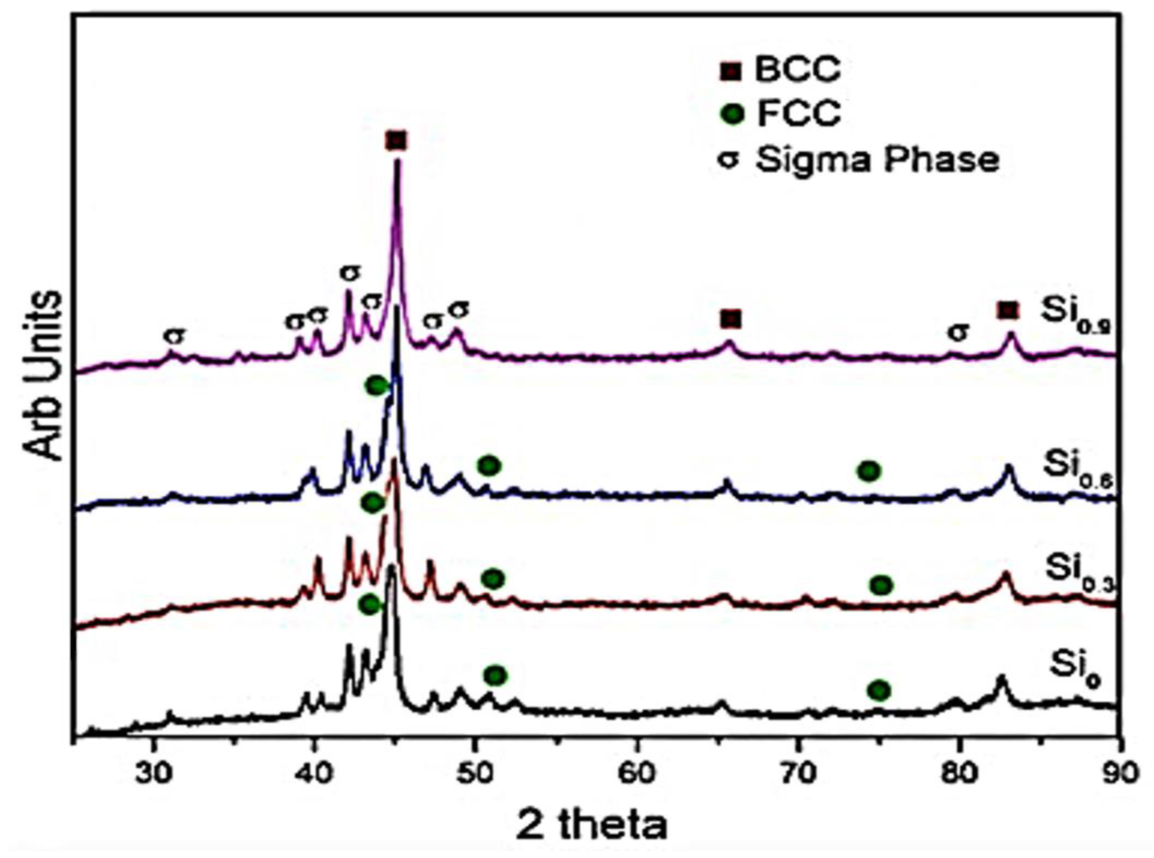
| AlCoCrFeNiSix (x = 0.3, 0.6, and 0.9) | S = 300 rpm | ST = 570–800 °C | BCC | BCC + FCC + sigma phase | [115] |
| HR = 100 °C min−1 | |||||
| BPR = 10:1 | ST = 800 °C–1000 °C | ||||
| D = 20 h | HR = 50 °C min−1 | ||||
| GM = tungsten carbide vial | (1000 °C in 5 min), | ||||
| P = 60 MPa | |||||
| Al0.4FeCrCo1.5NiTi0.3 | S = 300 rpm | ST = 1000 °C (10 min) | BCC + FCC | FCC (major) + BCC (minor) | [116] |
| BPR = 10:1 | |||||
| D = 50 h (dry) + 5 h (wet) | P = 30 MPa | ||||
| Al0.5CrFeNiCo0.3C0.2 | S = 300 rpm | ST = 600 °C (4 min) | BCC + FCC within first 38 h MA | FCC (major) + BCC | [117] |
| BPR = 10:1 | ST = 600–900 °C | ||||
| HR = 75 °C min−1 | |||||
| D = 38 h dry + 4 h wet (42 h) | ST = 900–1000 °C | ||||
| HR = 50 °C min−1 | |||||
| GM = stainless steel vial, tungsten carbide balls | (1000 °C in 8 min) | ||||
| P = 30 MPa | |||||
| CoCrFeNiMnAl | S = 250 rpm | ST = 800 °C (10 min) | BCC | BCC + FCC | [118] |
| BPR = 15:1 | |||||
| D = 60 h | P = 50 MPa | ||||
| Annealed from 500–1000 °C | |||||
| GM = stainless steel vial and balls, N-heptane PCA | |||||
| Ni1.5Co1.5CrFeTi0.5 | S = 250 rpm | ST = 1000 °C at HR = 100 °C min−1 | BCC + 2 FCCs | FCC + oxide | [119] |
| BPR = 10:1 | ST = 1000–1100 °C at HR = 50 °C min−1 | ||||
| D = 30 h dry + 2 h wet (toluene) (32 h) | ST = 1100–1150 °C at HR = 20 °C min−1 | ||||
| GM = hardened tool steel vial and hardened balls | (1150 °C in 20 min) | ||||
| P = 30 MPa | |||||
| AlCuNiFeCr | S = 580 rpm | ST = 700, 800, and 900 °C (15 min) | BCC | B2 + FCC + (Fe,Cr)23C6 after SPS | [120] |
| BPR = 1:10 | |||||
| D = 5 h | P = 150 MPa | ||||
| GM = hardened ShH-15 steel, gasoline medium | |||||
| Nb25Mo25Ta25W25 | S = 400 rpm | ST = 1600 °C (8 min) | BCC | BCC | [121] |
| BPR = 15:1 | |||||
| Ti8Nb23Mo23Ta23W23 | D = 60 h | P = 35 MPa | |||
| GM = tungsten carbide vials, acetone PCA | |||||
| CoNiFeAlTi | S = 300 rpm | ST = 1000 °C (8 min) | BCC + FCC | BCC (B2) + FCC + Al3Ti intermetallics after SPS | [122] |
| BPR = 10:1 | |||||
| D = 4 h wet + 45 h dry (49 h) | HR = 90 °C min−1 | ||||
| GM = stainless steel vials and tungsten carbide balls, no PCA | P = 30 MPa | ||||
| Al0.3CoCrFeMnNi | S = 200 rpm | ST = 800, 900, and 1000 °C (10 min), | FCC | BCC (B2) after SPS | [123] |
| BPR = 15:1 | HR = 100 °C min−1 | ||||
| D = 36 h | |||||
| GM = stainless steel vials and balls, N-heptane PCA | P = 50 MPa | ||||
| (CuCrFeTiZn)100-xPbx (x = 0, 5, 10, and 20) | S = 200 rpm | ST = 800, 900, and 1000 °C | Fe-Cr (BCC) + Cu-Zn (FCC) | Fe-Cr (BCC) + Cu-Zn (FCC) | [124] |
| BPR = 20:1 | |||||
| D = 44 h | HR = 150 °C min−1 | ||||
| GM = tungsten carbide vials and balls | P = 50 MPa | ||||
| HEA Composition | Processing Method | Observed Phase(s) | Microstructures and Comments | Reference |
|---|---|---|---|---|
| CoCrFeMnNi | Laser 3D printing | FCC (major) + BCC | An equiaxed-to-columnar transition structure was discovered in the melt pool. | [137] |
| CoCrFeMnNi | Laser powder bed fusion (LPBF) | FCC + σ phase | Nanotwins were present in the printed sample. | [146] |
| Mn segregates at the boundary of the weld pool due to its volatility. | ||||
| CoCrFeMnNi | Laser directed energy deposition | FCC solid solution | No phase transformation occurred | [147] |
| Lattice strain and grain refinement occurred. | ||||
| AlCrFeCoNi | Selective electron beam melting (SEBM) | FCC + BCC | Phase evolution occurred during the preheating process | [134,135] |
| AlCrFeCoMnNi | LPBF | BCC (B2, A2) | B2 (Ni-Al rich) and A2 (Fe-Cr rich) | [136] |
| Due to liquid-phase spinodal decomposition and cubic nature of the HEA | ||||
| Al0.3CoCrFeNi | LPBF | Supersaturated FCC phase | Fine columnar grains were present due to rapid solidification and anisotropic heat removal. | [139] |
| AlCoCrFeNiTi0.5 | Laser-engineered net shaping (LENS) | 2 BCC (B2, A2) | A fully equiaxed grain microstructure was exhibited rather than a columnar microstructure associated with alloys fabricated with AM. | [140] |
| AlCrCuFeNi | LPBF | 2 BCC (B2, A2) | Unique columnar grains were present containing multiple ultrafine sub-grain structures. | [145] |
| AlCrFeNiV | LPBF | FCC | Rapid cooling rate and solidification resulted in the formation of sub-grains in every columnar grain and L12 nano-phase. | [148] |
| AlCrFe2Ni2 | LPBF | BCC | Columnar BCC of spinodal decomposed B2 and A2 structures was exhibited. | [149] |
| Cracks were present at the intergranular site. | ||||
| FeCoCrNi | LPBF | FCC | After annealing at 1373 K, columnar grains and equiaxial grains were found to co-exist. | [150] |
| AlCoCrFeNi | Direct laser fabrication (DLF) | BCC (B2) | Intergranular needle-like and plate-like FCC phase precipitates and wall-shaped FCC phase precipitates were present along grain boundaries after aging at 800, 1000, and 1200 °C. | [151] |
| MoNbTaW | Direct energy deposition (DED) | BCC | [152] | |
| Al0.5Cr1.0Mo1.0Nb1.0Ta0.5 | SEBM | BCC | Two phases were present: TaMoNbCr and (TaMoNbCr)Al solid solutions. | [153] |
| CoCrCuFeNiAl | LENS | BCC (B2, A2) | Dendritic grains were present. | [154,155] |
| An ordered interface transition region was present between the two phases. | ||||
| AlCoCrFeNi2.1 | LENS | Ordered FCC (L12) + BCC | Co, Cr, and Fe stabilize L12. | [156] |
| L12 and BCC are rich in nickel. | ||||
| Fe38.5Mn20Co20Cr15Si5Cu1.5 | LPBF | FCC | Deformation-induced phase transformation of γ (FCC) to ε (HCP) occurred in the vicinity of microcracks. | [157] |
| CoCrFeNi | 3D extrusion printing | FCC | There was complex structural evolution, from loosely packed oxide particles in the green body to fully-annealed, metallic CoCrFeNi. | [158] |
| AlCrFeMoVx (x = 0 to 1) | LENS | BCC | The high solubility of V offers a broad range of solid solution strengthening of a compositionally complex but structurally simple BC matrix. | [158] |
| ZrTiVCrFeNi | LENS | C14 Laves phase (major) + α-Ti solid solution | The C14 Laves phase becomes stable on exposure to annealing and hydrogen influence. | [159] |
| 6FeNiCoSiCrAlTi | Laser cladding | BCC | Equiaxed polygonal grains, discontinuous interdendritic segregation, and nano-precipitates are present. | [160] |
| MoFeCrTiW | Laser cladding | BCC | Cellular crystals are formed on which dispersion precipitates exist. | [161] |
| TiZrNbMoV | LENS | FCC (δTiHx-type) + BCC (NbH∼0.4–type) | αZr-rich precipitates are present, in addition to the phases formed. | [162] |
| Al0.5FeCu0.7NiCoCr | Laser cladding | FCC + BCC + Al phases | A laser rapid cooling rate facilitates the formation of a simple structure and prohibits the formation of undesired intermetallic compounds. | [163] |
| TiZrNbHfTa | Laser metal deposition (LMD) | BCC | An equiaxed grain shape is present. | [164] |
| Al0.5CrMoNbTa0.5 | Electron beam melting (EBM) | BCC | Intermetallic phases C14, C36, C15, and 6H are present. | [165] |
| Ni6Cr4WFe9Ti | LPBF | FCC | Tiny precipitates of an unknown phase are present. | [166] |
| FeCoCrNiC0.05 | LPBF | FCC | Nano-scale Cr23C6-type carbides can precipitate under annealing conditions. | [167] |
| HEA Composition | Observed Phase(s) through Different Processing Route(s) | Strengthening Mechanism in Respective Processing Route(s) | Effects on Mechanical Properties | ||||||
|---|---|---|---|---|---|---|---|---|---|
| Melting and Casting | MA + SPS | AM | Melting and Casting | MA + SPS | AM | Melting and Casting | MA + SPS | AM | |
| CoCrFeNiMn | FCC [11,46] | FCC [192] | FCC + BCC [137,146,147] | Solid solution strengthening | Grain boundary strengthening | Compressive strength of 1987 MPa | Tensile strength of 601 MPa | ||
| Hardness of 646 HV | |||||||||
| CoCrFeNiAl0.3 | FCC [68,69] | FCC + BCC [112] | FCC [139] | Grain boundary strengthening | Solid solution strengthening | Dislocation hardening | UTS of 528 MPa | Compressive strength of 1907 MPa | YS of 730 MPa |
| YTS of 275 MPa | Hardness of 625 HV | UTS of 896 MPa | |||||||
| CoCrFeNi | FCC + Cr7C3 [23] | FCC [150] | Grain boundary strengthening (470 HV), precipitation strengthening | Hardness of 580 HV | |||||
| AlCoCrCuFeNi | FCC + BCC [64] | FCC + BCC [189] | BCC [154] | Solid solution strengthening | Grain boundary strengthening, solid solution strengthening | Hardness of 515.5 HV (5.056 GPa) | Hardness of 8.13 GPa | ||
| Compressive strength of 1.82 GPa | Elastic modulus of 172 GPa | ||||||||
| TiZrNbMo0.3V0.3 | BCC [193] | FCC + BCC [162] | Solid solution strengthening | Yield strength of 1312 MPa and 50% increase in plastic strain | |||||
| Ni1.5Co1.5CrFeTi0.5 | FCC [48] | FCC [119] | Solid solution hardening | Grain boundary strengthening | YS of 896 MPa | Hardness of 442 HV0.3 | |||
| Compressive strength of 1502 MPa | Tensile strength of 1384 MPa | ||||||||
| Hardness of 515 HV | Elastic modulus of 216 GPa | ||||||||
| Al0.7FeCoCrNi1.3 | FCC + BCC [172] | Precipitation strengthening by the B2 NiAl phase in an Fe-Cr-Ni matrix | A good compromise between hardness (280 HV) and strength | ||||||
| Grain boundary precipitation of the Ni-Al-rich phase | |||||||||
| (FeCoNiCr)94Ti2Al4 | FCC [168] | Precipitation hardening (327.7 MPa), dislocation hardening (274.5 MPa), | Accumulated yield strength of 645 MPa | ||||||
| grain boundary hardening (122.6 MPa) | |||||||||
| CuCr2Fe2NiMn | FCC [59] | Precipitation hardening of the ρ phase | Hardness of 450 HV | ||||||
| FeCrNiCoMn | FCC [194] | Grain boundary strengthening | Increase in yield strength from 200 to 350 MPa | ||||||
| Al0.3CrFe1.5MnNi0.5 | FCC + BCC [56] | Precipitation hardening | Hardness of 800 HV | ||||||
| Ni2CoCrFeNb0.15 | FCC [170] | Precipitation strengthening (670 MPa), solid solution hardening (41.7 MPa) | Total yield strength of (954 MPa) | ||||||
| Ductility (27%) | |||||||||
| Excellent yield strength–ductility combination | |||||||||
| Al0.5CrFeNiCo0.3C0.2 | FCC + BCC [117] | Solid solution strengthening | Compressive strength of 2131 MPa | ||||||
| Hardness of 617 ± 25 HV | |||||||||
| CoCrFeNiMo0.3 | FCC [195] | Precipitation hardening | Tensile strength of 1.2 GPa and good ductility of ∼19% | ||||||
| FeCoCrNiMnTi0.1C0.1 | FCC [196] | Grain boundary strengthening (61.3%), | Yield strength of 1652 MPa | ||||||
| precipitation strengthening (20.6%), | Hardness of 461 HV | ||||||||
| dislocation strengthening (15.0%) | |||||||||
| Co25Ni25Fe25Al7.5Cu17.5 | FCC [197] | Grain boundary strengthening, | Compressive yield strength of 1795 MPa | ||||||
| dislocation strengthening | Hardness of 454 HV | ||||||||
Publisher’s Note: MDPI stays neutral with regard to jurisdictional claims in published maps and institutional affiliations. |
© 2021 by the authors. Licensee MDPI, Basel, Switzerland. This article is an open access article distributed under the terms and conditions of the Creative Commons Attribution (CC BY) license (https://creativecommons.org/licenses/by/4.0/).
Share and Cite
Onawale, O.T.; Cobbinah, P.V.; Nzeukou, R.A.; Matizamhuka, W.R. Synthesis Route, Microstructural Evolution, and Mechanical Property Relationship of High-Entropy Alloys (HEAs): A Review. Materials 2021, 14, 3065. https://doi.org/10.3390/ma14113065
Onawale OT, Cobbinah PV, Nzeukou RA, Matizamhuka WR. Synthesis Route, Microstructural Evolution, and Mechanical Property Relationship of High-Entropy Alloys (HEAs): A Review. Materials. 2021; 14(11):3065. https://doi.org/10.3390/ma14113065
Chicago/Turabian StyleOnawale, Omoyemi Temitope, Prince Valentine Cobbinah, Rivel Armil Nzeukou, and Wallace Rwisayi Matizamhuka. 2021. "Synthesis Route, Microstructural Evolution, and Mechanical Property Relationship of High-Entropy Alloys (HEAs): A Review" Materials 14, no. 11: 3065. https://doi.org/10.3390/ma14113065