1. Introduction
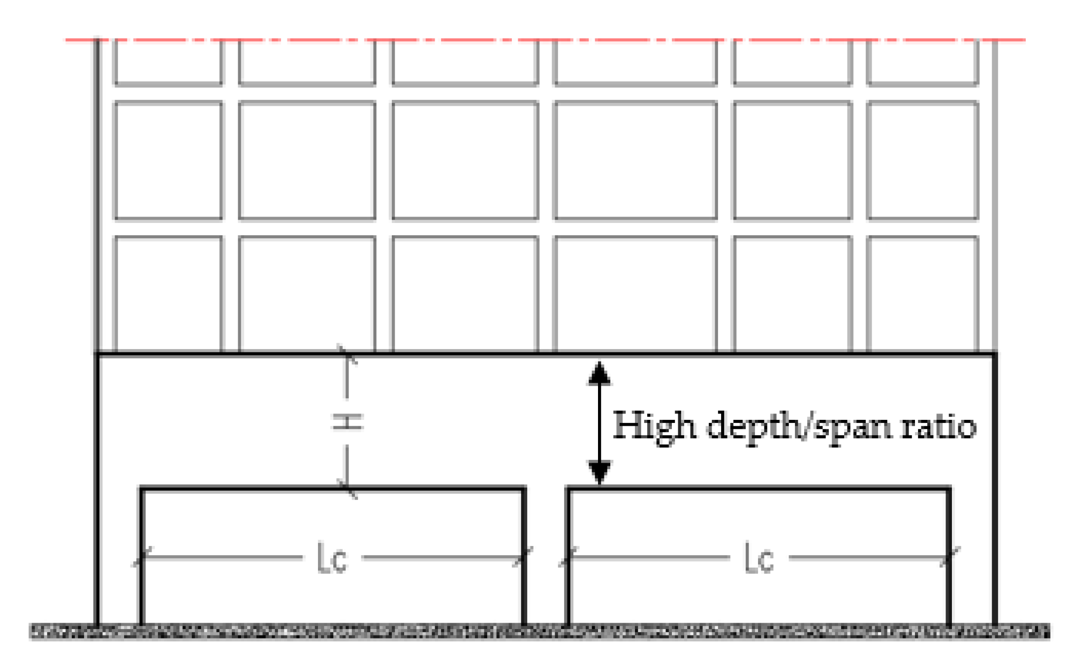
Deep beams are defined as beams with a clear span (L
c) to overall depth (H) ratio that is less than or equal to four [
1]. In the structural engineering industry, reinforced concrete continuous deep beams (RCCDBs) are a subject of great interest. Transfer girders, pile caps, tanks, folded frames, and foundation walls are some examples of RCCDBs that carry several small loads and pass them to a small number of reaction points [
2,
3].
Figure 1 illustrates RCCDBs with high span/depth ratios.
Openings in the web of RCCDBs are commonly used to facilitate important utilities, such as air conditioner ducts and electricity cables, and to provide functionality, such as doors and windows [
2]. These openings can be defined as small or large openings based on the ratio of the web opening depth (h
o) to the total depth of the section (H). If this ratio is less than 25%, the opening might be considered a small opening [
4]. Providing openings could result in significant reductions in strength and stiffness, which could also lead to significant safety risks. Therefore, strengthening techniques can be used to recover and regain the beam strength due to openings. External strengthening using CFRP strips is considered an appropriate strengthening technique [
5]. The greatest benefits of using CFRP strips are lightweight, high-strength, speed, ease of application, and the ability to form different shapes on-site.
Previous research studies have been conducted on the behavior and strengthening of simply supported reinforced concrete deep beams with and without openings [
6,
7,
8,
9,
10,
11,
12,
13]. The creation of rectangular and circular openings in shear spans of the reinforced concrete deep beams affect the load-carrying capacity, where the reduction of the failure load reached 66% [
6,
8]. The ultimate capacity of simply supported reinforced concrete deep beams was not influenced by the opening if the depth of the top chord was more than or equal to the depth of the concrete stress block at the ultimate state when the openings were in the pure flexure zone [
9]. Symmetrical, unsymmetrical, and centered web openings were investigated through load-deflection curves, crack patterns, and absorbed energy [
13]. Vertical and inclined U-wrapped schemes were used to strengthen the deep beams around the openings [
7,
8,
9,
10]. Using inclined strips of CFRP was more effective in upgrading the stiffness and shear strength of deep beams [
8,
10]. The addition of horizontal CFRP strips to the system of vertical CFRP strips added improvement in the ultimate strength [
10]. Moreover, the most effective number of CFRP layers was investigated for reinforced concrete simply supported deep beams with large openings in the shear zone. Two and three layers were the most effective for opening sizes of 150 and 200 mm, respectively [
11].
An advanced nonlinear FE model was used to understand the behavior of deep beams retrofitted with fiber-reinforced polymer (FRP) sheets [
12]. The crack formation and propagation in epoxy were predicted by incorporating a moving mesh modeling. The debonding mechanism was modeled using interface elements [
14]. The CFRP sheets were modeled using Shell elements with multilayers including the adhesive layer. This adhesive layer was considered the bond between the CFRP sheets and concrete [
15]. Increasing numbers of CFRP layers effectively enhanced the load-carrying capacity [
11].
On the other hand, different strengthening techniques were investigated for the RCCDBs. These techniques included steel reinforced grout, a fabric-reinforced cementitious matrix, and external pre-stressed strands [
16,
17,
18]. The bond of the steel-reinforced grout system was influenced by the curing time and the ultimate capacity was linearly increased with the age of the composite [
16]. The shear strength was improved by using the fabric-reinforced cementitious matrix but not proportionally to the number of fabric plies installed [
17]. However, the physical properties of using CFRP laminates provided an effective choice as a strengthening technique [
5].
Most of the previous studies focused on strengthening of simply supported reinforced concrete deep beams and there are limited reported works (up to date) related to the application of CFRP strips, as a strengthening technique, for RCCDBs with large openings. Therefore, this paper aims to investigate experimentally and numerically the effectiveness of using carbon fiber reinforced polymer (CFRP) strips to externally strengthen reinforced concrete continuous deep beams (RCCDBs) with large openings. The experimental work included testing three RCCDBs under five-point bending. A reference specimen was prepared without openings to explore the reductions in strength and stiffness after providing large openings. Openings were created symmetrically at the center of spans of the other specimens to represent 40% of the overall beam depth. Moreover, finite elements (FE) analysis was validated using the experimental results to conduct a parametric study on RCCDBs strengthened with CFRP strips.
4. Finite Element Analysis
The geometric and material non-linearity simulation of RCCDBs with and without openings was presented by proposing a FE model, using ABAQUS [
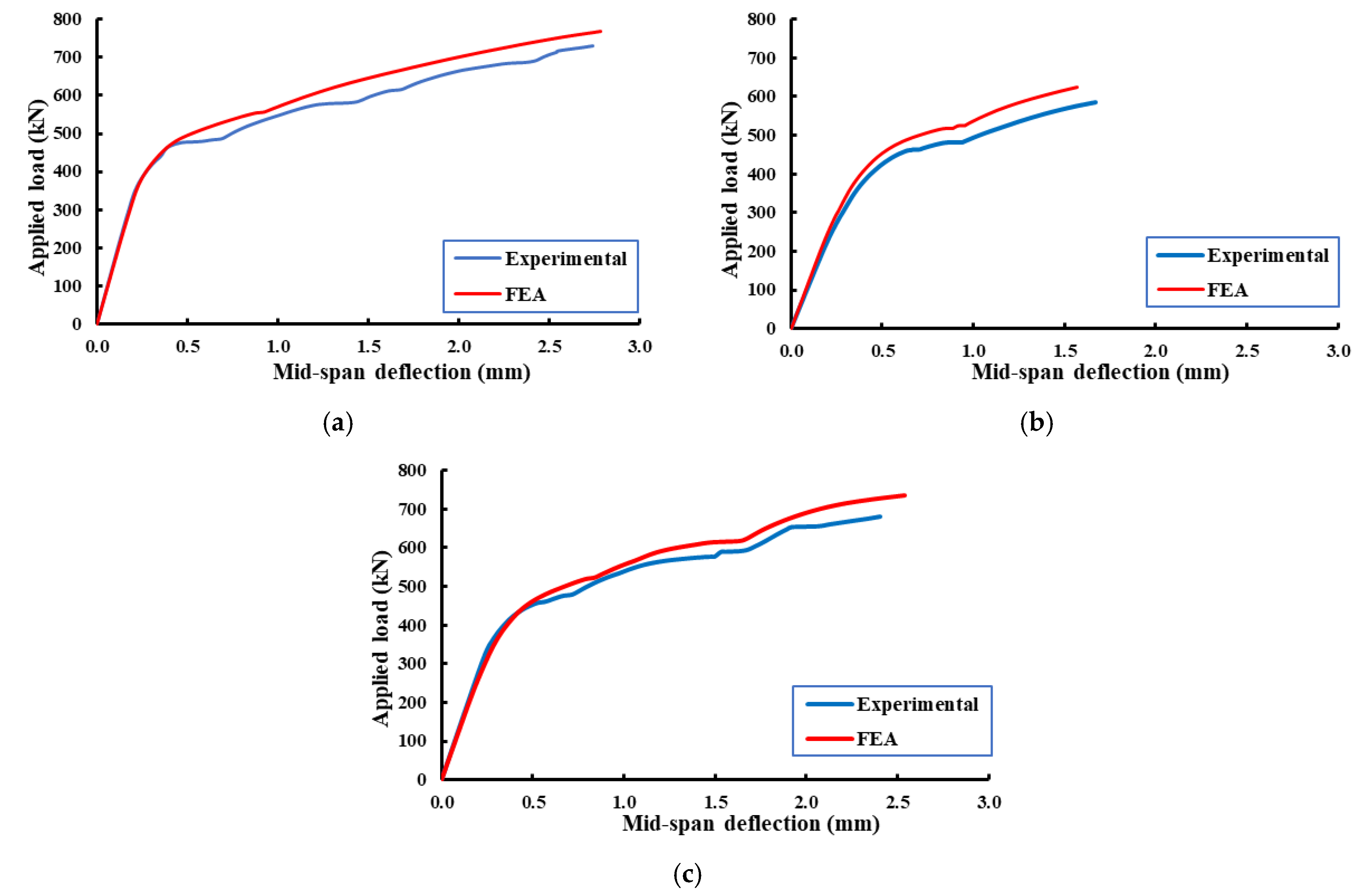
19]. The proposed model was validated using the test findings presented in this paper. Moreover, an extensive parametric study was carried out to represent an important benchmark to predict the full static resistance of RCCDBs with openings under the effect of different parameters.
4.1. Constitutive Models of Materials
The concrete damage plasticity (CDP) model, which is available in ABAQUS, was used to simulate the concrete behavior [
19]. This model requires the concrete compressive and tensile composition relation, damage parameters for cracking and crushing and other parameters of material such as dilation (φ), eccentricity (ε), compressive strength to uniaxial pressure ratio biaxial (
), coefficient K, and viscosity parameters (μ) [
20].
Table 5 lists the different parameters that were established from previous analyses and implemented in this study. The stress–strain relationship in compression that was proposed by Saenz [
21] was adopted in this research and is illustrated in
Figure 8a. On the other hand, the stress–strain relationship of concrete in tension was determined by using the exponential function proposed by Belarbi and Hsu [
22] and is illustrated in
Figure 8b.
The bilinear model, which is adopted in ABAQUS, was used to simulate the behavior of steel reinforcement, shrinkage reinforcement, and stirrups. For the linear isotropic part, it is defined by the modulus of elasticity of the reinforcement and the Poisson’s ratio, which are taken as 200 × 10
3 MPa and 0.3, respectively, and away from this point, it plasticized perfectly, which was defined by the yield stress f
y. However, a linear model was used to represent the stress–strain relationship for the CFRP laminates. This relationship was defined by the modulus of elasticity and tensile strength, which were provided by the manufacturer. The CFRP composites were treated as an orthotropic material by considering the direction of fibers as the main direction. The mechanical properties used in the FE simulation are listed in
Table 2.
4.2. Element Type and Meshing Scheme
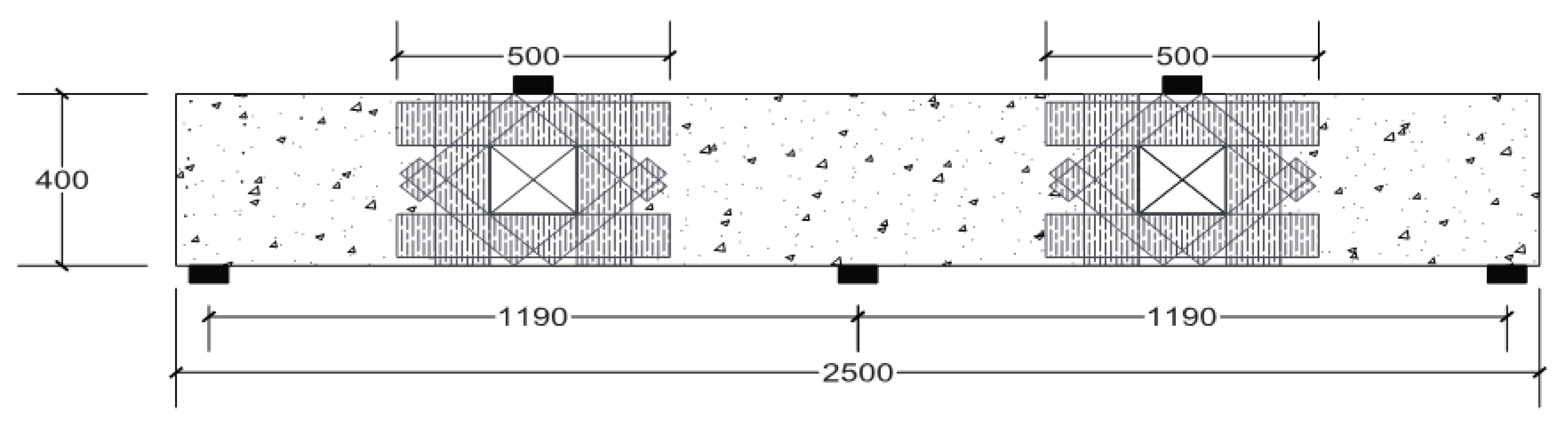
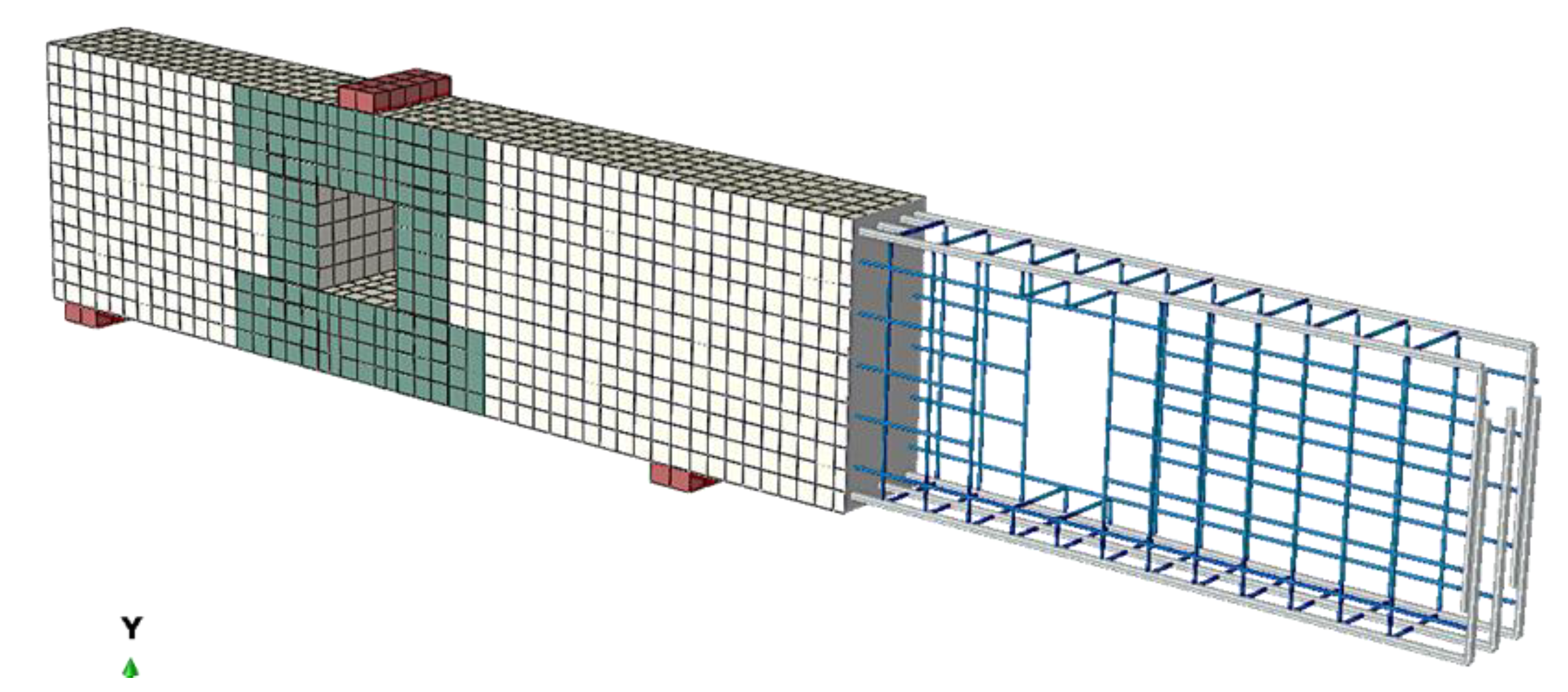
Concrete was idealized by using a solid element, C3D8, which has the capability of cracking in tension and crushing in compression. The steel rebars are simulated by using a three-dimensional truss element (T3D2). A 4-node shell element (S4) was used to simulate the CFRP strips. The used plates at supports and loading points were modeled using the solid finite element in ABAQUS. Many trials with different mesh sizes were carried out to improve the FE and avoid the in-convergence issues. Finally, cubes with maximum dimensions of 30 mm × 30 mm × 30 mm for concrete and squares of 30 mm × 30 mm for the CFRP strips were used in the mesh of the analyzed beams. The mesh geometry, loading arrangement of the FE model, CFRP strips, and details of the steel reinforcement are presented in
Figure 9.
4.3. Boundary Conditions
The boundary conditions were modeled as a contentious beam, which was the same as those of the test setup. At one of the supports, the translation degrees of freedom were constrained in X and Y directions, which represented hinged support. In contrast, the translational degrees of freedom were constrained only in the Y direction for the other two supports, which represented roller supports.
The steel reinforcements were embedded inside the solid concrete elements with a perfect bond connection. Moreover, the full bond connection was assumed between the two surfaces of concrete and CFRP strips. The contact between the concrete surfaces and steel plates was assigned as tie constraints. The translational and rotational motion, as well as all other active degrees of freedom, were equal.
6. Parametric Study
6.1. Effect of the Ratio of the Opening Dimensions
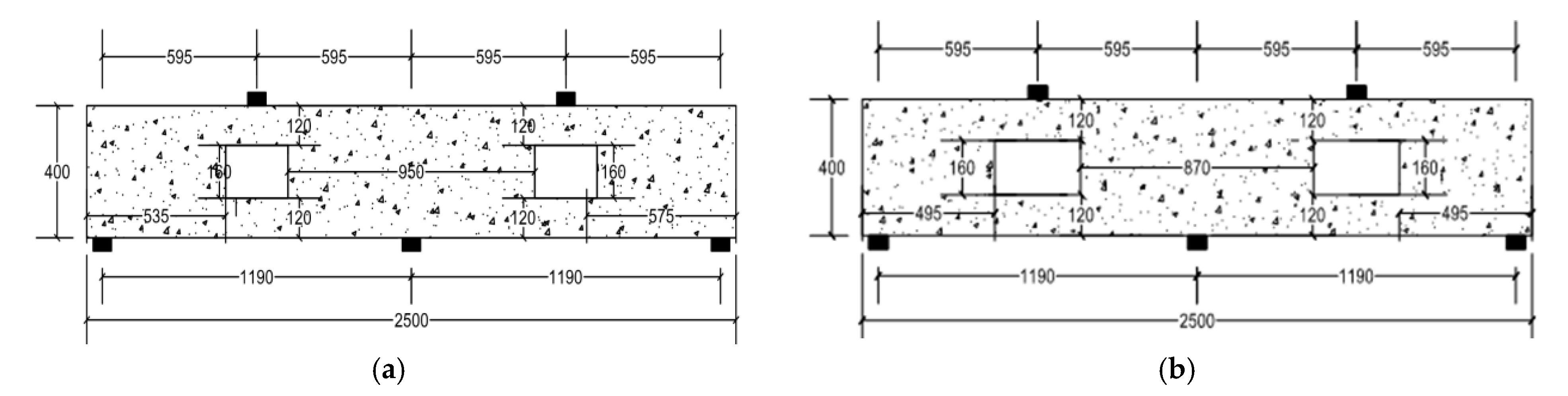
The ratio of the opening dimensions is defined as the length of the opening divided by the depth of the opening. In this parametric study, the ratios of the opening dimensions were chosen to be 1.0, 1.5, and 2.0 (i.e., opening length = 160, 240, and 320 mm). The opening depth was kept constant at 160 mm for comparison purposes. Each model was analyzed with and without CFRP strips to explore the effect of adding this strengthening technique on the overall behavior of RCCDBs with openings of different dimensions. Descriptions and details of the newly analyzed beams with opening ratios 1.5 and 2.0 are shown in
Figure 12.
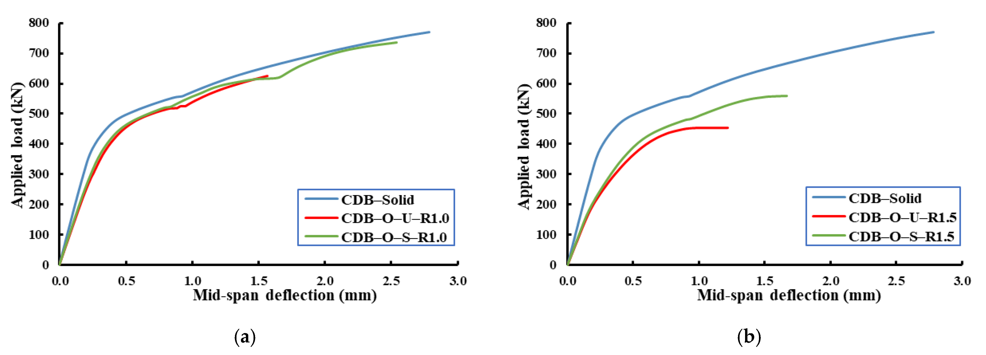
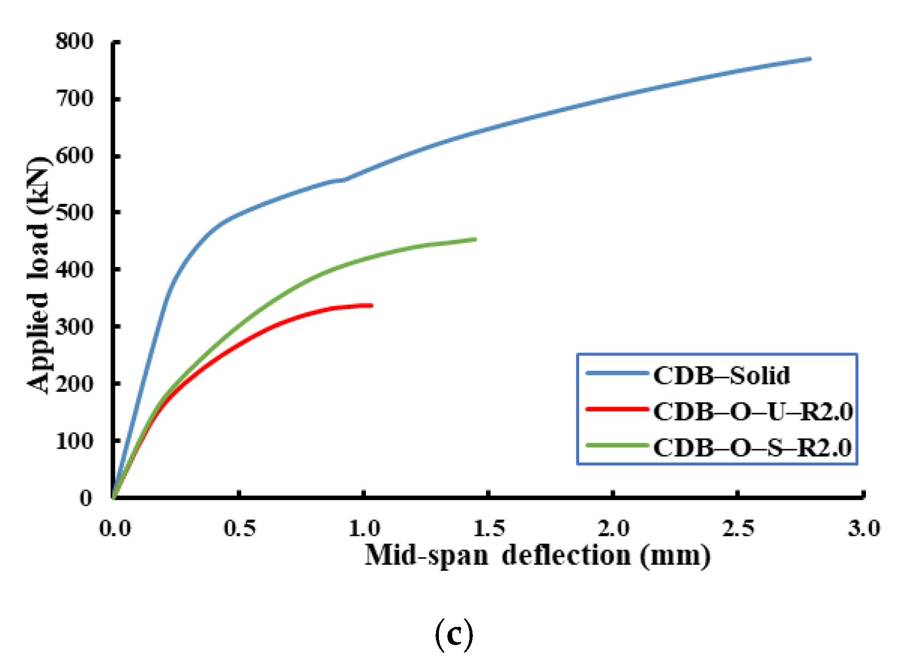
Figure 13 shows the effect of using openings with different dimensions ratios on the behavior of strengthened and un-strengthened RCCDBs relative to the solid beam (CDB–Solid). It was clear that as the opening ratio increased, the ultimate capacity was reduced, and the mid-span deflection was increased. Moreover,
Table 7 summarizes these effects on the ultimate capacities and mid-span deflections. The percentages of improvements in the beam capacity and deflection for the strengthened beams were calculated corresponding to the un-strengthened one with the same opening ratio. The ratio of the opening dimensions affected the effectiveness of using CFRP strips as a strengthening technique for RCCDBs with openings. The ultimate capacity and mid-span deflection of the strengthened beam were improved as the ratio of the opening dimensions increased relative to the un-strengthened one (see
Figure 14). The ultimate loads were increased by 18%, 23%, and 35% for beams with an opening ratio of 1.0, 1.5, and 2.0, respectively. In contrast, the mid-span deflections were decreased by 7%, 23%, and 40% for beams with ratios of the opening dimensions of 1.0, 1.5, and 2.0, respectively.
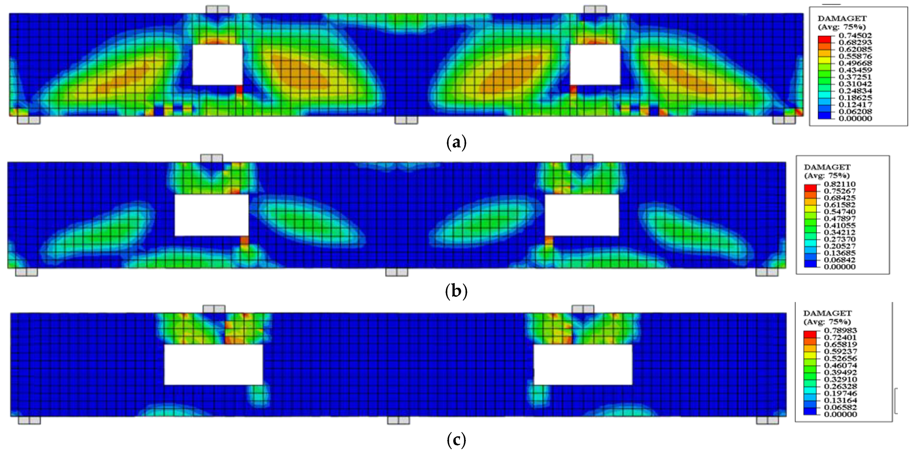
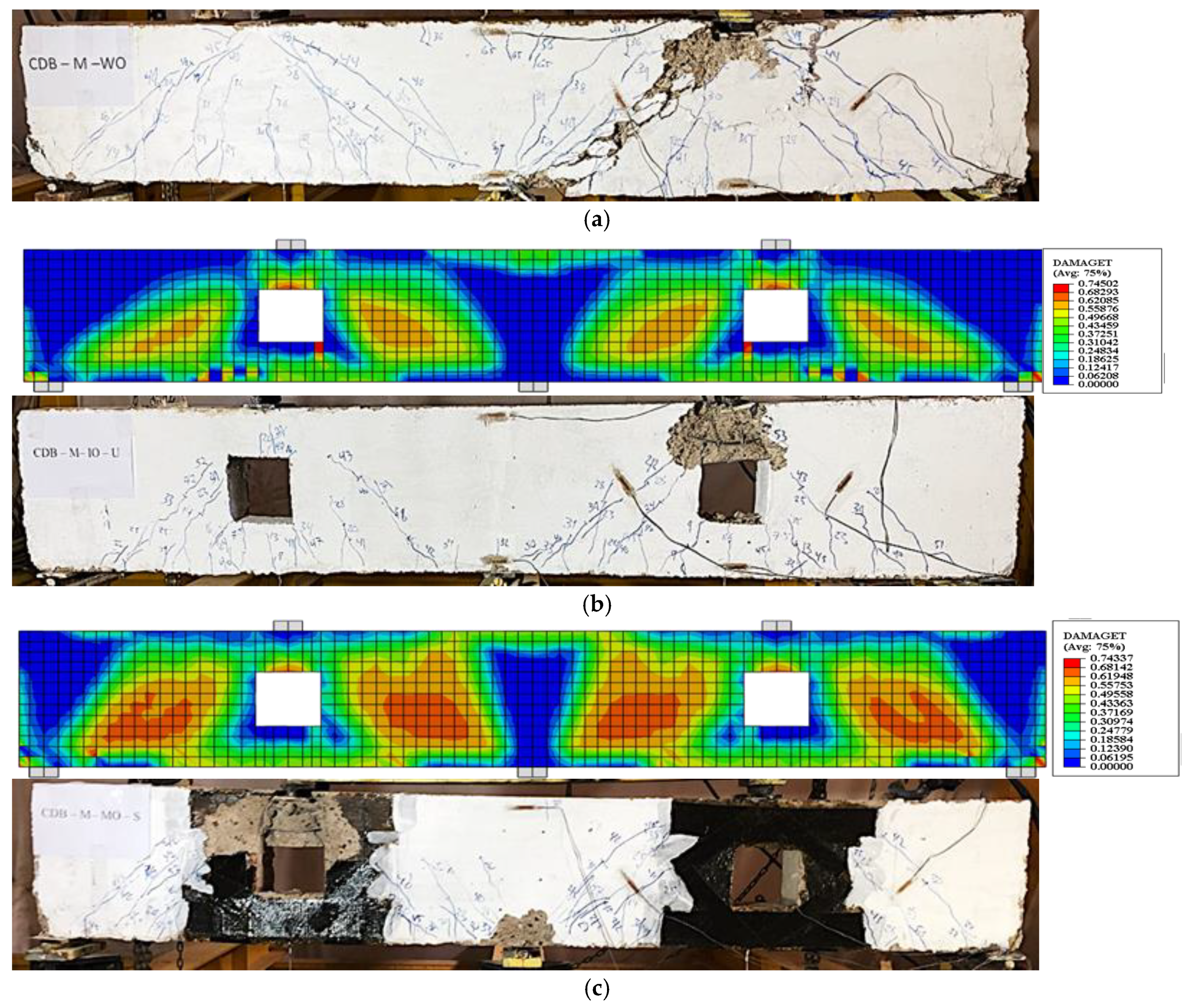
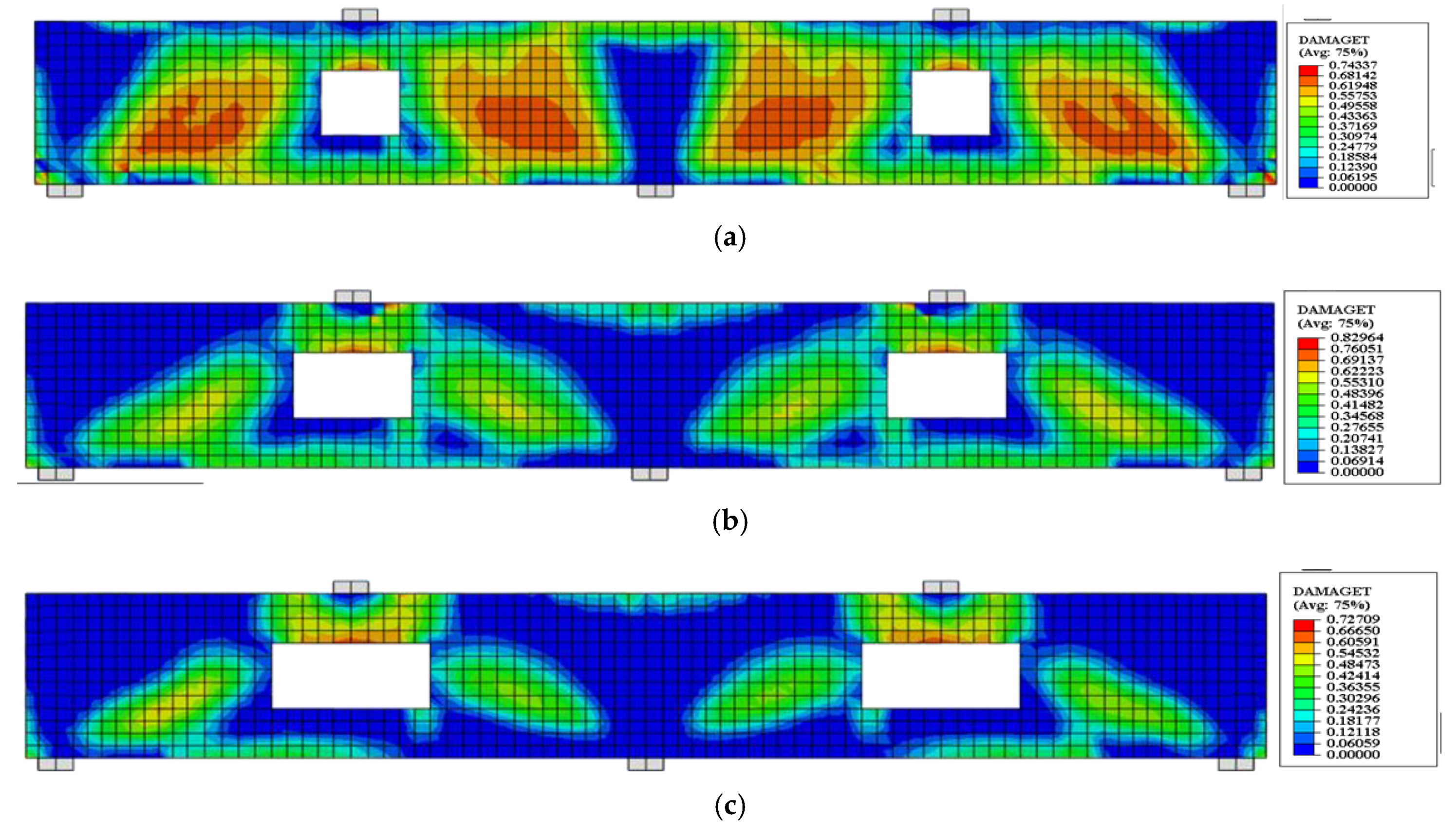
Figure 15 and
Figure 16 show the effect of the ratios of the opening dimensions on the FE crack pattern of un-strengthened and strengthened beams. It was obvious that as the ratio of the opening dimensions increased, the concrete damage increased around the perimeter of the openings. Therefore, the effectiveness of using CFRP strips as a strengthening technique around these openings increased.
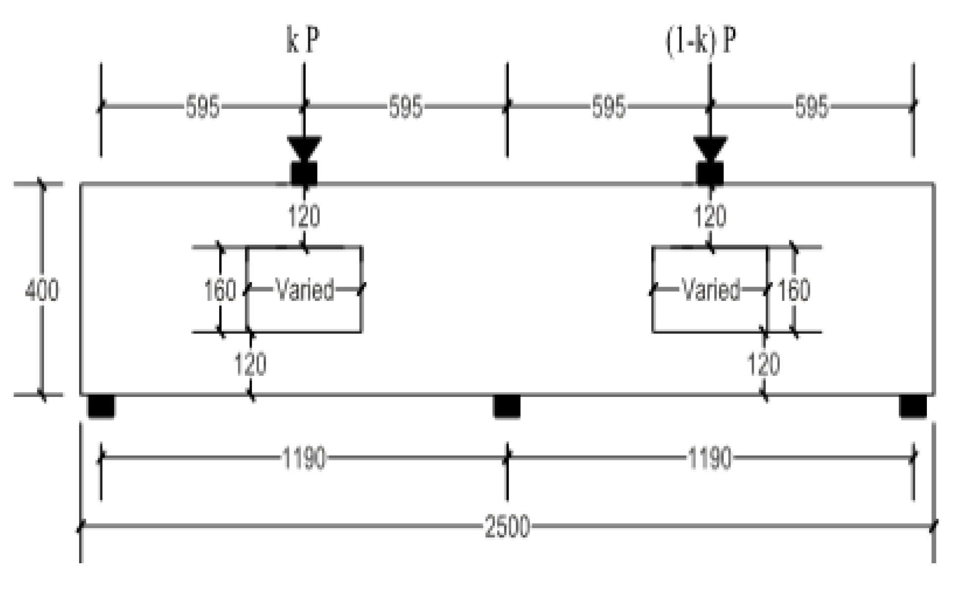
6.2. Effect of Load Distribution Factor
Another parameter was adopted in this section, which concerns the effect of load distribution factor (k) on the behavior of un-strengthened and strengthened RCCDBs with large openings. The load distribution factor (k) refers to the ratio of a single-span applied load to the total load (see
Figure 17). In the present study, this factor was set as 0.25, 0.30, and 0.40, as listed in
Table 8.
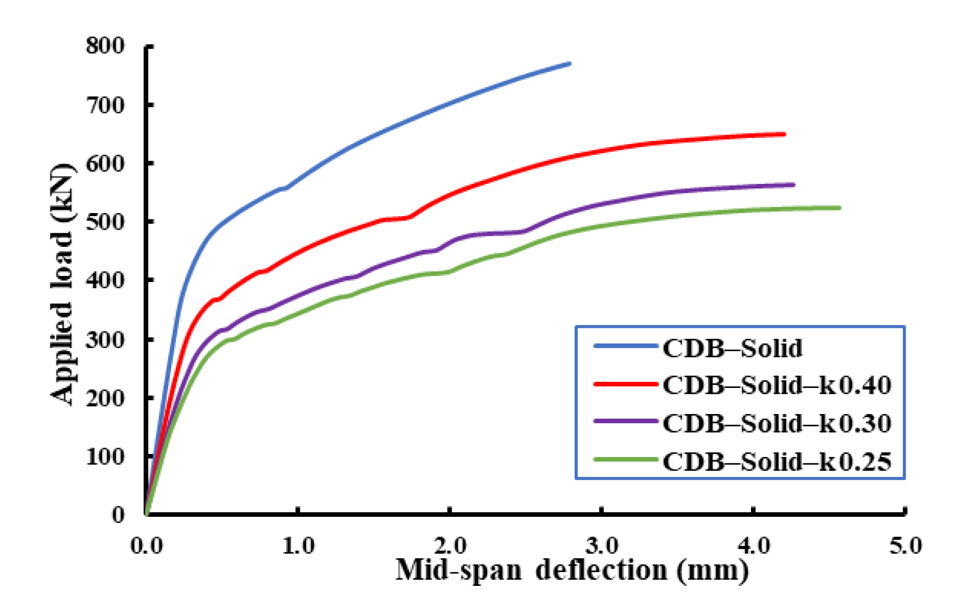
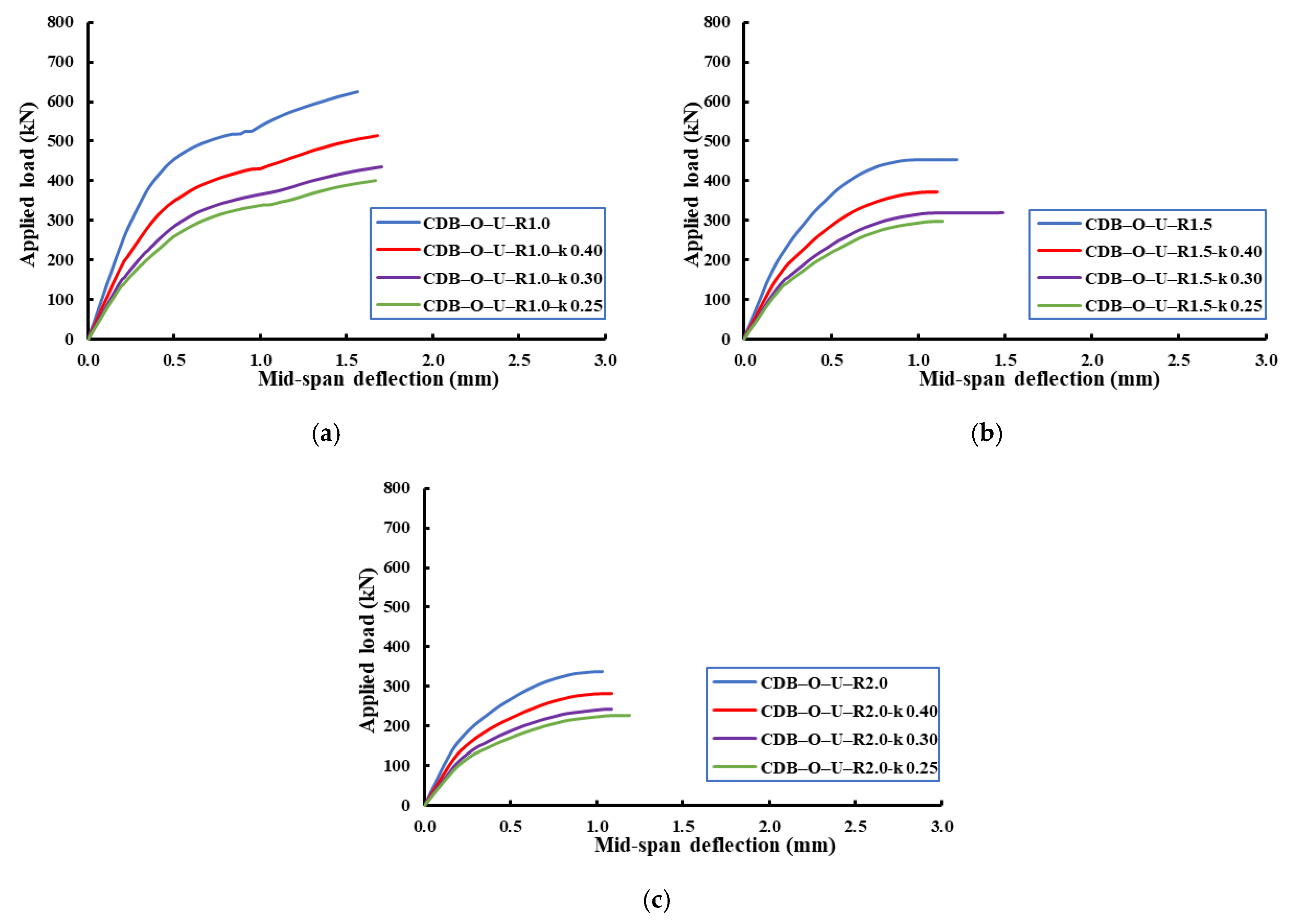
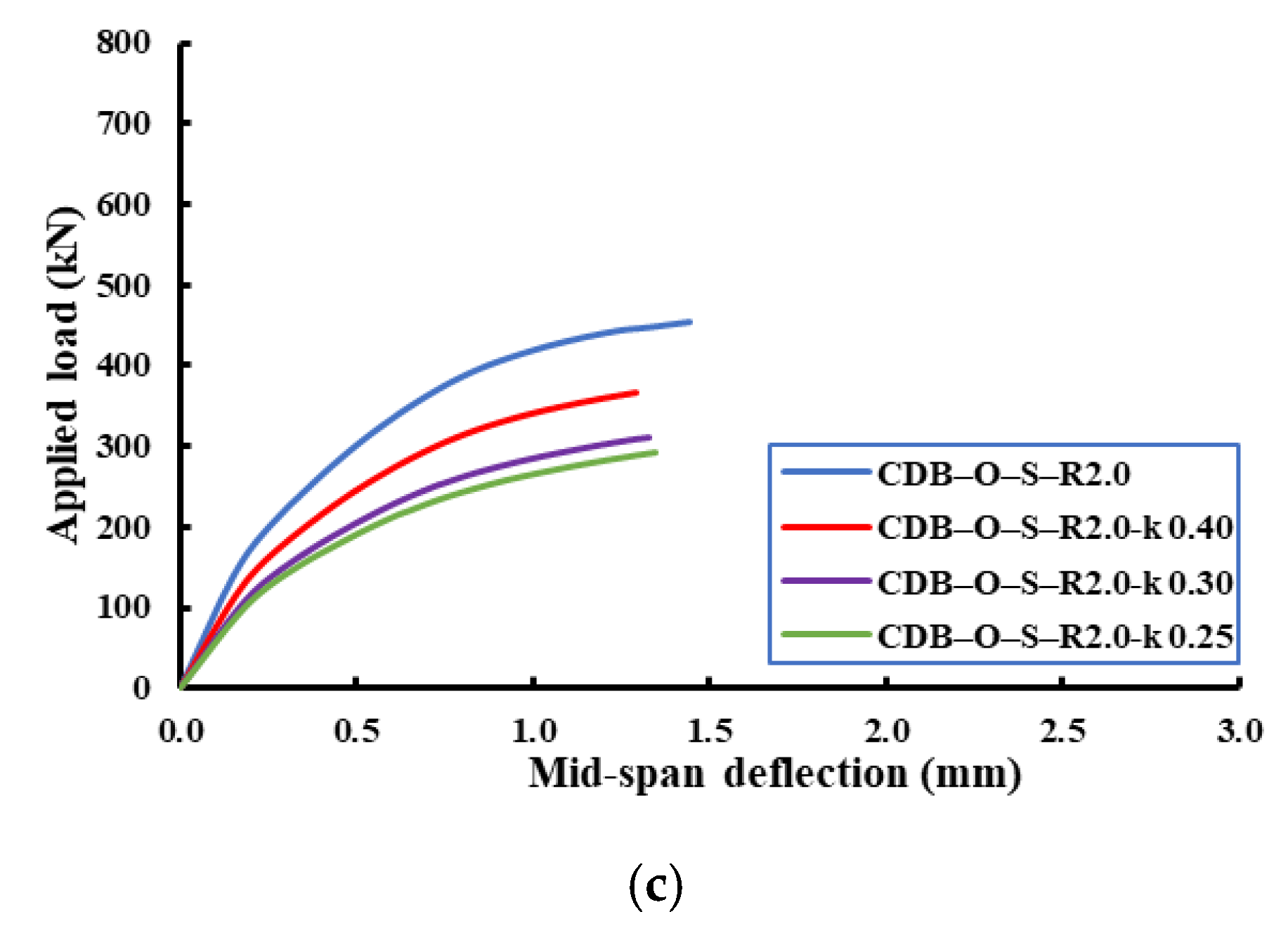
Figure 18,
Figure 19,
Figure 20 show the effect of the load distribution factor (k) on the load–deflection relationship of the analyzed beams. The data presented in these figures were for the applied load and mid-span deflection for the critical span (i.e., the span under the applied load of (1-k) of the total load). From these figures, it can be noticed that the decreasing of load distribution factor from 0.4 to 0.25 led to reductions in the ultimate capacity and an increase in the ultimate deflection compared to the beam with an equal load distribution factor (i.e., k = 0.5).
Table 8 summarizes ultimate capacities and mid-span ultimate deflections for the analyzed beams.
For the strengthened beams with an opening ratio of 1.0, the reductions in the ultimate capacity were 18%, 32%, and 36% for load distribution factors of 0.4, 0.3, and 0.25, respectively, relative to the reference beam for this category (CDB–O–S–R1.0 with k = 0.5). In contrast, the percentage increase in mid-span ultimate deflections of these beams were 117%, 312%, and 371%, respectively.
For the strengthened beams with an opening ratio of 1.5, the reductions in the ultimate capacities were 18%, 31%, and 36% for load distribution factors of 0.4, 0.3, and 0.25, respectively, relative to the reference beam of this category (CDB–O–S–R1.5 with k = 0.5). However, the percentage increase in mid-span ultimate deflections of these beams were 62%, 171%, and 245%, respectively.
For the strengthened beams with an opening ratio of 2.0, the reductions in the ultimate capacity were 19%, 31%, and 36% for load distribution factors of 0.4, 0.3, and 0.25, respectively, relative to the reference beam of this category (CDB–O–S–R2.0 with k = 0.5). In contrast, the percentage increase in mid-span ultimate deflections of these beams were 46%, 121%, and 179%, respectively.
From these results, it can be noticed that the decreasing of load distribution factor from 0.4 to 0.25 led to the same trend of reduction in the ultimate capacities and increase in the ultimate deflections compared to the beams with an equal load distribution factor (i.e., k = 0.5).
7. Conclusions
The effectiveness of using CFRP strips was investigated experimentally and numerically to externally strengthen RCCDBs with large openings. The experimental work included testing three RCCDBs under five-point bending. Moreover, FE analysis was validated using the experimental results to conduct a parametric study on RCCDBs strengthened with CFRP strips. The following conclusions can be drawn from this research work.
1. Using CFRP strips restored part of the reduced capacity by 17% and decreased the mid-span ultimate deflection by 10% relative to the un-strengthened beam.
2. It was observed that using CFRP strips led to an increase in the first crack load by 5% and 50% relative to the solid and un-strengthened specimens, respectively.
3. The ratio of the opening dimensions affected the effectiveness of using CFRP strips as a strengthening technique for RCCDBs with openings. The ultimate capacity and mid-span deflection of the strengthened beam were improved as the opening ratio increased relative to the un-strengthened one.
4. The existence of CFRP strips had a minor effect on controling the behavior of RCCDBs with different load distribution factors. Reductions in the ultimate capacity and increase in the mid-span ultimate deflection were obtained as the load distribution factor decreased from 0.5 to 0.25.
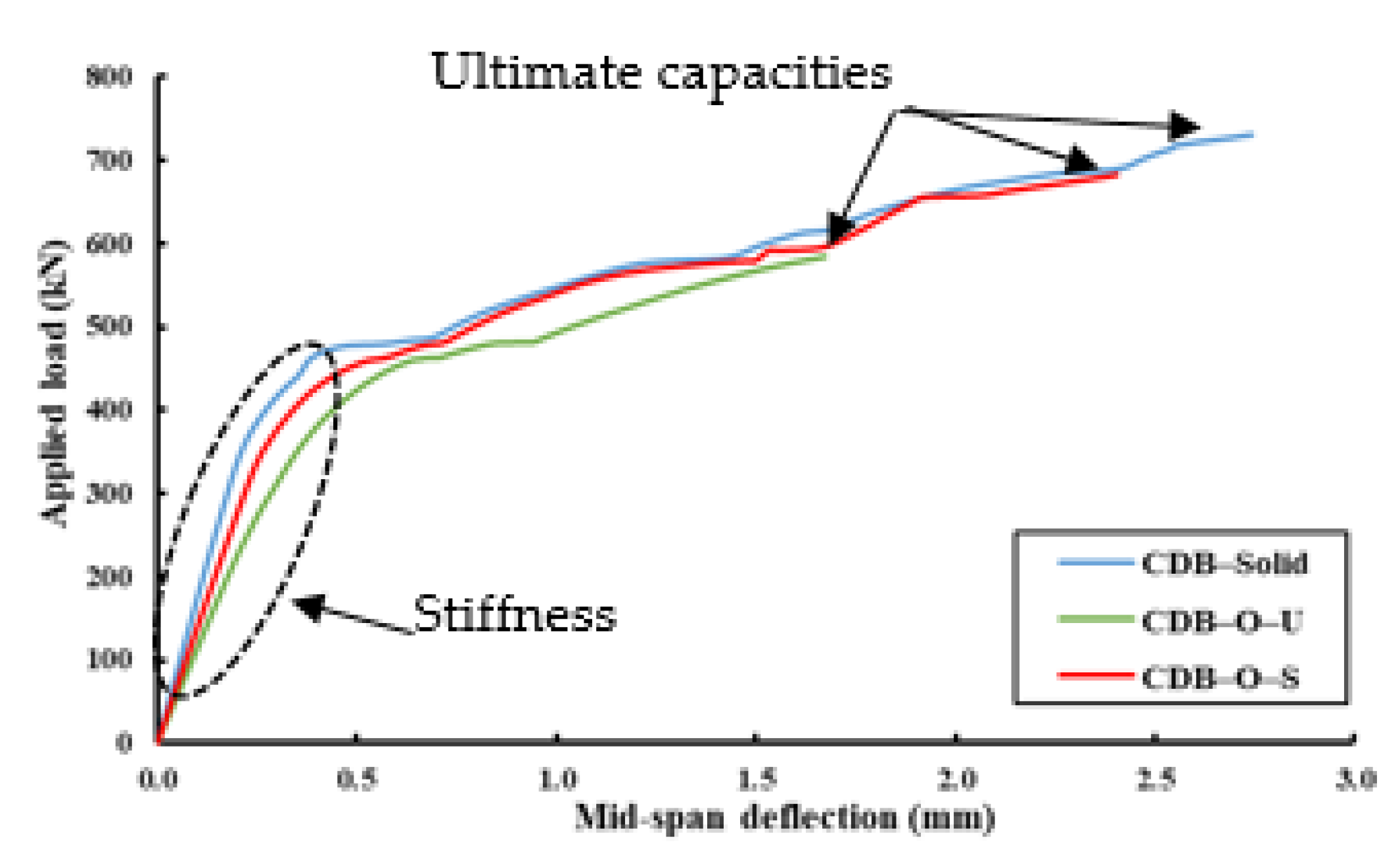
5. The presence of large openings in RCCBDs led to reductions in the ultimate capacity by about 21% and initial stiffness by about 35%, and an increase in the mid-span ultimate deflection by about 21% was obtained compared to the solid beam.


 ,
, 


