Abstract
The re-entrant structures are among the simple unit cell designs that have been widely used in the design of mechanical metamaterials. Changing the geometrical parameters of these unit cell structures, their overall elastic properties (i.e., elastic stiffness and Poisson’s ratio), can be simultaneously tuned. Therefore, different design strategies (e.g., functional gradient) can be implemented to design advanced engineering materials with unusual properties. Here, using the theory of elasticity and finite element modeling, we propose a fast and direct approach to effectively design the microarchitectures of mechanical metamaterials with re-entrant structures that allow predicting complex deformation shapes under uniaxial tensile loading. We also analyze the efficiency of this method by back calculating the microarchitectural designs of mechanical metamaterials to predict the complex 1-D external contour of objects (e.g., vase and foot). The proposed approach has several applications in creating programmable mechanical metamaterials with shape matching properties for exoskeletal and soft robotic devices.
1. Introduction
Cellular materials (e.g., bone, wood, and cork) can be extensively found in nature. These natural cellular materials have been sources of inspiration for engineers for many decades to create bioinspired lattice structures [1], for instance, those with low density and high stiffness [2] or high energy absorption properties [3]. Design motifs, such as hierarchy and functional gradient, are examples of design principles that exist broadly in natural materials and have been widely used to develop bio-inspired cellular structures [4,5]. The re-entrant unit cells are among those cellular microstructures that found their roots in nature and have been utilized to design advanced engineering materials, such as designer materials or mechanical metamaterials [6,7] (i.e., materials whose mechanical properties originate directly from their architectural designs at a lower scale and not from their chemical compositions).
The 2D mechanical metamaterials made from re-entrant structures are composed of hexagonal repetitive unit cells arranged rationally in a plane. As re-entrant unit cells belong to the class of bending-dominated [8,9] unit cells, their particular strut’s orientation can result in unusual properties, such as negative Poisson’s ratio (i.e., auxetic [10]), when stretched or compressed in-plane or tunable (i.e., synclastic, anticlastic) curvatures when bent out-of-plane [11,12].
One of the unique features in the design of re-entrant lattices is their inherent simplicity. This means a relatively low number of design parameters are necessary to design re-entrant lattices. That is probably one reason why these particular unit cell designs have received a great deal of attention with respect to other types of unit cell designs (e.g., chiral, rigid rotational structures, and crumpled and perforated sheet models [13]). For example, only by changing the angle of re-entrant unit cells, one can achieve a wide range of elastic properties (i.e., elastic stiffness and positive or negative values of Poisson’s ratio) [14]. When this simple geometry is combined with the concept of multi-materials, it can provide even additional freedom for the designer to boost their properties as compared to those of monolithic lattice structures [15].
Furthermore, by a rational combination of re-entrant unit cells with different values of Poisson’s ratios, one can control the local (e.g., action-at-a-distance [16]) or global deformation (e.g., shape-matching mechanical metamaterials [17]) of the lattice structures under uniaxial far-field loading. This can then lead to the design of programmable mechanical materials with shape morphing or shape transformation properties with numerous applications in the fields of architecture, sports, soft robotics, mechanical and biomedical engineering, and aeronautical industries [18,19,20,21,22,23,24].
The state-of-the-art design of programmable mechanical materials with shape morphing and shape transformation properties requires spatial combinations of various unit cells to guide the deformation patterns within the structure and avoid any unnecessary strain localizations. This makes the design of such programmable metamaterials using re-entrant structures more challenging. It is because the re-entrant lattices exhibit anisotropic properties, which means their properties are different in two principal directions. Although several analytical relations have been proposed to determine the elastic properties of re-entrant structures [25,26,27,28,29,30], these models cannot predict their shape transformation properties, particularly when more complex microarchitectural designs (e.g., functional gradient) have been used. Computational modeling (e.g., finite element (FE) models) of re-entrant structures has provided a powerful tool in predicting their design envelop [31,32,33,34,35,36]. However, again in the case of complex design, these models will often become computationally expensive.
Here, using the theory of elasticity and finite element modeling, we propose a methodology to predict the deformation patterns in mechanical metamaterials created from re-entrant building blocks. The method offers a high-speed and direct approach in first, predicting their elastic properties and second, back calculating their microarchitectural designs. We also analyzed the efficiency of this approach in creating the programmable mechanical metamaterials with even more complex (e.g., functionally graded) microstructures by comparing our results with those of the literature. The proposed method has several applications in designing programmable mechanical metamaterials with shape matching properties for exoskeletal and soft robotic devices.
2. Modeling Approach
We used the conventional 2D re-entrant unit cell structural design proposed by Gibson et al. [37] in this study. The re-entrant structure was assumed to be subjected to uniaxial tensile load T along the y-axis (Figure 1). Cell length (L), cell height (h), cell angle (θ), and cell thickness (t) are geometrical parameters of the re-entrant unit cell structure (see Figure 1). First, we modeled re-entrant designs using the classical 2D theory of elasticity (i.e., Airy function [38]). Since the structure thickness was assumed to be small compared to the plate dimensions, plane stress equations were used for these analyses. This means that the in-plane shear strain and shear stress were assumed to be zero. We compared our results with finite element modeling (see Section 2.2) to validate our analytical approach.
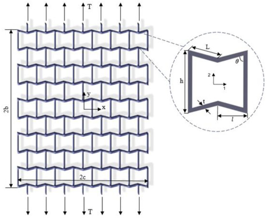
Figure 1.
Re-entrant lattice structure is made of hexgonal unit cells whose geometrical parameters are shown in the subfigure. The lattice structure is supposed to be under uniaxial tensile loading.
2.1. Elasticity Modeling
The 2D elasticity theory for a thin plate regardless of body force leads to the biharmonic equation (∇^4 φ = 0), where φ is an Airy stress function. Stress fields derived from an Airy stress function satisfy the equilibrium equation and correspond to compatible strain fields. Airy stress function is suitable to solve stress boundary condition problems. The only component of the stress boundary condition here is the in-plane tensile loading applied along the y-direction (Figure 1). Therefore, other stress components (i.e., ,) could be excluded, and the Airy stress function is obtained as follows:
The re-entrant structure is under stretch loading, as mentioned above and shown in Figure 1. The stress boundary conditions are written in Equation (2), where and are the normal stresses in the x and y direction, and is the in-plane shear stress.
The stress field can be calculated according to Airy functions as Equation (3).
The unknown coefficient () of the Airy function can be obtained from boundary conditions shown in Equation (2) as follows:
The stress–strain relationship according to Hooke’s law for orthotropic re-entrant structure under an in-plane state of stresses can be calculated as:
where are elastic constants that can be obtained from Equation (6).
where , , , , and are respectively the shear modulus, Young’s moduli, and Poisson’s ratios in principal directions (Figure 1). The mechanical properties, according to the unit cell geometrical parameters shown in Figure 1, can be written as follows [39]:
The strain relations (Equation (8)) can be calculated by replacing the Airy stress functions (Equation (3)) in Equation (5).
By integrating Equation (8), the displacement field in the x and y directions (i.e., and ) can be determined as:
The functions f and g are unknown functions that can be calculated by applying the shear strain relation given in Equation (8):
By integrating from Equation (10), the unknown functions can be written as:
where , , and are arbitrary constants of integration that indicate the translation and rotation of the plate. Since the structure is symmetrical, regardless of the rotation and rigid displacements, the displacement of the plate is expressed using Equations (12) and (13).
2.2. Finite Element Modeling
Finite element modeling (FEM) of the re-entrant structure has been performed by Abaqus 6.12.1, as shown in Figure 2. The 2D beam element (B31, linear element based on Timoshenko formulation) is used for computational simulation, which has a low analysis run time. We performed a mesh sensitivity analysis that showed the displacement results converged by element size equal to . Because of the symmetry of the plate, the midpoint of the plate was constrained in the x-direction. The upper and lower edges of the plate were in tension. The equivalent load in the y-direction must be equal to the corresponding load in the elasticity theory. Python programming language was used to parametrically model the structure in Abaqus.
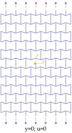
Figure 2.
Finite element model and boundary conditions.
3. Results and Design Producer
First, the effects of porosity on the elasticity solution were studied. The area of the lattice structure was directly calculated from Abaqus. We then calculated the void space by subtracting this area from the equivalent solid plate. The porosity was defined as the ratio of the void space filling to the equivalent solid plate. The porosity value can therefore change between 0 and 1, where 0 means the fully solid plate. Here, we changed the porosity of the lattice structures by changing the dimensions of their unit cells (i.e., and ) while the strut thickness (i.e., ) and unit cell angle (i.e., ) were kept unchanged (see Figure 3b–d).
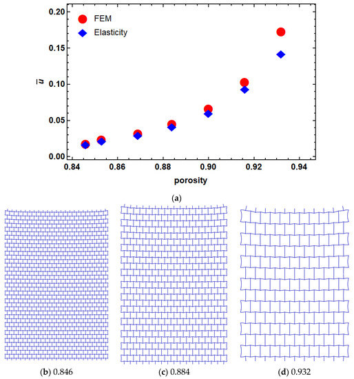
Figure 3.
Dimensionless displacement of re-entrant structure with different porosities (a) porosity. Examples of different porosity levels are shown subfigures (b) 0.846, (c) 0.884 and (d) 0.932.
The finite element model was compared with the results obtained from the elasticity approach with different porosities in Figure 3. The dimensionless results are represented as , where is the mean values of the elastic modulus of the lattice structure. As it can be seen in Figure 3, there is a good agreement between FEM and the results of the elasticity approach at a lower level of porosities. However, by increasing the porosity, the difference between the two models increased. This can be due to the rotation of unit cells in higher porosities that can lead to in-plane shear strain, thus violating our assumption regarding the zero-shear strain condition.
3.1. Variable Porosity Modeling
More complex re-entrant structures were modeled by changing their cell parameters in a way to have functionally graded unit cells in the y-direction and repeated unit cells in the x-direction. Since the unit cell angle has the greatest effect on the Poisson’s ratio [14], the presented model has an angle varying in the longitudinal direction. To satisfy the compatibility with other unit cell designs, the unit cell height also changed in each row according to a variable unit cell angle. The structure was divided into several rows with a specific angle in the longitudinal direction. As an example, a model with a linear variable angle was created as Equation (14).
The mechanical properties of the structure are obtained by replacing Equation (14) with Equation (7). Although the material properties vary along the y-direction, the presented elasticity solution remains valid because the stress function does not depend on y. Therefore, a variable deformation along the y-direction is the result of heterogeneity of mechanical properties in the y-direction. The dimensionless deformation () vs. normalized length () of a lattice structure with different levels of porosity are shown in Figure 4, where and . It can be seen in this figure that the difference between these two models (i.e., FEM and elasticity approach) increased by increasing the porosity. As mentioned above, this can be explained by creation of shear strain due to cell rotations in higher porosities. Based on this observation, we fixed the level of porosity to ~90% for our lattice designs hereafter.
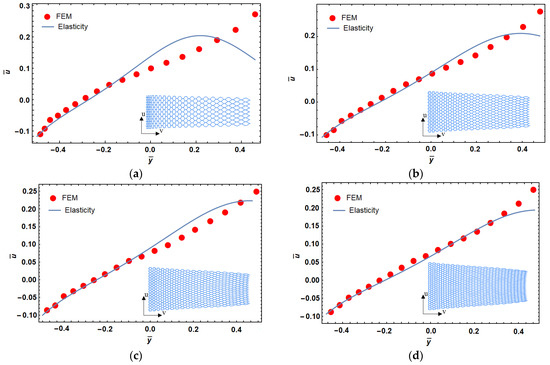
Figure 4.
Porosity effect on dimensionless displacement in functionally graded reentrant structure; 94% (a), 92% (b), 90% (c), and 88% (d) porosity.
Two other models with higher polynomial order for unit cell angle in a function of y-coordinate (rows) were considered in Figure 5 with the porosity of 88%. Equations (15) and (16) show the change of angle in the longitudinal direction for these models. These models consist of 23 × 35 cells and the dimension ratio with and . As it can be seen in Figure 5, the deformed structure has an arbitrary shape that can be used for reaching a specific design that will be discussed in the next section.
θ = 51.838 + 1.16y − 0.01202y2 + 0.0000644y3
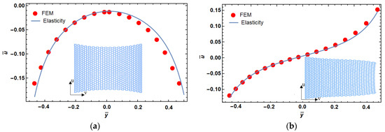
Figure 5.
Dimensionless displacement in functionally graded re-entrant structure for the desired parabola (a) and cubic (b) shapes.
3.2. Variable Porosity Designing
In this section, a method is presented to design a functionally graded re-entrant structure. Programming the microstructure to reach the desired deformation in tension is the main goal of this section. For this purpose, the angle of unit cells of the re-entrant structure must be calculated in terms of displacement.
The angle effect on the displacement field can be obtained from Equation (12). The angle of the unit cell affects the mechanical properties of the structure and can change the displacement field. Therefore, the displacement field was assumed to be a function of the angle of unit cells, as shown in Figure 6. We fitted a curve to calculate the angle of the unit cell as a function of displacement. Three different fitting curves were used (Table 1) that were calculated with MATLAB (R2014a, MathWorks, Natick, MA, USA). There is a minimum error for FC3 (Fit Curve 3) that consisted of polynomial and trigonometric functions (Table 1).
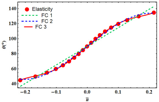
Figure 6.
Different fitting curves (FC) used to find the relationship between the unit cell angle vs. the dimensionless lateral displacements using the elasticity theory. The corresponding fitting equations are shown in Table 1.

Table 1.
Fitting curves (FC) and corresponding errors.
The desired deformation in tensile loading can be obtained by a re-entrant cellular structure using variation in angle. This change has the strongest effect on the mechanical properties of the lattice structure. The angle of each row can be obtained by fitting equations introduced in Table 1.
The angle of each row is dependent on the desired displacement. The desired displacement of each row must be calculated in the middle of the ligament of each row. The location of this point can be calculated from Equation (17), where m is the number of segments and n is the row number.
To show the capability of this method, a typical linear deformation is considered as Equation (18).
By dividing the height of the structure into 35 rows, the angle of each cell can be back-calculated from Table 1 and Equation (18). Figure 7 shows a comparison of the desired displacement with a designed model that was used in the development of FEM. First, the angle of each row is obtained, and then FEM is performed to see the deformation result. The design based on three different fitting curves, introduced in Table 1, was compared in this figure. It can be seen that FC3 is the best match with the target shape of deformation.
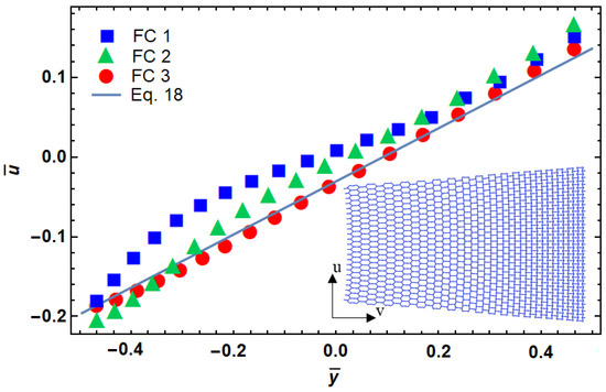
Figure 7.
Functionally graded design of a re-entrant cellular plate with non-dimensional lateral and longitudinal deformation.
The implemented method was compared with experimental test data published in [17]. The deformation field reported in this reference was used to design a functionally graded re-entrant structure with the presented method. The angle of cells was compared by reported angles in Figure 8. We observed a good match between the two approaches. A deviation between two results was observed at regions close to the gripping fixture. The difference in applied boundary conditions can be one of the sources of such difference between two approaches.
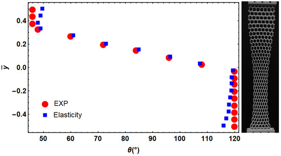
Figure 8.
Comparison between the designed angle of cells with the presented approach and those obtained from experimental results presented in [17] for the desired deformation.
To show the application of this method for the design of programmable shape-matching mechanical metamaterials, two arbitrary shapes were used in Figure 9. The first model is a vase structure with a special 1D curved contour line and the second model was the complex shape of a foot. We used our approach to design the corresponding microarchitectures of lattice structures so that under applied tensile loading, a particular 1D curved shape can be achieved. As a consequence, the presented design approach has a wide range of applications in the design of wearable medical (e.g., exo-skeletal prosthesis) and soft robotic devices (e.g., soft grippers to grip delicate objects). Re-entrant cell parameters can be designed with an elasticity approach, instead of other time-consuming methods, such FEM with 2D plane elements. Moreover, the proposed elasticity approach is sensitive to the level of porosity of the final structure as well as the applied boundary condition. Nevertheless, this approach may provide a fast and accurate design tool for the design of shape-matching mechanical metamaterials.
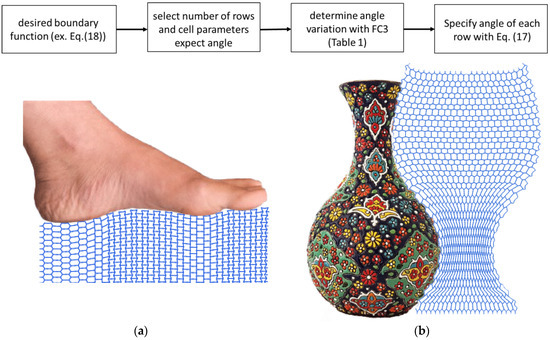
Figure 9.
A flowchart is shown in the top row showing the steps necessary for the design of mechanical metamaterials. This flowchart was used to back-calculate the microarchitecture of lattice structures for predicting the complex 1D shapes of two arbitrary examples, namely foot (a) and vase (b). Based on the elasticity approach proposed here, the microarchitectures of the lattice can be determined using re-entrant unit cells.
4. Conclusions
To conclude, here, the functionally graded mechanical metamaterials made from re-entrant structures under uniaxial tensile load were modeled using the elasticity theory and FEM. The effects of different morphological and geometrical parameters (i.e., porosity) on the overall shape of deformation of such materials were analyzed. We also showed how the presented approach can be used for the back-calculation of the microarchitectural designs of lattice structures in order to achieve any arbitrary target shape of deformation. This approach can be considered an effective tool in the design of programable mechanical metamaterials with shape matching properties. We expect this approach can be extended to the design of 3D structures with the same properties and predicting arbitrary shapes in 2D or 3D. The proposed design method can be used in many applications, such as soft robotics, fashion industries, and medical devices.
Author Contributions
Conceptualization, M.J.K. and M.J.M.; Investigation, A.B.; Methodology, M.J.K.; Project administration, M.J.K.; Software, A.B.; Supervision, M.J.K. and M.J.M.; Validation, S.S.; Writing—original draft, A.B.; Writing—review & editing, M.J.K. and M.J.M. All authors have read and agreed to the published version of the manuscript.
Institutional Review Board Statement
Not applicable.
Informed Consent Statement
Not applicable.
Data Availability Statement
The data presented in this study are available on reasonable request from the corresponding author.
Conflicts of Interest
The authors declare no conflict of interest.
References
- Mirzaali, M.J.; Mussi, V.; Vena, P.; Libonati, F.; Vergani, L.; Strano, M. Mimicking the loading adaptation of bone microstructure with aluminum foams. Mater. Des. 2017, 126, 207–218. [Google Scholar] [CrossRef] [Green Version]
- Bitzer, T.N. Honeycomb Technology: Materials, Design, Manufacturing, Applications and Testing; Springer Science & Business Media: Berlin, Germany, 1997. [Google Scholar]
- Ingrole, A.; Hao, A.; Liang, R. Design and modeling of auxetic and hybrid honeycomb structures for in-plane property enhancement. Mater. Des. 2017, 117, 72–83. [Google Scholar] [CrossRef]
- Rayneau-Kirkhope, D. Stiff auxetics: Hierarchy as a route to stiff, strong lattice based auxetic meta-materials. Sci. Rep. 2018, 8, 12437. [Google Scholar] [CrossRef] [PubMed] [Green Version]
- Khakalo, S.; Balobanov, V.; Niiranen, J. Modelling size-dependent bending, buckling and vibrations of 2D triangular lattices by strain gradient elasticity models: Applications to sandwich beams and auxetics. Int. J. Eng. Sci. 2018, 127, 33–52. [Google Scholar] [CrossRef] [Green Version]
- Nicolaou, Z.G.; Motter, A.E. Mechanical metamaterials with negative compressibility transitions. Nat. Mater. 2012, 11, 608–613. [Google Scholar] [CrossRef] [PubMed]
- Saxena, K.K.; Das, R.; Calius, E.P. Three decades of auxetics research− materials with negative Poisson’s ratio: A review. Adv. Eng. Mater. 2016, 18, 1847–1870. [Google Scholar] [CrossRef]
- Evans, K.E.; Alderson, A. Auxetic materials: Functional materials and structures from lateral thinking! Adv. Mater. 2000, 12, 617–628. [Google Scholar] [CrossRef]
- Hou, X.; Silberschmidt, V.V. Metamaterials with negative poisson’s ratio: A review of mechanical properties and deformation mechanisms. In Mechanics of Advanced Materials; Springer: Cham, Switzerland, 2015; pp. 155–179. [Google Scholar]
- Evans, K.E.; Alderson, K.L. Auxetic materials: The positive side of being negative. Eng. Sci. Educ. J. 2000, 9, 148–154. [Google Scholar] [CrossRef]
- Alderson, A.; Alderson, K.L. Auxetic materials. Proc. Inst. Mech. Eng. Part G J. Aerosp. Eng. 2007, 221, 565–575. [Google Scholar] [CrossRef]
- Lim, T.C. Auxetic Materials and Structures; Springer: Singapore, 2015. [Google Scholar]
- Kelkar, P.U.; Kim, H.S.; Cho, K.-H.; Kwak, J.Y.; Kang, C.-Y.; Song, H.-C. Cellular Auxetic Structures for Mechanical Metamaterials: A Review. Sensors 2020, 20, 3132. [Google Scholar] [CrossRef]
- Khoshgoftar, M.J.; Abbaszadeh, H. Experimental and finite element analysis of the effect of geometrical parameters on the mechanical behavior of auxetic cellular structure under static load. J. Strain Anal. Eng. Des. 2021, 56, 131–138. [Google Scholar] [CrossRef]
- Mirzaali, M.J.; Caracciolo, A.; Pahlavani, H.; Janbaz, S.; Vergani, L.; Zadpoor, A.A. Multi-material 3D printed mechanical metamaterials: Rational design of elastic properties through spatial distribution of hard and soft phases. Appl. Phys. Lett. 2018, 113, 241903. [Google Scholar] [CrossRef]
- Ou, J.; Ma, Z.; Peters, J.; Dai, S.; Vlavianos, N.; Ishii, H. KinetiX—Designing auxetic-inspired deformable material structures. Comput. Graph. 2018, 75, 72–81. [Google Scholar] [CrossRef]
- Mirzaali, M.J.; Janbaz, S.; Strano, M.; Vergani, L.; Zadpoor, A.A. Shape-matching soft mechanical metamaterials. Sci. Rep. 2018, 8, 965. [Google Scholar] [CrossRef]
- Liu, Y.; Hu, H. A review on auxetic structures and polymeric materials. Sci. Res. Essays 2010, 5, 1052–1063. [Google Scholar]
- Ren, X.; Das, R.; Tran, P.; Ngo, T.D.; Xie, Y.M. Auxetic metamaterials and structures: A review. Smart Mater. Struct. 2018, 27, 023001. [Google Scholar] [CrossRef]
- Laschi, C.; Cianchetti, M. Soft robotics: New perspectives for robot bodyware and control. Front. Bioeng. Biotechnol. 2014, 2, 3. [Google Scholar] [CrossRef] [PubMed] [Green Version]
- Mark, A.G.; Palagi, S.; Qiu, T.; Fischer, P. Auxetic metamaterial simplifies soft robot design. In Proceedings of the 2016 IEEE International Conference on Robotics and Automation (ICRA), Stockholm, Sweden, 16–21 May 2016; pp. 4951–4956. [Google Scholar]
- Awad, L.N.; Bae, J.; O’Donnell, K.; De Rossi, S.M.M.; Hendron, K.; Sloot, L.H.; Kudzia, P.; Allen, S.; Holt, K.G.; Ellis, T.D.; et al. A soft robotic exosuit improves walking in patients after stroke. Sci. Transl. Med. 2017, 9, eaai9084. [Google Scholar] [CrossRef] [PubMed] [Green Version]
- Coulais, C.; Teomy, E.; De Reus, K.; Shokef, Y.; Van Hecke, M. Combinatorial design of textured mechanical metamaterials. Nature 2016, 535, 529–532. [Google Scholar] [CrossRef] [Green Version]
- Konaković, M.; Crane, K.; Deng, B.; Bouaziz, S.; Piker, D.; Pauly, M. Beyond developable: Computational design and fabrication with auxetic materials. ACM Trans. Graph. TOG 2016, 35, 1–11. [Google Scholar] [CrossRef]
- Grima, J.N.; Gatt, R.; Farrugia, P.S. On the properties of auxetic meta-tetrachiral structures. Phys. Status Solidi B 2008, 245, 511–520. [Google Scholar] [CrossRef]
- Wang, X.-T.; Wang, B.; Li, X.-W.; Ma, L. Mechanical properties of 3D re-entrant auxetic cellular structures. Int. J. Mech. Sci. 2017, 131, 396–407. [Google Scholar] [CrossRef]
- Grima, J.N.; Caruana-Gauci, R.; Attard, D.; Gatt, R. Three-dimensional cellular structures with negative Poisson’s ratio and negative compressibility properties. Proc. R. Soc. A Math. Phys. Eng. Sci. 2012, 468, 3121–3138. [Google Scholar] [CrossRef] [Green Version]
- Grima, J.N.; Chetcuti, E.; Manicaro, E.; Attard, D.; Camilleri, M.; Gatt, R.; Evans, K.E. On the auxetic properties of generic rotating rigid triangles. Proc. R. Soc. A Math. Phys. Eng. Sci. 2012, 468, 810–830. [Google Scholar] [CrossRef]
- Ai, L.; Gao, X.L. An analytical model for star-shaped re-entrant lattice structures with the orthotropic symmetry and negative Poisson’s ratios. Int. J. Mech. Sci. 2018, 145, 158–170. [Google Scholar] [CrossRef]
- Zhang, J.; Lu, G.; Ruan, D.; Wang, Z. Tensile behavior of an auxetic structure: Analytical modeling and finite element analysis. Int. J. Mech. Sci. 2018, 136, 143–154. [Google Scholar] [CrossRef]
- Alomarah, A.; Ruan, D.; Masood, S. Tensile properties of an auxetic structure with re-entrant and chiral features—a finite element study. Int. J. Adv. Manuf. Technol. 2018, 99, 2425–2440. [Google Scholar] [CrossRef]
- Zhang, J.; Lu, G.; Wang, Z.; Ruan, D.; Alomarah, A.; Durandet, Y. Large deformation of an auxetic structure in tension: Experiments and finite element analysis. Compos. Struct. 2018, 184, 92–101. [Google Scholar] [CrossRef]
- Ai, L.; Gao, X.L. Three-dimensional metamaterials with a negative Poisson’s ratio and a non-positive coefficient of thermal expansion. Int. J. Mech. Sci. 2018, 135, 101–113. [Google Scholar] [CrossRef]
- Yang, H.; Ma, L. Multi-stable mechanical metamaterials with shape-reconfiguration and zero Poisson’s ratio. Mater. Des. 2018, 152, 181–190. [Google Scholar] [CrossRef]
- Dong, Z.; Li, Y.; Zhao, T.; Wu, W.; Xiao, D.; Liang, J. Experimental and numerical studies on the compressive mechanical properties of the metallic auxetic reentrant honeycomb. Mater. Des. 2019, 182, 108036. [Google Scholar] [CrossRef]
- Alomarah, A.; Ruan, D.; Masood, S.; Gao, Z. Compressive properties of a novel additively manufactured 3D auxetic structure. Smart Mater. Struct. 2019, 28, 085019. [Google Scholar] [CrossRef]
- Gibson, L.J.; Ashby, M.F.; Schajer, G.S.; Robertson, C.I. The mechanics of two-dimensional cellular materials. Proc. R. Soc. Lond. A Math. Phys. Sci. 1982, 382, 25–42. [Google Scholar] [CrossRef]
- Barber, J.R. Elasticity; Kluwer Academic Publishers: Dordrecht, The Netherlands, 2002; pp. 185–187. [Google Scholar]
- Zhu, X.; Zhang, J.; Zhang, W.; Chen, J. Vibration frequencies and energies of an auxetic honeycomb sandwich plate. Mech. Adv. Mater. Struct. 2019, 26, 1951–1957. [Google Scholar] [CrossRef]
Publisher’s Note: MDPI stays neutral with regard to jurisdictional claims in published maps and institutional affiliations. |
© 2021 by the authors. Licensee MDPI, Basel, Switzerland. This article is an open access article distributed under the terms and conditions of the Creative Commons Attribution (CC BY) license (https://creativecommons.org/licenses/by/4.0/).