
TiO2@Cu2O n-n Type Heterostructures for Photochemistry


Abstract
:
1. Introduction
2. Materials and Methods
2.1. Materials
2.2. Samples Preparation
2.3. Characterisation Techniques
3. Results
4. Discussion
5. Conclusions
Supplementary Materials
Author Contributions
Funding
Institutional Review Board Statement
Informed Consent Statement
Data Availability Statement
Conflicts of Interest
References
- Grätzel, M. Photoelectrochemical cells. Nature 2001, 414, 338–344. [Google Scholar] [CrossRef] [PubMed]
- Marschall, R. Semiconductor composites: Strategies for enhancing charge carrier separation to improve photocatalytic activity. Adv. Funct. Mater. 2014, 24, 2421–2440. [Google Scholar] [CrossRef]
- Li, J.; Wu, N. Semiconductor-based photocatalysts and photoelectrochemical cells for solar fuel generation: A review. Catal. Sci. Technol. 2015, 5, 1360–1384. [Google Scholar] [CrossRef]
- Thalluri, S.M.; Bai, L.; Lv, C.; Huang, Z.; Hu, X.; Liu, L. Strategies for Semiconductor/Electrocatalyst Coupling toward Solar-Driven Water Splitting. Adv. Sci. 2020, 7. [Google Scholar] [CrossRef] [Green Version]
- Nosaka, Y.; Nosaka, A.Y. Generation and Detection of Reactive Oxygen Species in Photocatalysis. Chem. Rev. 2017, 117, 11302–11336. [Google Scholar] [CrossRef]
- Garcia-Segura, S.; Brillas, E. Applied photoelectrocatalysis on the degradation of organic pollutants in wastewaters. J. Photochem. Photobiol. C Photochem. Rev. 2017, 31, 1–35. [Google Scholar] [CrossRef]
- Oturan, M.A.; Aaron, J.J. Advanced oxidation processes in water/wastewater treatment: Principles and applications. A review. Crit. Rev. Environ. Sci. Technol. 2014, 44, 2577–2641. [Google Scholar] [CrossRef]
- Daghrir, R.; Drogui, P.; Robert, D. Photoelectrocatalytic technologies for environmental applications. J. Photochem. Photobiol. A Chem. 2012, 238, 41–52. [Google Scholar] [CrossRef]
- Bessegato, G.G.; Guaraldo, T.T.; de Brito, J.F.; Brugnera, M.F.; Zanoni, M.V.B. Achievements and Trends in Photoelectrocatalysis: From Environmental to Energy Applications. Electrocatalysis 2015, 6, 415–441. [Google Scholar] [CrossRef] [Green Version]
- Radecka, M.; Kusior, A.; Trenczek-Zajac, A.; Zakrzewska, K. Oxide Nanomaterials for Photoelectrochemical Hydrogen Energy Sources. In Materials for Sustainable Energy; Academic Press: Cambridge, MA, USA, 2018; Volume 72, pp. 145–183. ISBN 9780128150771. [Google Scholar]
- Fujishima, A.; Honda, K. Electrochemical photolysis of water at a semiconductor electrode. Nature 1972, 238, 37–38. [Google Scholar] [CrossRef]
- Henderson, M.A. A surface science perspective on TiO2 photocatalysis. Surf. Sci. Rep. 2011, 66, 185–297. [Google Scholar] [CrossRef]
- Ahmad, H.; Kamarudin, S.K.; Minggu, L.J.; Kassim, M. Hydrogen from photo-catalytic water splitting process: A review. Renew. Sustain. Energy Rev. 2015, 43, 599–610. [Google Scholar] [CrossRef]
- Tee, S.Y.; Win, K.Y.; Teo, W.S.; Koh, L.D.; Liu, S.; Teng, C.P.; Han, M.Y. Recent Progress in Energy-Driven Water Splitting. Adv. Sci. 2017, 4, 1600337. [Google Scholar] [CrossRef] [Green Version]
- Zhang, L.; Jaroniec, M. Toward designing semiconductor-semiconductor heterojunctions for photocatalytic applications. Appl. Surf. Sci. 2018, 430, 2–17. [Google Scholar] [CrossRef]
- Roy, P.; Berger, S.; Schmuki, P. TiO2 nanotubes: Synthesis and applications. Angew. Chemie Int. Ed. 2011, 50, 2904–2939. [Google Scholar] [CrossRef]
- Wehrenfennig, C.; Palumbiny, C.M.; Snaith, H.J.; Johnston, M.B.; Schmidt-Mende, L.; Herz, L.M. Fast Charge-Carrier Trapping in TiO2 Nanotubes. J. Phys. Chem. C 2015, 119, 9159–9168. [Google Scholar] [CrossRef]
- Low, J.; Yu, J.; Jaroniec, M.; Wageh, S.; Al-Ghamdi, A.A. Heterojunction Photocatalysts. Adv. Mater. 2017, 29, 1–20. [Google Scholar] [CrossRef]
- Sun, B.; Shi, T.; Peng, Z.; Sheng, W.; Jiang, T.; Liao, G. Controlled fabrication of Sn/TiO2 nanorods for photoelectrochemical water splitting. Nanoscale Res. Lett. 2013, 8, 1–8. [Google Scholar] [CrossRef] [Green Version]
- Sun, Y.; Yan, K.P. Effect of anodization voltage on performance of TiO2 nanotube arrays for hydrogen generation in a two-compartment photoelectrochemical cell. Int. J. Hydrogen Energy 2014, 39, 11368–11375. [Google Scholar] [CrossRef]
- Radecka, M.; Rekas, M.; Trenczek-Zajac, A.; Zakrzewska, K. Importance of the band gap energy and flat band potential for application of modified TiO2 photoanodes in water photolysis. J. Power Sources 2008, 181, 46–55. [Google Scholar] [CrossRef]
- Menon, H.; Gopakumar, G.; Nair, V.S.; Nair, S.V.; Shanmugam, M. 2D-Layered MoS2-Incorporated TiO2-Nanofiber-Based Dye-Sensitized Solar Cells. ChemistrySelect 2018, 3, 5801–5807. [Google Scholar] [CrossRef]
- Cheng, C.; Ren, W.; Zhang, H. 3D TiO2/SnO2 hierarchically branched nanowires on transparent FTO substrate as photoanode for efficient water splitting. Nano Energy 2014, 5, 132–138. [Google Scholar] [CrossRef]
- Radecka, M.; Wnuk, A.; Trenczek-Zajac, A.; Schneider, K.; Zakrzewska, K. TiO2/SnO2 nanotubes for hydrogen generation by photoelectrochemical water splitting. Int. J. Hydrogen Energy 2015, 40, 841–851. [Google Scholar] [CrossRef]
- Yuan, W.; Yuan, J.; Xie, J.; Li, C.M. Polymer-Mediated Self-Assembly of TiO2@Cu2O Core-Shell Nanowire Array for Highly Efficient Photoelectrochemical Water Oxidation. ACS Appl. Mater. Interfaces 2016, 8, 6082–6092. [Google Scholar] [CrossRef]
- Yang, Y.; Xu, D.; Wu, Q.; Diao, P. Cu2O/CuO bilayered composite as a high-efficiency photocathode for photoelectrochemical hydrogen evolution reaction. Sci. Rep. 2016, 6, 35158. [Google Scholar] [CrossRef] [Green Version]
- Zhang, Q.; Zhang, K.; Xu, D.; Yang, G.; Huang, H.; Nie, F.; Liu, C.; Yang, S. CuO nanostructures: Synthesis, characterization, growth mechanisms, fundamental properties, and applications. Prog. Mater. Sci. 2014, 60, 208–337. [Google Scholar] [CrossRef]
- Koiki, B.A.; Arotiba, O.A. Cu2O as an emerging semiconductor in photocatalytic and photoelectrocatalytic treatment of water contaminated with organic substances: A review. RSC Adv. 2020, 10, 36514–36525. [Google Scholar] [CrossRef]
- Sun, S.; Zhang, X.; Yang, Q.; Liang, S.; Zhang, X.; Yang, Z. Cuprous oxide (Cu2O) crystals with tailored architectures: A comprehensive review on synthesis, fundamental properties, functional modifications and applications. Prog. Mater. Sci. 2018, 96, 111–173. [Google Scholar] [CrossRef] [Green Version]
- Kusior, A.; Michalec, K.; Jelen, P.; Radecka, M. Shaped Fe2O3 nanoparticles – Synthesis and enhanced photocatalytic degradation towards RhB. Appl. Surf. Sci. 2019, 476, 342–352. [Google Scholar] [CrossRef]
- Lin, Z.; Li, L.; Yu, L.; Li, W.; Yang, G. Dual-functional photocatalysis for hydrogen evolution from industrial wastewaters. Phys. Chem. Chem. Phys. 2017, 19, 8356–8362. [Google Scholar] [CrossRef]
- Trenczek-Zajac, A. Thermally oxidized CdS as a photoactive material. New J. Chem. 2019, 43, 8892–8902. [Google Scholar] [CrossRef]
- Shen, H.; Zhao, X.; Duan, L.; Liu, R.; Wu, H.; Hou, T.; Jiang, X.; Gao, H. Influence of interface combination of RGO-photosensitized SnO2@RGO core-shell structures on their photocatalytic performance. Appl. Surf. Sci. 2017, 391, 627–634. [Google Scholar] [CrossRef]
- Ohsaka, T.; Izumi, F.; Fujiki, Y. Raman spectrum of anatase, TiO2. J. Raman Spectrosc. 1978, 7, 321–324. [Google Scholar] [CrossRef]
- Xu, Y.H.; Liang, D.H.; Liu, M.L.; Liu, D. zhong Preparation and characterization of Cu2O-TiO2: Efficient photocatalytic degradation of methylene blue. Mater. Res. Bull. 2008, 43, 3474–3482. [Google Scholar] [CrossRef]
- Ma, Q.; Zhang, H.; Cui, Y.; Deng, X.; Guo, R.; Cheng, X.; Xie, M.; Cheng, Q. Fabrication of Cu2O/TiO2 nano-tube arrays photoelectrode and its enhanced photoelectrocatalytic performance for degradation of 2,4,6-trichlorophenol. J. Ind. Eng. Chem. 2018, 57, 181–187. [Google Scholar] [CrossRef]
- Liu, D.; Tian, R.; Wang, J.; Nie, E.; Piao, X.; Li, X.; Sun, Z. Photoelectrocatalytic degradation of methylene blue using F doped TiO2 photoelectrode under visible light irradiation. Chemosphere 2017, 185, 574–581. [Google Scholar] [CrossRef] [PubMed]
- da Silva, M.R.; Lucilha, A.C.; Afonso, R.; Dall’Antonia, L.H.; de Andrade Scalvi, L.V. Photoelectrochemical properties of FTO/m-BiVO4 electrode in different electrolytes solutions under visible light irradiation. Ionics 2014, 20, 105–113. [Google Scholar] [CrossRef]
- Xiong, L.; Huang, S.; Yang, X.; Qiu, M.; Chen, Z.; Yu, Y. P-Type and n-type Cu2O semiconductor thin films: Controllable preparation by simple solvothermal method and photoelectrochemical properties. Electrochim. Acta 2011, 56, 2735–2739. [Google Scholar] [CrossRef]
- Fernando, C.A.N.; De Silva, P.H.C.; Wethasinha, S.K.; Dharmadasa, I.M.; Delsol, T.; Simmonds, M.C. Investigation of n-type Cu2O layers prepared by a low cost chemical method for use in photo-voltaic thin film solar cells. Renew. Energy 2002, 26, 521–529. [Google Scholar] [CrossRef]
- McShane, C.M.; Choi, K.S. Photocurrent enhancement of n-type Cu2O electrodes achieved by controlling dendritic branching growth. J. Am. Chem. Soc. 2009, 131, 2561–2569. [Google Scholar] [CrossRef]
- Aguirre, E.M.; Zhou, R.; Eugene, A.J.; Guzman, M.I.; Grela, M.A. Cu2O/TiO2 heterostructures for CO2 reduction through a direct Z-scheme: Protecting Cu2O from photocorrosion. Appl. Catal. B Environ. 2017, 217, 485–493. [Google Scholar] [CrossRef]
- Siripala, W. Electrodeposition of n-type Cuprous Oxide Thin Films. ECS Trans. 2008, 11, 1–10. [Google Scholar] [CrossRef]
- Garuthara, R.; Siripala, W. Photoluminescence characterization of polycrystalline n-type Cu2O films. J. Lumin. 2006, 121, 173–178. [Google Scholar] [CrossRef]
- Gerischer, H. Solar Photoelectrolysis with Semiconductor Electrodes. In Solar Energy Conversion; Seraphin, B.O., Ed.; Springer: Berlin/Heidelberg, Germany, 1979; Volume 31, p. 338. ISBN 978-3-662-30849-3. [Google Scholar]
- Paracchino, A.; Laporte, V.; Sivula, K.; Grätzel, M.; Thimsen, E. Highly active oxide photocathode for photoelectrochemical water reduction. Nat. Mater. 2011, 10, 456–461. [Google Scholar] [CrossRef]


| System | Photoelectrode | Efficiency η (%) | Ref. | |
|---|---|---|---|---|
| at 0 (V) | at 0.5 (V) | |||
| TiO2 | TiO2 nanorods | 0.15 1 | – | [19] |
| TiO2 nanotubes | 0.25–1.6 | – | [20] | |
| TiO2 thin film | 1.65 | 1.90 | [21] | |
| TiO2@MoS2 | TiO2 nanofibers | 4.7 2 | [22] | |
| TiO2@MoS2 | 6.0 2 | |||
| TiO2@SnO2 | TiO2 nanowires | – | – | [23] |
| TiO2@SnO2 | 0.21 1 | – | ||
| TiO2 nanotubes | 0.34 | 0.39 | [24] | |
| TiO2@SnO2 | 0.39–1.61 | 0.47–2.12 | ||
| TiO2@Cu2O | TiO2 nanowires | – | 0.14 | [25] |
| TiO2@Cu2O | – | 0.39 | ||
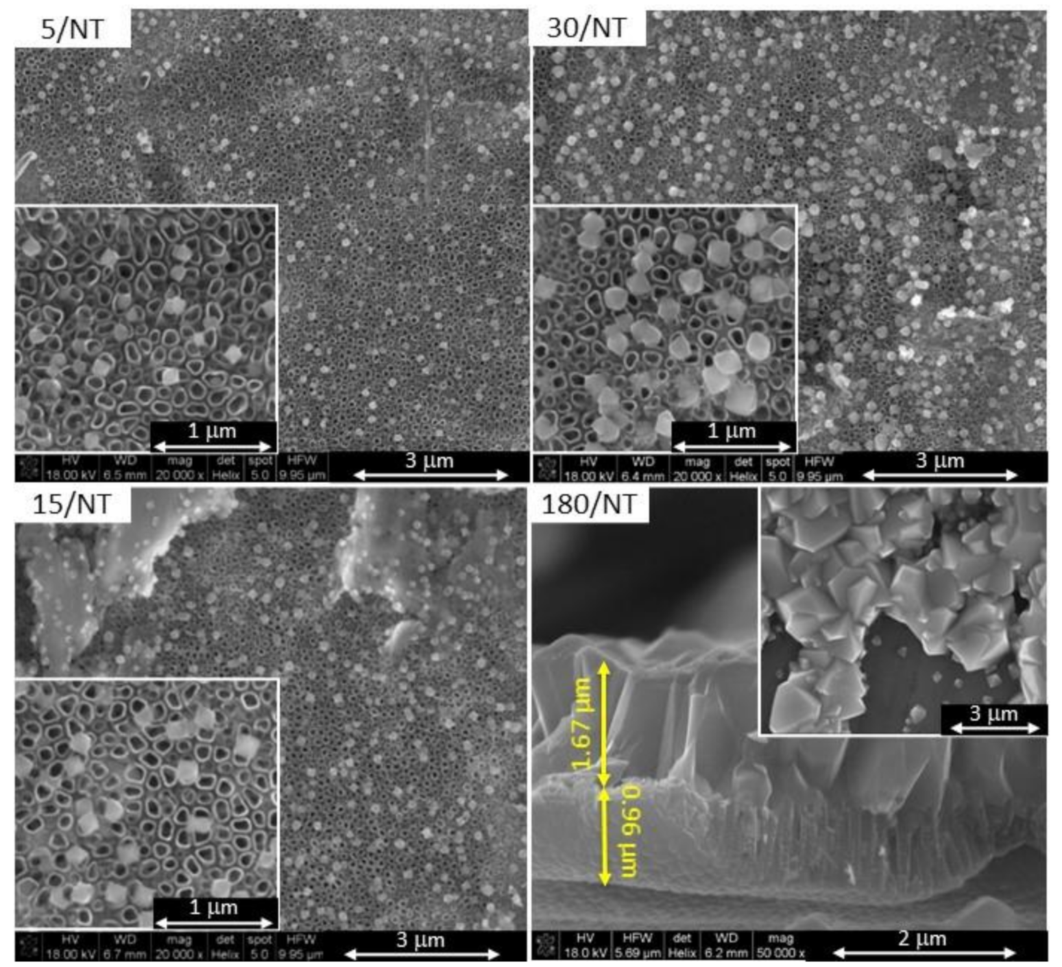
| Electrode Name | pH | Potential Difference (V) | Time (s) | Substrate |
|---|---|---|---|---|
| 5/NT | 12 | −0.36 | 5 | TiO2-NT |
| 15/NT | 15 | |||
| 30/NT | 30 | |||
| 180/NT | 180 |
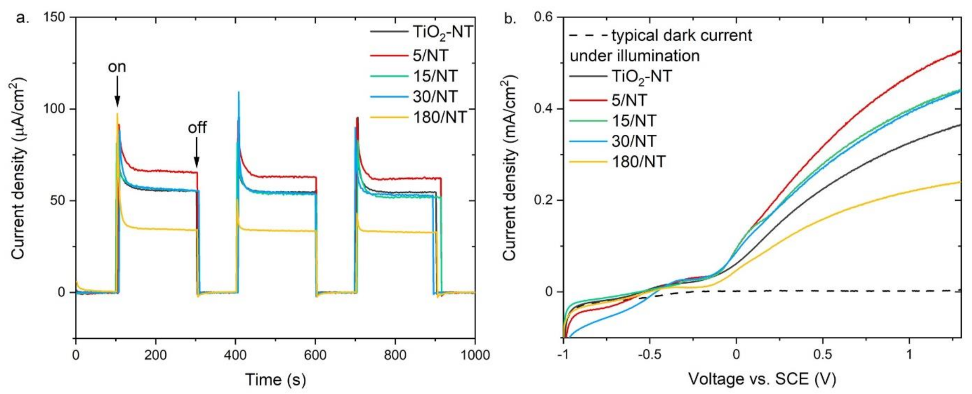
| Electrode Name | Iph (μA/cm2) | Ihetero/ITiO2-NT | Vfb (V) | |||
|---|---|---|---|---|---|---|
| at 0 (V) | at 1 (V) | at 0 (V) | at 1 (V) | Mott-Schottky | I-V 1 | |
| TiO2-NT | 61.9 | 324.9 | – | – | −0.50 | −0.55 |
| 5/NT | 94.9 | 470.7 | 1.53 | 1.45 | – | −0.52 |
| 15/NT | 94.5 | 398.9 | 1.53 | 1.23 | −0.56 | −0.56 |
| 30/NT | 86.8 | 392.4 | 1.40 | 1.21 | – | −0.46 |
| 180/NT | 50.0 | 218.9 | 0.81 | 0.67 | – | −0.50 |
Publisher’s Note: MDPI stays neutral with regard to jurisdictional claims in published maps and institutional affiliations. |
© 2021 by the authors. Licensee MDPI, Basel, Switzerland. This article is an open access article distributed under the terms and conditions of the Creative Commons Attribution (CC BY) license (https://creativecommons.org/licenses/by/4.0/).
Share and Cite
Trenczek-Zajac, A.; Banas-Gac, J.; Radecka, M. TiO2@Cu2O n-n Type Heterostructures for Photochemistry. Materials 2021, 14, 3725. https://doi.org/10.3390/ma14133725
Trenczek-Zajac A, Banas-Gac J, Radecka M. TiO2@Cu2O n-n Type Heterostructures for Photochemistry. Materials. 2021; 14(13):3725. https://doi.org/10.3390/ma14133725
Chicago/Turabian StyleTrenczek-Zajac, Anita, Joanna Banas-Gac, and Marta Radecka. 2021. "TiO2@Cu2O n-n Type Heterostructures for Photochemistry" Materials 14, no. 13: 3725. https://doi.org/10.3390/ma14133725
APA StyleTrenczek-Zajac, A., Banas-Gac, J., & Radecka, M. (2021). TiO2@Cu2O n-n Type Heterostructures for Photochemistry. Materials, 14(13), 3725. https://doi.org/10.3390/ma14133725