
Characterisation of Geogrid and Waste Tyres as Reinforcement Materials in Railway Track Beds


Abstract
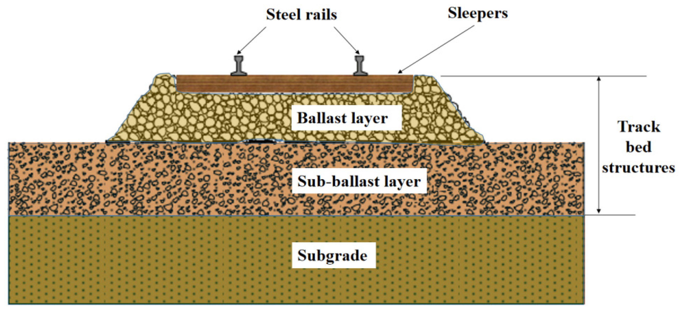
:1. Introduction
2. Test Equipment and Materials
2.1. Test Equipment
2.2. Test Filler
2.3. Reinforcement Materials
3. Test Procedure and Program
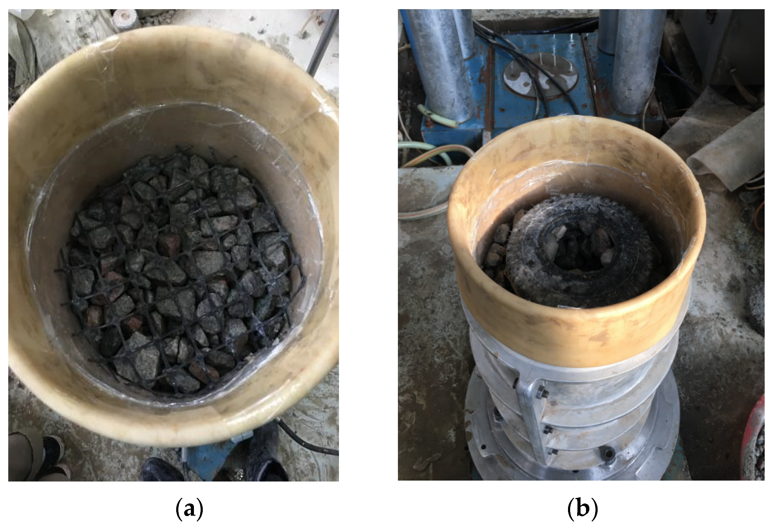
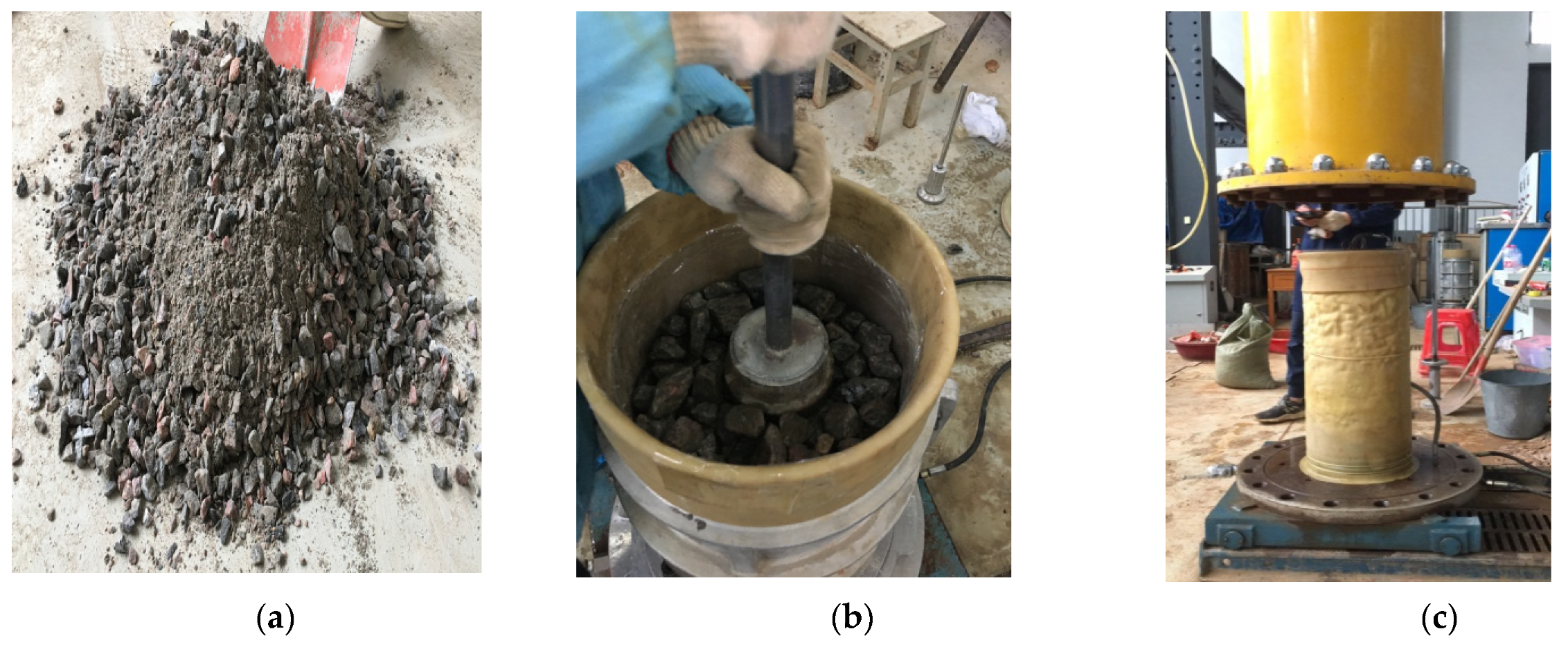
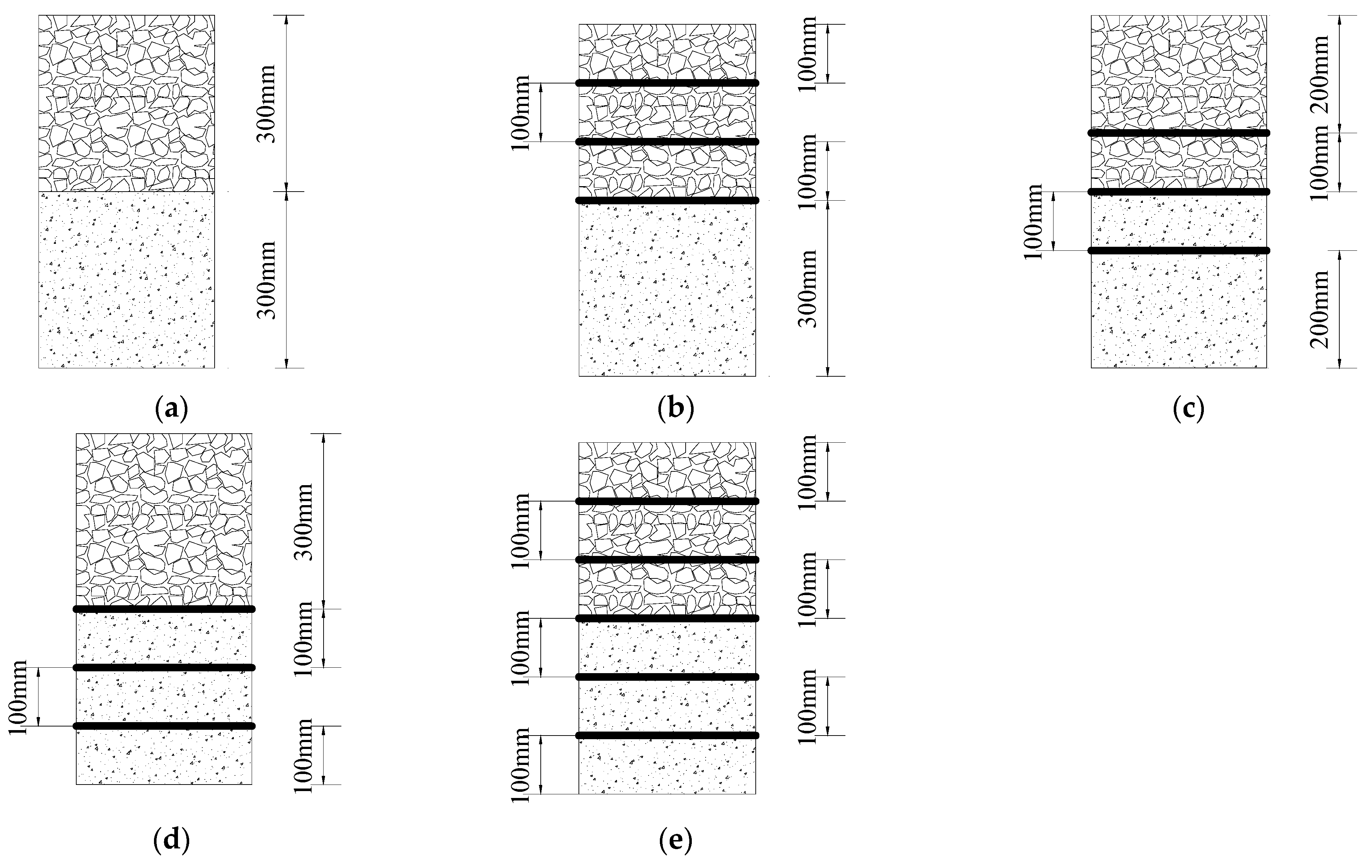
3.1. Sample Preparation
3.2. Test Program
4. Test Results and Analysis
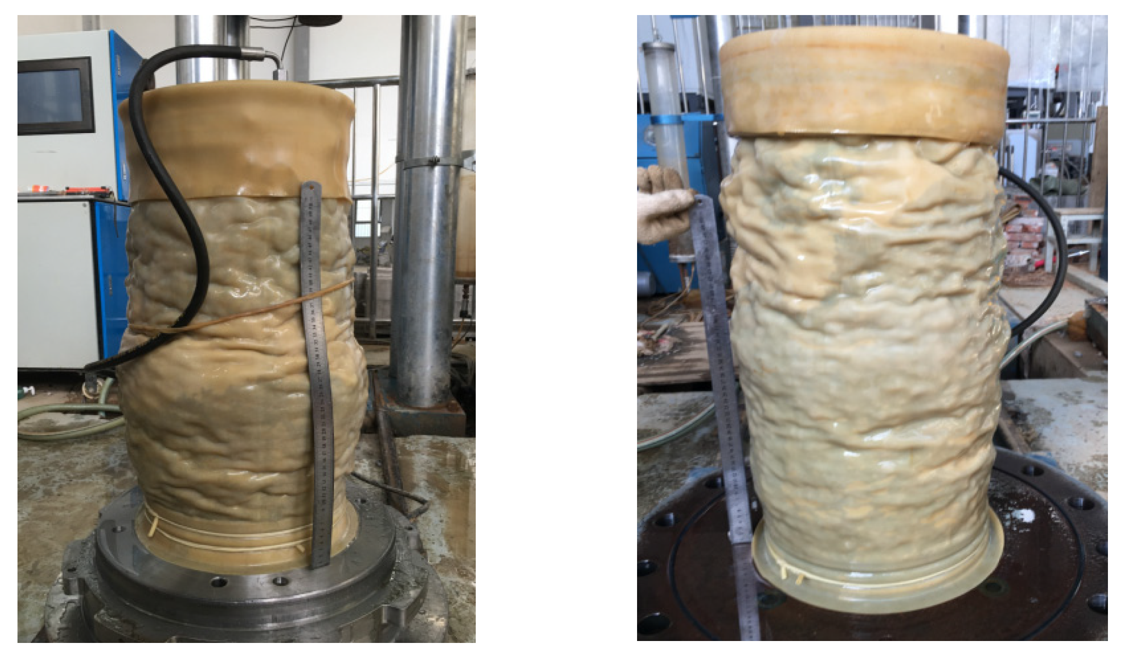
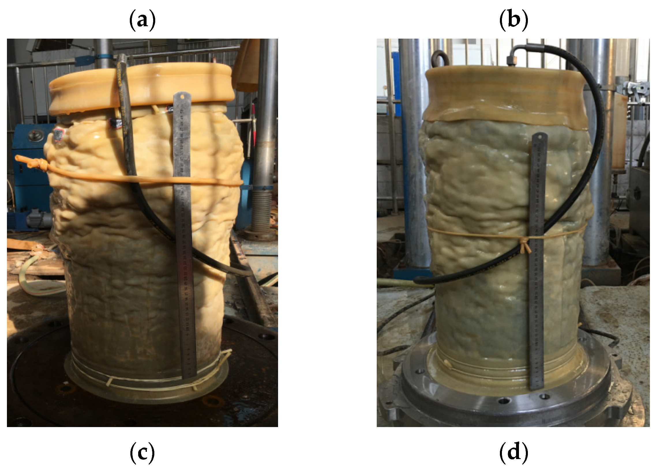
4.1. Shear Damage Characteristics of Samples at Different Reinforcement Positions
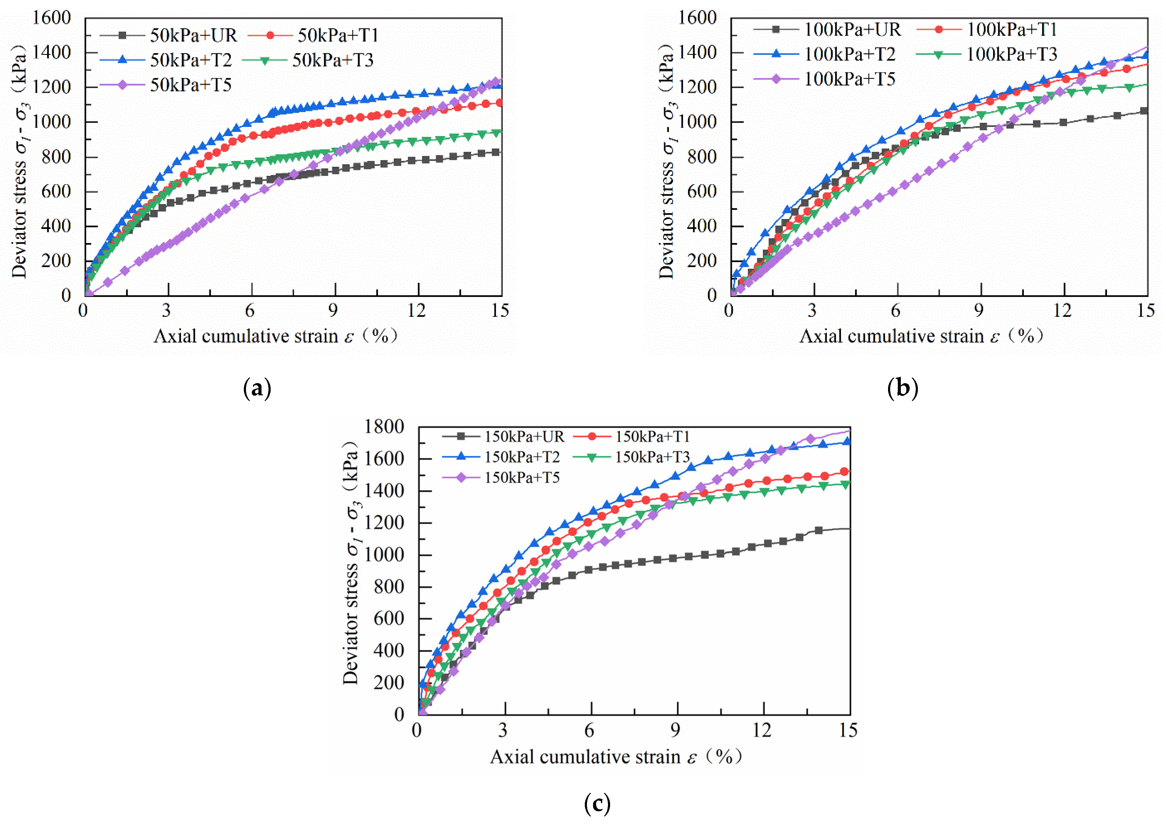
4.2. Stress–Strain Relationship Curve for Geogrid and Waste Tyre Reinforcement Track Bed Layer
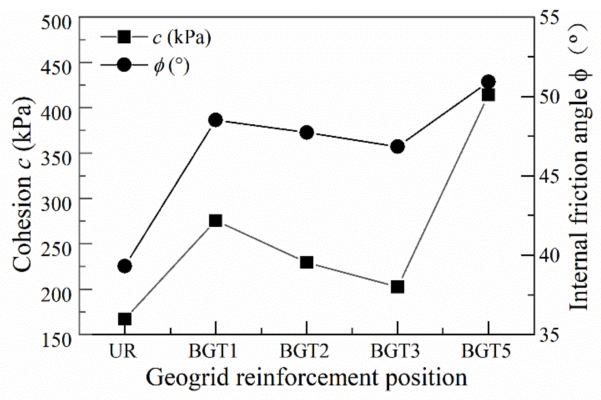
4.3. Shear Strength Parameters for Geogrid and Waste Tyre Reinforced Track Bed
4.4. Energy Absorption in Geogrid and Waste Tyre Reinforced Track Beds
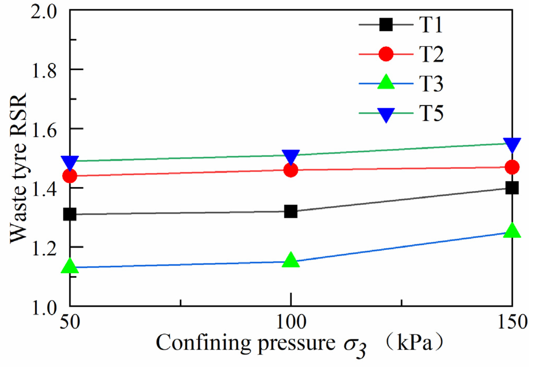
4.5. Reinforcement Strength Ratio under Different Confining Pressures
5. Conclusions
- (1)
- When the geogrid was reinforced at different locations in the track bed, the peak deviator stress in the track bed increased as the axial strain gradually increased. The whole change process was in a strain-hardening state. BGT1 has a higher peak deviator stress than the BGT2 and BGT3 reinforcement methods, and BGT1 has a better reinforcement effect than BGT2 and BGT3.
- (2)
- When waste tyres were reinforced in different positions of the roadbed, the effect of waste tyre reinforcement was not obvious at lower axial cumulative strains. As the axial cumulative strain increased, the roadbed remained strain-hardened for T1, T2, T3 and T5 reinforcement forms. T2 reinforcement forms were significantly better than T1 and T3.
- (3)
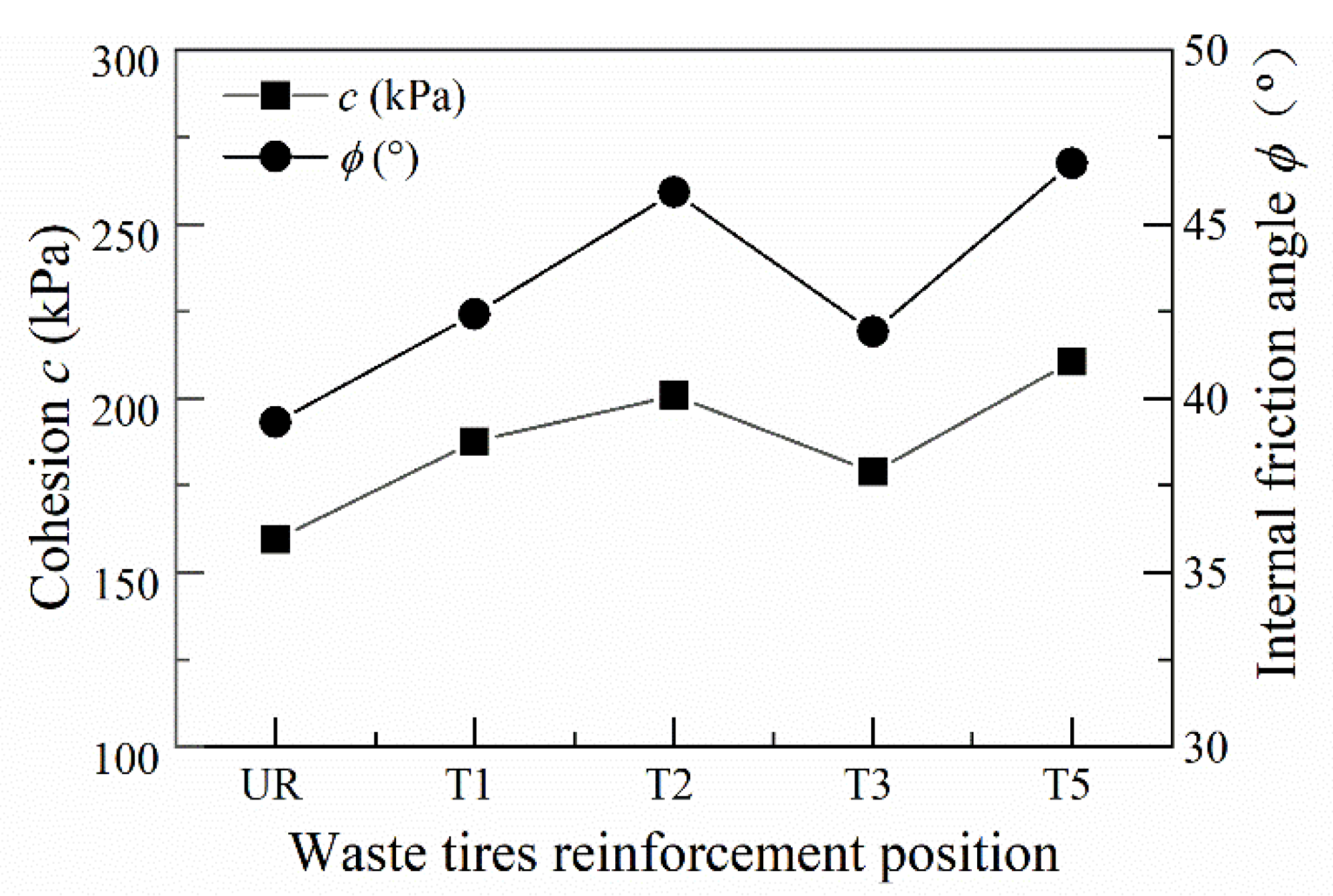
- The internal friction angle and cohesion of the geogrid and waste tyre reinforced track bed layers increased significantly. The shear strength of the BGT1 and T2 reinforced track bed layer was significantly better than the reinforcement at other locations. The best results in terms of shear strength were obtained when the reinforcement was in the form of BGT5 and T5.
- (4)
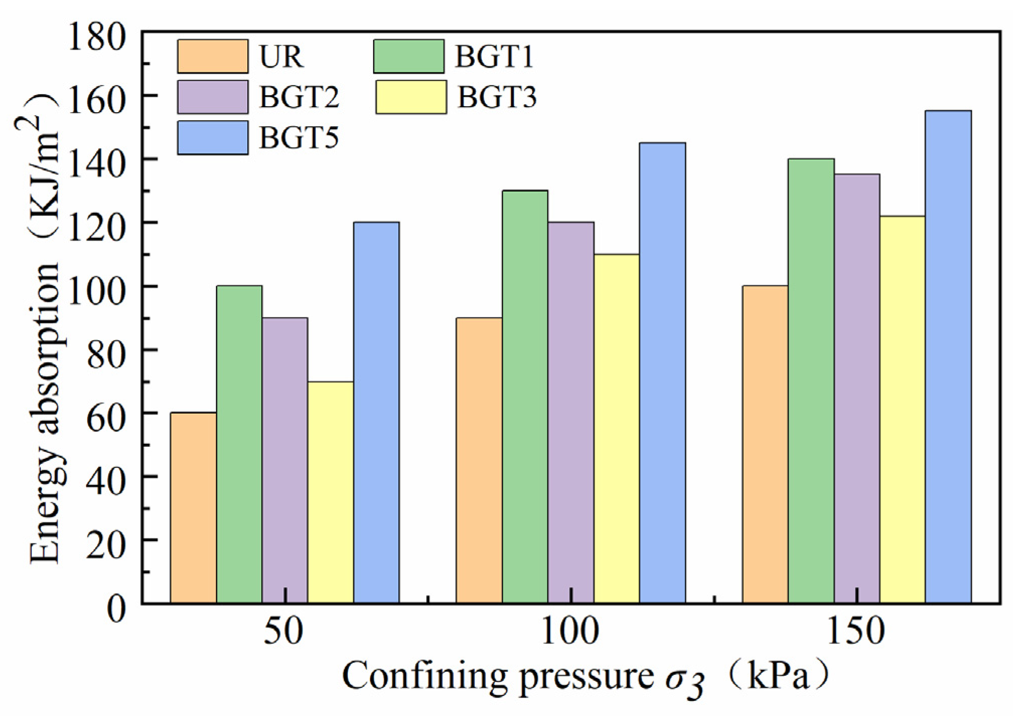
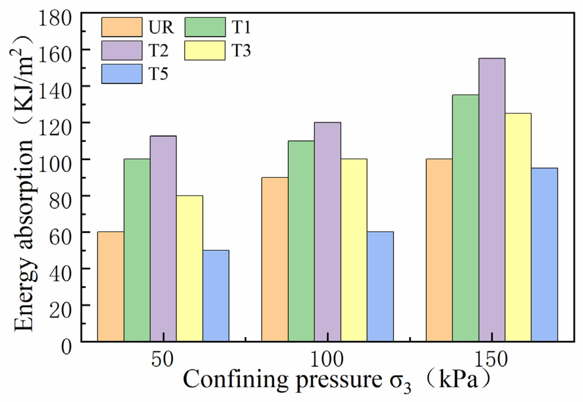
- The resistance to deformation of geogrid and waste tyre reinforced track beds is related to energy absorption. The more energy absorption of geogrid and waste tyre reinforced track beds, the greater their resistance to deformation. BGT1 requires the most energy absorption for deformation than BGT2 and BGT3. More energy is required for deformation of roadbeds under the bgt5 reinforcement method. The energy absorption required for the deformation of the waste tyre under stress was greatest when the waste tyre was reinforced by the T2 reinforcement method.
- (5)
- In the railway bed layer, geogrids and waste tyres have a significant reinforcing effect when placed, as reinforcing material, in the track bed layer.
Author Contributions
Funding
Conflicts of Interest
References
- Carneiro, V.H.; Puga, H.; Meireles, J. Vibration Damping and Acoustic Behavior of PU-Filled Non-Stochastic Aluminum Cellular Solids. Metals 2021, 11, 725–736. [Google Scholar] [CrossRef]
- Wang, J.Q.; Zhang, L.L.; Tang, Y.; Huang, S.B. Influence of reinforcement-arrangements on dynamic response of geogrid-reinforced foundation under repeated loadin. Constr. Build. Mater. 2021, 274, 122093. [Google Scholar] [CrossRef]
- Indraratna, B.; Sun, Q.; Grant, J. Behaviour of subballast reinforced with used tyre and potential application in rail tracks. Transp. Geotech. 2017, 12, 26–36. [Google Scholar] [CrossRef] [Green Version]
- Paixão, A.; Fortunato, E.; Calçada, R. A numerical study on the influence of backfill settlements in the train/track interaction at transition zones to railway bridges. Proc. Inst. Mech. Eng. Part F J. Rail Rapid Transit 2016, 230, 866–878. [Google Scholar] [CrossRef]
- D’Amato, M.; Laterza, M.; Casamassima, V.M. Seismic Performance Evaluation of Multi-Span Existing Masonry Arch Bridge. Open Civil Eng. J. 2017, M11 (Suppl. 5), 1191–1207. [Google Scholar] [CrossRef]
- Sweta, K.; Hussinia, K.K. Effect of geogrid on deformation response and resilient modulus of railroad ballast under cyclic loading. Constr. Build. Mater. 2020, 264, 120690. [Google Scholar] [CrossRef]
- Yu, Q.; Jie, H.; Pokharel, S.K. Performance of Triangular Aperture Geogrid-Reinforced Base Courses over Weak Subgrade under Cyclic Loading. J. Mater. Civil Eng. 2013, 25, 1013–1021. [Google Scholar]
- Hussaini, S.; Indraratna, B.; Vinod, J.S. On the shear behavior of ballast-geosynthetic interfaces. Geotech. Test. J. 2012, 35, 305–312. [Google Scholar]
- Indraratna, B.; Nimbalkar, S. Stress-Strain Degradation Response of Railway Ballast Stabilized with Geosynthetics. J. Geotech. Geoenviron. 2013, 139, 684–700. [Google Scholar] [CrossRef] [Green Version]
- Sol-Sánchez, M.; Moreno-Navarro, F.; Tauste-Martínez, R. Recycling Tire-Derived Aggregate as elastic particles under railway sleepers: Impact on track lateral resistance and durability. J. Clean. Prod. 2020, 277, 123322. [Google Scholar] [CrossRef]
- Indraratna, B.; Ngo, N.T.; Rujikiatkamjorn, C. Improved Performance of Ballasted Rail Tracks Using Plastics and Rubber Inclusions. Procedia Eng. 2017, 189, 207–214. [Google Scholar] [CrossRef]
- Esen, A.F.; Connolly, D.P.; Laghrouche, O.; Woodward, P.K.; Cebasek, T.M. Full-scale laboratory testing of a geosynthetically reinforced soil railway structure. Transpor. Geotech. 2021, 28, 100526. [Google Scholar] [CrossRef]
- Chawla, S.; Shahu, J.T.; Kumar, S. Analysis of cyclic deformation and post-cyclic strength of reinforced railway tracks on soft subgrade. Transpor. Geotech. 2021, 28, 100535. [Google Scholar] [CrossRef]
- Saberian, M.; Li, J.; Perera, S.; Zhou, A.; Roychand, R.; Ren, G. Large-scale direct shear testing of waste crushed rock reinforced with waste rubber as pavement base/subbase materials. Transpo. Geotech. 2021, 28, 100546. [Google Scholar] [CrossRef]
- Esmaeili, M.; Naderi, B.; Neyestanaki, H.K.; Khodaverdian, A. Investigating the effect of geogrid on stabilization of high railway embankments. Soils Found. 2018, 58, 319–332. [Google Scholar] [CrossRef]
- Hambirao, G.S.; Rakaraddi, D.P. Soil stabilization using waste shredded rubber tyre chips. J. Mech. Civil Eng. 2014, 11, 20–27. [Google Scholar] [CrossRef]
- Rahgozar, M.A.; Saberian, M. Geotechnical properties of peat soil stabilised with shredded waste tyre chips. Mires. Peat. 2016, 18, 1–12. [Google Scholar]
- Sadeghi, J.; Kian, A.R.T.; Ghiasinejad, H.; Moqaddam, M.F.; Motevalli, S. Effectiveness of geogrid reinforcement in improvement of mechanical behavior of sand-contaminated ballast. Geotext. Geomembr. 2020, 48, 768–779. [Google Scholar] [CrossRef]
- Hussaini, S.K.K.; Indraratna, B.; Vinod, J.S. A laboratory investigation to assess the functioning of railway ballast with and without geogrids. Transp. Geotech. 2016, 6, 45–54. [Google Scholar] [CrossRef] [Green Version]
- Brown, S.F.; Kwan, J.; Thom, N.H. Identifying the key parameters that influence geogrid reinforcement of railway ballast. Geotext. Geomembr. 2007, 25, 326–335. [Google Scholar] [CrossRef]
- Woodward, P.K.; Kennedy, J.; Laghrouche, O.; Connolly, D.P.; Medero, G. Study of railway track stiffness modification by polyurethane reinforcement of the ballast. Transp. Geotech. 2014, 1, 214–224. [Google Scholar] [CrossRef]
- Kennedy, J.; Woodward, P.K.; Medero, G.; Banimahd, M. Reducing railway track settlement using three-dimensional polyurethane polymer reinforcement of the ballast. Constr. Build. Mater. 2013, 44, 615–625. [Google Scholar] [CrossRef]
- Hongren, G.; Weimin, S.; Baoshan, H.; Xiang, S.; Bingye, H.; Hao, H.; Jinfeng, Z. Direct shear properties of railway ballast mixed with tire derived aggregates: Experimental and numerical investigations. Constr. Build. Mater. 2019, 200, 465–473. [Google Scholar] [CrossRef]
- Esmaeili, M.; Shamohammadi, A.; Farsi, S. Effect of deconstructed tire under sleeper pad onrailway ballast degradation under cyclic loading. Soil. Dyn. Earthq. Eng. 2020, 136, 106265. [Google Scholar] [CrossRef]
- Mohajerani, A.; Burnett, L.; Smith, J.V.; Markovski, S.; Rodwell, G.; Rahman, M.T.; Kurmus, H.; Mirzababaei, M.I.; Arulrajah, A.; Horpibulsuk, S.; et al. Recycling waste rubber tyres in construction materials and associated environmental considerations: A review. Resour. Conserv. Recy. 2020, 155, 104679. [Google Scholar] [CrossRef]
- Indraratna, B.; Sun, Q.; Heitor, A.; Grant, J. Performance of Rubber Tire-Confined Capping Layer under Cyclic Loading for Railroad Conditions. J. Mater. Civil Eng. 2018, 30, 06017021. [Google Scholar] [CrossRef]
- Li, L.; Qin, L.; Xiao, H. Large dynamic triaxial test study on reinforcement mechanisms of reinforced construction waste. Chin. J. Rock Mech. Eng. 2020, 39, 1682–1695. (In Chinese) [Google Scholar]
- Akbulut, S.; Arasan, S.; Kalkan, E. Modification of clayey soils using scrap tire rubber and synthetic fibers. App. Clay. Sci. 2007, 38, 23–32. [Google Scholar] [CrossRef]
- Rao, G.V.; Dutta, R.K. Compressibility and Strength Behaviour of Sand–tyre Chip Mixtures. Geotech. Geolo. Eng. 2006, 24, 711–724. [Google Scholar] [CrossRef]
- National Railway Administration of People’s Republic. TB 10625-2017 Code for Design of Heavy Haul Railway[S]; Railway Press: Beijing, China, 2017. (In Chinese)
- Ministry of Water Resources of the People’s Republic of China. SL 237-2019 Specification of Soil Test[S]; China Water & Power Press: Beijing, China, 2019. (In Chinese)
- Ministry of Railways of the People’s Republic of China. TB 10102-2010 Railway engineering geotechnical test procedures[S]; China Railway Press: Beijing, China, 2010. (In Chinese)
- Hamidi, A.; Hooresfand, M. Effect of fiber reinforcement on triaxial shear behavior of cement treated sand. Geotext. Geomembranes 2013, 36, 1–9. [Google Scholar] [CrossRef]


| Packing Classification | Max Dry Density/(g·cm−3) | Optimum Water Content/(%) | Cu | Cc |
|---|---|---|---|---|
| ballast | 2.18 | 0.79 | 6.32 | 1.16 |
| sub-ballast | 1.87 | 4.8 | 9.41 | 2.6 |
| Type | Ultimate Tensile Strength/(kN·mm−1) | Ultimate Elongation/% | Tensile Strength at Different Elongations in the Vertical/((kN·mm−1) | Tensile Strength at Different Elongations in the Horizontal/(kN·mm−1) | ||||
|---|---|---|---|---|---|---|---|---|
| MD | CMD | MD | CMD | 2% | 5% | 2% | 5% | |
| TGSG–3030 | 30 | 30 | ≤16 | ≤13 | ≥11 | ≥13 | ≥15 | ≥15 |
| Vertical Tensile Yield/(kN·m−1) | Vertical Yield Elongation/% | Single Tyre Size D × W × H/mm × mm × mm | Tensile Modulus at Different Strains/(kN·m−1) | |
|---|---|---|---|---|
| 2% | 5% | |||
| 54.6 | 75.8 | 170 × 50 × 50 | 33.2 | 78.1 |
| Samples No. | Confining Pressures σ3/kPa | Reinforced Materials | |
|---|---|---|---|
| Geogrid | Waste Tyres | ||
| 1 | 50 | UR | UR |
| 2 | BGT1 | T1 | |
| 3 | BGT2 | T2 | |
| 4 | BGT3 | T3 | |
| 5 | BGT5 | T5 | |
| 6 | 100 | UR | UR |
| 7 | BGT1 | T1 | |
| 8 | BGT2 | T2 | |
| 9 | BGT3 | T3 | |
| 10 | BGT5 | T5 | |
| 11 | 150 | UR | UR |
| 12 | BGT1 | T1 | |
| 13 | BGT2 | T2 | |
| 14 | BGT3 | T3 | |
| 15 | BGT5 | T5 | |
Publisher’s Note: MDPI stays neutral with regard to jurisdictional claims in published maps and institutional affiliations. |
© 2021 by the authors. Licensee MDPI, Basel, Switzerland. This article is an open access article distributed under the terms and conditions of the Creative Commons Attribution (CC BY) license (https://creativecommons.org/licenses/by/4.0/).
Share and Cite
Li, L.; Fang, Y.; Cheng, B.; Chen, N.; Tian, M.; Liu, Y. Characterisation of Geogrid and Waste Tyres as Reinforcement Materials in Railway Track Beds. Materials 2021, 14, 4162. https://doi.org/10.3390/ma14154162
Li L, Fang Y, Cheng B, Chen N, Tian M, Liu Y. Characterisation of Geogrid and Waste Tyres as Reinforcement Materials in Railway Track Beds. Materials. 2021; 14(15):4162. https://doi.org/10.3390/ma14154162
Chicago/Turabian StyleLi, Lihua, Yanan Fang, Bowen Cheng, Na Chen, Mi Tian, and Yiming Liu. 2021. "Characterisation of Geogrid and Waste Tyres as Reinforcement Materials in Railway Track Beds" Materials 14, no. 15: 4162. https://doi.org/10.3390/ma14154162