
Production of TiC-MMCs Reinforcements in Cast Ferrous Alloys Using In Situ Methods


Abstract
:1. Introduction
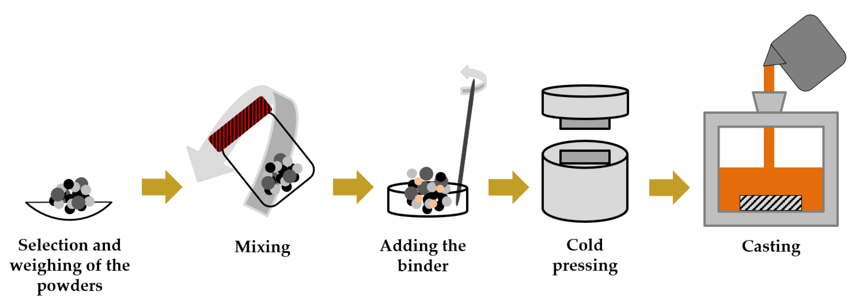
- Mixture and compaction of powders at room temperature or slightly higher;
- Start of combustion (ignition or auto-ignition);
- Self-propagating combustion, which leads to the formation of ceramics (carbides, borides, and silicides) or intermetallic compounds (e.g., TiAl).
2. Cast Ferrous Alloys Reinforced by SHS
3. Ti-C System
4. Ni-Ti-C and Ni-Ti-B4C Systems
5. Fe-Ti-C and Fe-Cr-Ti-C Systems
6. Cu-Ti-B4C/Cu-Ti-C Systems
7. Al-Ti-C and Al-Ti-B4C Systems
8. Conclusions
- The systems Ti-C, Ni-Ti-C, Ni-Ti-B4C, Fe-Ti-C/Fe-Cr-Ti-C, Cu-Ti-B4C, Al-Ti-C, and Al-Ti-B4C, have been the most used to produce metal matrix composites (MMCs) by casting route, with variable success. Most of the applications were developed in steel parts using the Fe-Ti-C/Fe-Cr-Ti-C powders systems and pressureless infiltration.
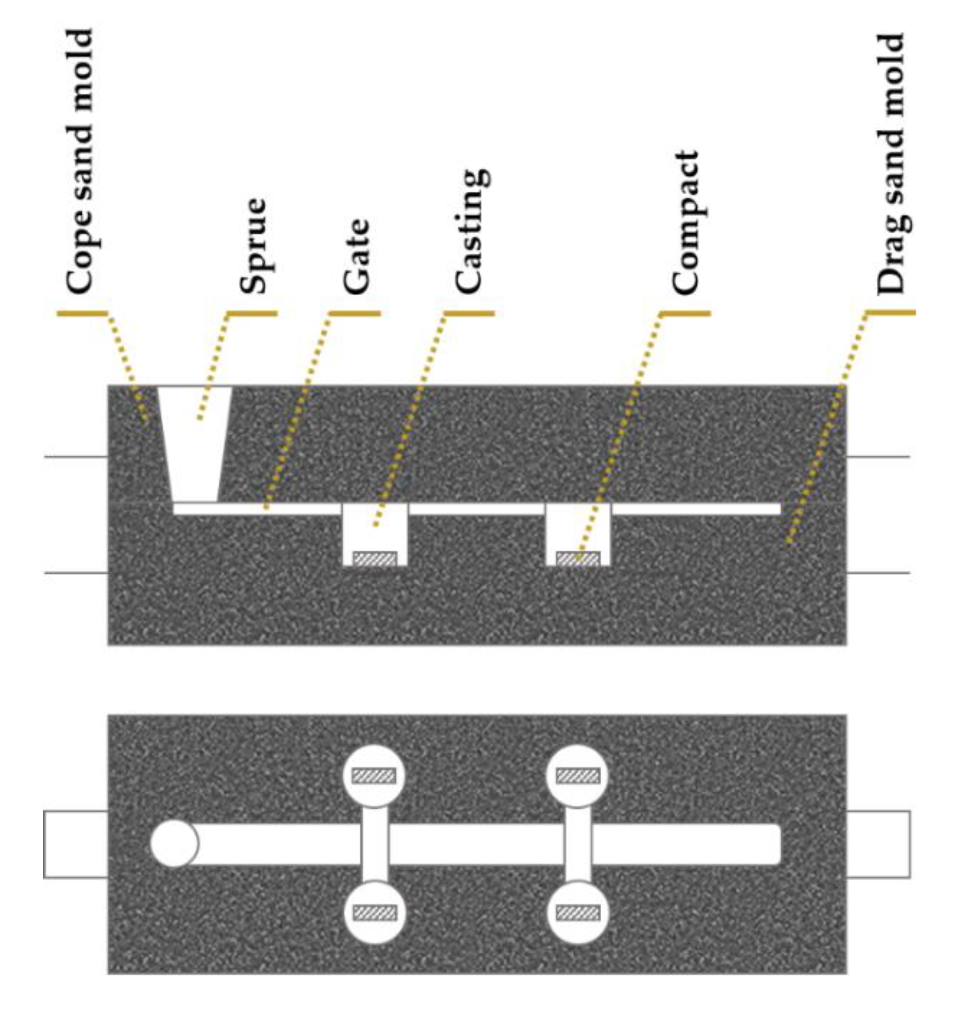
- In situ reinforcements are prepared following a common procedure that involves the mixture and compaction of metallic and non-metallic powders in a pre-form, which is inserted in the mold cavity before casting of the molten metal.
- In situ reinforcements are formed from self-propagating combustion reactions activated by the heat of the liquid metal that causes the synthesis of the ceramic phase.
- Variation of the process parameters such as compaction pressure, use of a binder, and initial powders ratio has been performed to improve the hardness and wear performance of the MMC produced.
- The development of TiC-MMCs using in situ methods allows the production of reinforcements up to five times harder than the base metal and three times more resistant to wear, thus achieving a high wear performance material.
- Despite the numerous studies that have been conducted till now, further research is needed to better understand the influence of the microstructural phases of TiC-MMCs on their mechanical properties and wear behavior.
Author Contributions
Funding
Institutional Review Board Statement
Informed Consent Statement
Conflicts of Interest
References
- Blau, P.J. ASM Handbook: Friction, Lubrication, and Wear Technology; ASM International: Materials Park, OH, USA, 1992; Volume 18. [Google Scholar]
- Davis, J.R. Surface Engineering for Corrosion and Wear Resistance; ASM international: Materials Park, OH, USA, 2001. [Google Scholar]
- Hutchings, I.; Shipway, P. Tribology: Friction and Wear of Engineering Materials, 2nd ed.; Butterworth-Heinemann: Oxford, UK, 2017. [Google Scholar]
- Straffelini, G. Friction and Wear: Methodologies for Design and Control; Springer: Cham, Switzerland, 2015. [Google Scholar] [CrossRef]
- Song, Y.; Wang, H. High speed sliding wear behavior of recycled WCP-reinforced ferrous matrix composites fabricated by centrifugal cast. Wear 2012, 276–277, 105–110. [Google Scholar] [CrossRef]
- Liang, Y.; Zhao, Q.; Han, Z.; Zhang, Z.; Li, X.; Ren, L. Dry Sliding Friction and Wear Mechanism of TiC-TiB2 Particulate Locally Reinforced Mn-Steel Matrix Composite from a Cu-Ti-B4C System via a Self-Propagating High-Temperature Synthesis (SHS) Casting Route. Tribol. Trans. 2015, 58, 567–575. [Google Scholar] [CrossRef]
- Olejnik, E.; Szymański, Ł.; Batóg, P.; Tokarski, T.; Kurtyka, P. TiC-FeCr local composite reinforcements obtained in situ in steel casting. J. Mater. Process. Technol. 2020, 275, 116157. [Google Scholar] [CrossRef]
- Li, Z.; Jiang, Y.; Zhou, R.; Chen, Z.; Shan, Q.; Tan, J. Effect of Cr addition on the microstructure and abrasive wear resistance of WC-reinforced iron matrix surface composites. J. Mater. Res. 2014, 29, 778–785. [Google Scholar] [CrossRef]
- Hu, S.; Zhao, Y.; Wang, Z.; Li, Y.; Jiang, Q. Fabrication of in situ TiC locally reinforced manganese steel matrix composite via combustion synthesis during casting. Mater. Des. 2013, 44, 340–345. [Google Scholar] [CrossRef]
- Olejnik, E.; Szymański, Ł.; Kurtyka, P.; Tokarski, T.; Grabowska, B.; Czapla, P. Hardness and Wear Resistance of TiC-Fe-Cr Locally Reinforcement Produced in Cast Steel. Arch. Foundry Eng. 2016, 16, 89–94. [Google Scholar] [CrossRef] [Green Version]
- Tang, S.; Gao, Y.; Li, Y. Recent developments in fabrication of ceramic particle reinforced iron matrix wear resistant surface composite using infiltration casting technology. Ironmak. Steelmak. 2014, 41, 633–640. [Google Scholar] [CrossRef]
- Kambakas, K.; Tsakiropoulos, P. Sedimentation casting of wear resistant metal matrix composites. Mater. Sci. Eng. A 2006, 435, 187–192. [Google Scholar] [CrossRef]
- Leibholz, R.; Robert, M.H.; Leibholz, H.; Bayraktar, E. Development of functionally graded nodular cast iron reinforced with recycled WC particles. In Mechanics of Composite and Multi-Functional Materials; Springer: Cham, Switzerland, 2017; Volume 7, pp. 241–249. [Google Scholar]
- Zhou, R.; Jiang, Y.; Lu, D. The effect of volume fraction of WC particles on erosion resistance of WC reinforced iron matrix surface composites. Wear 2003, 255, 134–138. [Google Scholar] [CrossRef]
- Zheng, K.; Gao, Y.; Tang, S.; Li, Y.; Ma, S.; Yi, D.; Zhang, Z. Interface Structure and Wear Behavior of Cr26 Ferrous Matrix Surface Composites Reinforced with CTCp. Tribol. Lett. 2014, 54, 15–23. [Google Scholar] [CrossRef]
- Zhang, P.; Zeng, S.; Zhang, Z.; Li, W. Microstructure and hardness of WC-Co particle reinforced iron matrix surface composite. China Foundry 2013, 10, 374–379. [Google Scholar]
- Kambakas, K.; Tsakiropoulos, P. Solidification of high-Cr white cast iron–WC particle reinforced composites. Mater. Sci. Eng. A 2005, 413, 538–544. [Google Scholar] [CrossRef]
- Li, Y.; Gao, Y. Three-body abrasive wear behavior of CC/high-Cr WCI composite and its interfacial characteristics. Wear 2010, 268, 511–518. [Google Scholar] [CrossRef]
- Merzhanov, A. Combustion processes that synthesize materials. J. Mater. Process. Technol. 1996, 56, 222–241. [Google Scholar] [CrossRef]
- Olejnik, E.; Tokarski, T.; Sikora, G.; Sobula, S.; Maziarz, W.; Szymański, Ł.; Grabowska, B. The Effect of Fe Addition on Fragmentation Phenomena, Macrostructure, Microstructure, and Hardness of TiC-Fe Local Reinforcements Fabricated In Situ in Steel Casting. Metall. Mater. Trans. A 2019, 50, 975–986. [Google Scholar] [CrossRef] [Green Version]
- Zhu, G.; Wang, W.; Wang, R.; Zhao, C.; Pan, W.; Huang, H.; Du, D.; Wang, D.; Shu, D.; Dong, A. Formation mechanism of spherical TiC in Ni-Ti-C system during combustion synthesis. Materials 2017, 10, 1007. [Google Scholar] [CrossRef] [PubMed] [Green Version]
- Bai, J.; Lin, T.; Wang, Z. Research on the TiC Reinforced Steel Matrix Surface Composites Prepared by SHS Casting. Appl. Mech. Mater. 2014, 713–715, 2848–2851. [Google Scholar] [CrossRef]
- Song, M.; Huang, B.; Zhang, M.; Li, J. Study of formation behavior of TiC ceramic obtained by self-propagating high-temperature synthesis from Al–Ti–C elemental powders. Int. J. Refract. Met. Hard Mater. 2009, 27, 584–589. [Google Scholar] [CrossRef]
- He, S.; Fan, X.A.; Chang, Q.; Xiao, L. TiC-Fe-Based Composite Coating Prepared by Self-Propagating High-Temperature Synthesis. Metall. Mater. Trans. B 2017, 48, 1748–1753. [Google Scholar] [CrossRef]
- Das, K.; Bandyopadhyay, T.; Das, S. A review on the various synthesis routes of TiC reinforced ferrous based composites. J. Mater. Sci. 2002, 37, 3881–3892. [Google Scholar] [CrossRef]
- Liang, Y.; Han, Z.; Zhang, Z.; Li, X.; Ren, L. Effect of Cu content in Cu–Ti–B4C system on fabricating TiC/TiB2 particulates locally reinforced steel matrix composites. Mater. Des. 2012, 40, 64–69. [Google Scholar] [CrossRef]
- Wang, Y.; Zhang, Z.; Wang, H.; Ma, B.; Jiang, Q. Effect of Fe content in Fe–Ti–B system on fabricating TiB2 particulate locally reinforced steel matrix composites. Mater. Sci. Eng. A 2006, 422, 339–345. [Google Scholar] [CrossRef]
- Riedel, R. Handbook of Ceramic Hard Materials; Wiley-VCH: Weinhim, Germany, 2000. [Google Scholar] [CrossRef]
- Rogachev, A.S.; Mukasyan, A.S. Combustion for Material Synthesis; CRC Press: Boca Raton, FL, USA, 2015. [Google Scholar] [CrossRef]
- Jiao, L.; Zhao, Y.T.; Wang, X.L.; Wu, Y.; Yang, S.N.; Li, K.N. The Research Progress of the In Situ Metal Matrix Composites. Key Eng. Mater. 2014, 575–576, 137–141. [Google Scholar] [CrossRef]
- Lebrat, J.; Varma, A.; Miller, A. Combustion synthesis of Ni3Al and Ni3Al-matrix composites. Metall. Trans. A 1992, 23, 69–76. [Google Scholar] [CrossRef]
- Munir, Z.A.; Anselmi-Tamburini, U. Self-propagating exothermic reactions: The synthesis of high-temperature materials by combustion. Mater. Sci. Rep. 1989, 3, 277–365. [Google Scholar] [CrossRef]
- Borovinskaya, I.P.; Gromov, A.A.; Levashov, E.A.; Maksimov, Y.M.; Mukasyan, A.S.; Rogachev, A.S. Concise Encyclopedia of Self-Propagating High-Temperature Synthesis: History, Theory, Technology, and Products; Elsevier: Amsterdam, The Netherlands, 2017. [Google Scholar]
- Pierson, H.O. Handbook of Refractory Carbides & Nitrides: Properties, Characteristics, Processing and Applications; Noyes Publications: Westwood, NJ, USA, 1996. [Google Scholar]
- Somiya, S. Handbook of Advanced Ceramics: Materials, Applications, Processing, and Properties, 2nd ed.; Academic Press: Waltham, MA, USA, 2013. [Google Scholar] [CrossRef]
- Xu, R.-R.; Su, Q. High Temperature Synthesis. In Modern Inorganic Synthetic Chemistry, 2nd ed.; Xu, R., Xu, Y., Eds.; Elsevier: Amsterdam, The Netherlands, 2017; pp. 9–43. [Google Scholar] [CrossRef]
- Jie-Cai, H.; Zhang, X.-H.; Wood, J. In-situ combustion synthesis and densification of TiC–xNi cermets. Mater. Sci. Eng. A 2000, 280, 328–333. [Google Scholar] [CrossRef]
- Yang, Y.; Wang, H.; Zhao, R.; Liang, Y.; Jiang, Q. Effect of Ni content on the reaction behaviors of self-propagating high-temperature synthesis in the Ni–Ti–B4C system. Int. J. Refract. Met. Hard Mater. 2008, 26, 77–83. [Google Scholar] [CrossRef]
- Yang, Y.; Wang, H.; Zhao, R.; Liang, Y.; Jiang, Q. Reaction mechanism of self-propagating high-temperature synthesis reaction in the Ni–Ti–B4C system. J. Mater. Res. 2008, 23, 2519–2527. [Google Scholar] [CrossRef]
- Zhang, M.; Hu, Q.; Huang, B.; Li, J.; Li, J. Study of formation behavior of TiC in the Fe–Ti–C system during combustion synthesis. Int. J. Refract. Met. Hard Mater. 2011, 29, 356–360. [Google Scholar] [CrossRef]
- Liang, Y.; Wang, H.; Yang, Y.; Zhao, R.; Jiang, Q. Effect of Cu content on the reaction behaviors of self-propagating high-temperature synthesis in Cu–Ti–B4C system. J. Alloys Compd. 2008, 462, 113–118. [Google Scholar] [CrossRef]
- Liang, Y.; Wang, H.; Yang, Y.; Du, Y.; Jiang, Q. Reaction path of the synthesis of TiC–TiB2 in Cu–Ti–B4C system. Int. J. Refract. Met. Hard Mater. 2008, 26, 383–388. [Google Scholar] [CrossRef]
- Choi, Y.; Rhee, S.-W. Effect of aluminium addition on the combustion reaction of titanium and carbon to form TiC. J. Mater. Sci. 1993, 28, 6669–6675. [Google Scholar] [CrossRef]
- Zou, B.; Shen, P.; Cao, X.; Jiang, Q. The mechanism of thermal explosion (TE) synthesis of TiC–TiB2 particulate locally reinforced steel matrix composites from an Al–Ti–B4C system via a TE-casting route. Mater. Chem. Phys. 2012, 132, 51–62. [Google Scholar] [CrossRef]
- Zou, B.; Shen, P.; Jiang, Q. Reaction synthesis of TiC–TiB2/Al composites from an Al–Ti–B4C system. J. Mater. Sci. 2007, 42, 9927–9933. [Google Scholar] [CrossRef]
- Zhao, Q.; Liang, Y.; Zhang, Z.; Li, X.; Ren, L. Effect of Al content on impact resistance behavior of Al-Ti-B4C composite fabricated under air atmosphere. Micron 2016, 91, 11–21. [Google Scholar] [CrossRef]
- Wang, H.Y.; Jiang, Q.C.; Ma, B.X.; Wang, Y.; Zhao, F. Fabrication of Steel Matrix Composite Locally Reinforced with in Situ TiB Particulate using Self–Propagating High–Temperature Synthesis Reaction of Ni–Ti–B System During Casting. Adv. Eng. Mater. 2005, 7, 58–63. [Google Scholar] [CrossRef]
- Bai, J.L.; Lin, T.; Wang, Z. Effect of Different Binder on the TiC Reinforced Steel Matrix Surface Composites. Adv. Mat. Res. 2015, 1089, 11–14. [Google Scholar] [CrossRef]
- Brown, I.; Owers, W. Fabrication, microstructure and properties of Fe–TiC ceramic–metal composites. Curr. Appl. Phys. 2004, 4, 171–174. [Google Scholar] [CrossRef]
- Olejnik, E.; Sobula, S.; Tokarski, T.; Sikora, G. Composite zones obtained by in situ synthesis in steel castings. Arch. Metall. Mater. 2013, 58, 769–773. [Google Scholar] [CrossRef] [Green Version]
- Fraś, E.; Olejnik, E.; Janas, A.; Kolbus, A. Fabrication of in situ composite layer on cast steel. Arch. Foundry Eng. 2010, 10, 175–180. [Google Scholar]
- Olejnik, E.; Sikora, G.; Sobula, S.; Tokarski, T.; Grabowska, B. Effect of compaction Pressure applied to TiC reactants on the Microstructure and Properties of Composite Zones Produced in situ in steel castings. Mater. Sci. Forum 2014, 782, 527–532. [Google Scholar] [CrossRef]
- Olejnik, E.; Janas, A.; Kolbus, A.; Sikora, G. The composition of reaction substrates for TiC carbides synthesis and its influence on the thickness of iron casting composite layer. Arch. Foundry Eng. 2011, 11, 165–168. [Google Scholar]
- Olejnik, E.; Górny, M.; Tokarski, T.; Grabowska, B.; Kmita, A.; Sikora, G. Composite zones produced in iron castings by in-situ synthesis of TiC carbides. Arch. Metall. Mater. 2013, 58, 465–471. [Google Scholar] [CrossRef] [Green Version]
- Fraś, E.; Olejnik, E.; Janas, A.; Kolbus, A. The morphology of TiC carbides produced in surface layers of carbon steel castings. Arch. Foundry Eng. 2010, 10, 39–42. [Google Scholar]
- Sobula, S.; Olejnik, E.; Tokarski, T. Wear Resistance of TiC Reinforced Cast Steel Matrix Composite. Arch. Foundry Eng. 2017, 17, 143–146. [Google Scholar] [CrossRef]
- Szymański, Ł.; Olejnik, E.; Tokarski, T.; Kurtyka, P.; Drożyński, D.; Żymankowska-Kumon, S. Reactive casting coatings for obtaining in situ composite layers based on Fe alloys. Surf. Coat. Technol. 2018, 350, 346–358. [Google Scholar] [CrossRef]
- Yang, Y.-F.; Wang, H.-Y.; Liang, Y.-H.; Zhao, R.-Y.; Jiang, Q.-C. Effect of C particle size on the porous formation of TiC particulate locally reinforced steel matrix composites via the SHS reaction of Ni–Ti–C system during casting. Mater. Sci. Eng. A 2008, 474, 355–362. [Google Scholar] [CrossRef]
- Jiang, Q.; Zhao, F.; Wang, H.; Zhang, Z. In situ TiC-reinforced steel composite fabricated via self-propagating high-temperature synthesis of Ni–Ti–C system. Mater. Lett. 2005, 59, 2043–2047. [Google Scholar] [CrossRef]
- Yang, Y.-F.; Wang, H.-Y.; Liang, Y.-H.; Zhao, R.-Y.; Jiang, Q.-C. Fabrication of steel matrix composites locally reinforced with different ratios of TiC/TiB2 particulates using SHS reactions of Ni–Ti–B4C and Ni–Ti–B4C–C systems during casting. Mater. Sci. Eng. A 2007, 445, 398–404. [Google Scholar] [CrossRef]
- Wang, H.; Huang, L.; Jiang, Q. In situ synthesis of TiB2–TiC particulates locally reinforced medium carbon steel–matrix composites via the SHS reaction of Ni–Ti–B4C system during casting. Mater. Sci. Eng. A 2005, 407, 98–104. [Google Scholar] [CrossRef]
- Olejnik, E.; Szymański, Ł.; Tokarski, T.; Opitek, B.; Kurtyka, P. Local composite reinforcements of TiC/FeMn type obtained in situ in steel castings. Arch. Civ. Mech. Eng. 2019, 19, 997–1005. [Google Scholar] [CrossRef]
- Liang, Y.; Zhao, Q.; Zhang, Z.; Han, Z.; Li, X.; Ren, L. In situ fabrication of TiC–TiB2 precipitates in Mn-steel using thermal explosion (TE) casting. J. Mater. Res. 2015, 30, 1019–1028. [Google Scholar] [CrossRef]
- Moreira, A.B.; Sousa, R.O.; Lacerda, P.; Ribeiro, L.M.M.; Pinto, A.M.P.; Vieira, M.F. Microstructural Characterization of TiC–White Cast-Iron Composites Fabricated by In Situ Technique. Materials 2020, 13, 209. [Google Scholar] [CrossRef] [Green Version]
- Jiang, Q.; Ma, B.; Wang, H.; Wang, Y.; Dong, Y. Fabrication of steel matrix composites locally reinforced with in situ TiB2–TiC particulates using self-propagating high-temperature synthesis reaction of Al–Ti–B4C system during casting. Compos. Part A Appl. Sci. Manuf. 2006, 37, 133–138. [Google Scholar] [CrossRef]
- Durlu, N. Titanium carbide based composites for high temperature applications. J. Eur. Ceram. Soc. 1999, 19, 2415–2419. [Google Scholar] [CrossRef]
- Jiang, Q.; Li, X.; Wang, H. Fabrication of TiC particulate reinforced magnesium matrix composites. Scr. Mater. 2003, 48, 713–717. [Google Scholar] [CrossRef]
- Wang, H.; Jiang, Q.; Zhao, Y.; Zhao, F.; Ma, B.-X.; Wang, Y. Fabrication of TiB2 and TiB2–TiC particulates reinforced magnesium matrix composites. Mater. Sci. Eng. A 2004, 372, 109–114. [Google Scholar] [CrossRef]
- Yang, Y.; Wang, H.; Zhao, R.; Jiang, Q. Effect of Reactant Particle Size on the Self-Propagating High-Temperature Synthesis Reaction Behaviors in the Ni-Ti-B4C System. Metall. Mater. Trans. A 2009, 40, 232–239. [Google Scholar] [CrossRef]
- Levashov, E.; Mukasyan, A.; Rogachev, A.; Shtansky, D. Self-propagating high-temperature synthesis of advanced materials and coatings. Int. Mater. Rev. 2017, 62, 203–239. [Google Scholar] [CrossRef]
- Fengjun, C.; Yisan, W. Microstructure of Fe–TiC surface composite produced by cast-sintering. Mater. Lett. 2007, 61, 1517–1521. [Google Scholar] [CrossRef]
- Li, Z.L.; Jiang, Y.H.; Huang, R.Q.; Zhou, R.; Yang, H.; Shan, Q. Microstructure and interface of TiC in situ synthesized reinforced steel-based surface composite prepared by V-EPC infiltrating method. In Proceedings of the Applied Mechanics, Materials and Manufacturing, Hong Kong, China, 17–18 August 2013; pp. 2680–2687. [Google Scholar] [CrossRef]
- Liang, Y.; Zhao, Q.; Zhang, Z.; Li, X.; Ren, L. Preparation and characterization of TiC particulate locally reinforced steel matrix composites from Cu–Ti–C system with various C particles. J. Asian Ceram. Soc. 2014, 2, 281–288. [Google Scholar] [CrossRef]
- Liang, Y.; Zhao, Q.; Han, Z.; Zhang, Z.; Li, X.; Ren, L. Microstructures and Wear Behavior of the TiC Ceramic Particulate Locally Reinforced Steel Matrix Composites from a Cu–Ti–C System. ISIJ Int. 2015, 55, 319–325. [Google Scholar] [CrossRef] [Green Version]
- Moreira, A.B.; Ribeiro, L.M.M.; Lacerda, P.; Vieira, M.F. Characterization of Iron-Matrix Composites Reinforced by In Situ TiC and Ex Situ WC Fabricated by Casting. Metals 2021, 11, 862. [Google Scholar] [CrossRef]

| Compound | Tad (°C) |
|---|---|
| TiC | 2940 |
| WC | 730 |
| SiC | 1530 |
| B4C | 730 |
| TiB2 | 2920 |
| Materials and Methods | Results | |||
|---|---|---|---|---|
| Base Metal | Reinforcing Materials | Method | Processing Conditions | |
| Steel [51] | Ti (99.8%; 44 µm) Graphite (99.99%; 44 µm) Alcohol At.r. Ti:graphite—1:1 Wt.r. powders to alcohol— 1:2 | Casting with Ar atmosphere | Mixing—24 h Drying—300 °C/10 min Pouring temperature—1550 °C | Reinforcement thickness: 550 µm–1200 µm |
| Hardness: 565–610 HV (matrix) 700–1134 HV (reinforcement) | ||||
| Cast iron [53] | Ti (99.98%, 44 µm) Graphite (99.99%, 30 µm) At.r. Ti:graphite: 1:1 m.wt.—0.01, 0.02, 0.03, 0.04 kg | Casting with Ar atmosphere (5 × 10⁻² MPa) | Mixing—24 h Drying—412 °C/10 min | Reinforcement thickness: 1 mm (m.wt. 0.01 kg) 6 mm (m.wt. 0.02 kg) 10 mm (m.wt. 0.03 kg) 15 mm (m.wt. 0.04 kg) |
| Low-carbon steel [50] | Ti (99.98%; 44 µm) Graphite (99.99%; 44 µm) At.r. Ti:graphite 1:1 | Infiltration casting | Mixing—24 h CP—500 MPa Pouring temperature—1600 °C | Hardness: 175 ± 4 HV 30 (base alloy) 696 ± 201 HV 30 (reinforcement) |
| Low-carbon steel [52] | Ti (99.42%, 44 µm)— 80 wt.% Graphite (99.99%, 44 µm)— 20 wt.% | Infiltration casting | Mixing—24 h CP—250, 300, 500, 600 MPa Pouring temperature—1625 °C | Hardness: 326 ± 23 HV 30 (base alloy) 489 ± 116 HV 30 (CP 250 MPa) 1034 ± 88 HV 30 (CP 300 MPa) 1081 ± 234 HV 30 (CP 500 MPa) 1523 ± 290 HV 30 (CP 600 MPa) |
| Low-carbon steel [56] | Ti (99.98%, 44 µm) Graphite (99.99%, 44 µm) At.r. Ti:graphite—1:1 | Infiltration casting | Mixing in a horizontal axle mixer—24 h CP—250, 600 MPa Pouring temperature—1600 °C | Wear mass loss: 0.32 g/16 h (CP 250 MPa) 0.13 g/16 h (CP 600 MPa) |
| Hardness: 489 ± 116 HV (CP 250 MPa) 1523 ± 290 HV (CP 600 MPa) | ||||
| Steel [57] | Ti (99.95%, 44 µm) Graphite (96%, 3 µm) At.% Ti:graphite—55:45 2, 5, 10% aqueous solutions of CMC Wt.r. powders to binder— 2:1 | Infiltration casting | Pouring temperature 1550 °C | Wear volume index: 315 mm3N−1m−1 (steel) 50 mm3N−1m−1 (2% CMC) 62 mm3N−1m−1 (5% CMC) |
| Hardness: 400 HV 1 (steel) 800 HV 1 (2% CMC) 625 HV 1 (5% CMC) | ||||
| Materials and Methods | Results | |||
|---|---|---|---|---|
| Base Metal | Reinforcing Materials | Method | Processing Conditions | |
| Medium- carbon steel [61] | Ni (99.8%; ≈5 µm) 10, 20, 30, 40 wt.% Ti (99.5%; ≈15 µm) B4C (98.0%; 3.5 µm) Stoichiometric— 2TiB2-TiC | Infiltration casting | Mixing with Ar atmosphere in a stainless-steel jar—50 rpm/8 h CP—80–85 MPa (70 ± 5% theoretical density) Drying—300 °C/3 h Pouring temperature—1600 °C | Hardness: <20 HRC (matrix) 44 HRC (10 wt.% Ni) 43 HRC (20 wt.% Ni) 48 HRC (30 wt.% Ni) 47 HRC (40 wt.% Ni) |
| High-carbon steel [59] | Ni (99.8%; ≈5 µm) 10–30 wt.% Ti (99.5%; ≈15 µm) C (99.9%; ≈38 µm) At.r. Ti:C—1:1 | Infiltration casting | Mixing in a ball milling—6 h CP—80–85 MPa (70–80% theoretical density) Pouring temperature—1600 °C | Wear volume loss: 2.311 × 10⁻¹⁰ m3m−1 (steel) 0.514 × 10⁻¹⁰ m3m−1 (10 wt.% Ni) |
| Hardness: 34 HRC (steel) 57 HRC (10 wt.% Ni) | ||||
| Austenite Mn-steel [60] | Ni (99.5%; 45 µm)— 40 wt.% (6 g) Ti (99.5%; ≈25 µm) 6.48, 6.65, 6.82 g B4C (98.0%; ≈25 µm) 2.52, 1.93, 1.33 g Graphite (99.5%; ≈38 µm) 0, 0.42, 0.85 g | Infiltration casting | Mixing in a ball milling—8 h Drying—300 °C/3 h Pouring temperature—1500 °C | Wear volume loss: 2.281 × 10⁻¹⁰ m3m−1 (steel) 0.5463 × 10⁻¹⁰ m3m−1 (specimen 1—6.48 g Ti; 2.52 g B4C) 0.7713 × 10⁻¹⁰ m3m−1 (specimen 2—6.65 g Ti; 1.93 g B4C; 0.42 C) 1.1406 × 10⁻¹⁰ m3m−1 (specimen 3—6.82 g Ti; 1.33 g B4C; 0.85 C) |
| Hardness: 20 HRC (steel) 46 HRC (specimen 1) 43 HRC (specimen 2) 40 HRC (specimen 3) | ||||
| Mn-steel [58] | Ni (99.5%; 45 µm)— 20 wt.% Ti (99.5%; 25 µm)— 64 wt.% Graphite (99.5%; ≈150, ≈38 and ≈1 µm)— 14 wt.% | Infiltration casting | Mixing—8 h Green densities of 75 ± 2% (theoretical density) | Wear volume loss: 2.268 × 10⁻¹⁰ m3m−1 (steel) 1.8771 × 10⁻¹⁰ m3m−1 (C: ≈150 µm) 1.4014 × 10⁻¹⁰ m3m−1 (C: ≈38 µm) 0.7152 × 10⁻¹⁰ m3m−1 (C: ≈1 µm) |
| Hardness: <20 HRC (steel) 40 HRC (C: ≈38 µm) 45 HRC (C: ≈1 µm) | ||||
| Materials and Methods | Results | |||
|---|---|---|---|---|
| Base Metal | Reinforcing Materials | Method | Processing Conditions | |
| Ferritic- pearlitic ductile iron [54] | Ti (99.98%; 44 µm) Graphite (99.99%; 44 µm) At.r. Ti:graphite—1:1 Fe (99.4%; 44 µm) 0 (M100), 10 (M90), 50 (M50) wt.% | Infiltration casting | Drying—100 °C/1 h CP—500 MPa Pouring temperature— 1450 °C | Hardness: 742 ± 163 HV (M100) 562 ± 29 HV (M90) 256 ± 38 HV (M50) |
| High Mn-steel [22] | Ti (30–50 µm) C (30–50 µm) 10, 20, 30, 40, 50 wt.% At.r. Ti:C—4:1 Ti + C: 90, 80, 70, 60, 50 wt.% Fe (40–60 µm) 10, 20, 30, 40, 50 wt.% PVA glue (2%)—3 wt.% | Infiltration casting (lost model) | CP—200 MPa | Wear rate: 40% relative wear rate (Ti + C—80 wt.%) |
| Hardness: 48 HRC (Ti + C—80 wt.%) | ||||
| Mn-steel [48] | Ti (30–50 µm) C (30–50 µm) At.r. Ti:C—4:1 Ti + C: 50, 60, 70, 80, 90 wt.% Fe (40–60 µm) 10, 20, 30, 40, 50 wt.% TiC (1–10 µm) PVA glue (2%)—3 wt.% Sodium silicate Water | Infiltration casting (lost model) | Mixing in a planetary tank—1 h Density of the compacts 1.80, 2.51, 2.79, 3.05, 3.39, 3.58 g∙cm−3 Pouring temperature— 1560 °C | Relative wear rate: 22% (density—3.05 g∙cm−3— CP 200 MPa; 80 wt.% Ti + C) |
| Hardness: ≈13 HRC (base metal) 63 HRC (density—3.05 g∙cm−3—CP 200 MPa; 80 wt.% Ti + C) | ||||
| Gray cast iron [24] | Fe (99.9%; <75 µm)—45 wt.% Ti (99.5%; <75 µm)—51.76 wt.% C (99.5%; <30 µm)—3.24 wt.% PVAL solution (glue) Wt.r. powders:glue—3:1 | Pressure-driven infiltration (lost model) | Mixing in a ball mill with a wt.r. ball:powder—10:1— 6 h Drying—50 °C/24 h Vacuum degree—0.06 MPa Pouring temperature— 1450 °C; 1500 °C; 550 °C; 1600 °C | Hardness: 51 HRC (1450 °C) 68 HRC (1500 °C) 61 HRC (1550 °C) 55 HRC (1600 °C) |
| Low-carbon steel [20] | Ti (99.8 wt.%, 44 µm) Graphite (99.9 wt.%, 44 µm) At.r. Ti:graphite—1:1 Fe (99.8 wt.%, 44 µm) 0, 10, 30, 50, 70 wt.% | Infiltration casting | Mixing in a shaker mixer— 6 h CP—500 MPa Compacts fixed in the mold cavity using a ceramic glue Pouring temperature— 1497 °C | Hardness: 500 HV 30 (with no Fe powder) 350 HV 30 (10 wt.% Fe) 400 HV 30 (30 wt.% Fe) 380 HV 30 (50 wt.% Fe) 250 HV 30 (70 wt.% Fe) |
| Materials and Methods | Results | |||
|---|---|---|---|---|
| Base Metal | Reinforcing Materials | Method | Processing Conditions | |
| Medium- carbon steel [71] | Low-melting-point compounds Cr—25–28 wt.% Ni—15–30 wt.% C—4–5 wt.% Fe—balance Carbide-forming compounds Ti—27.9 wt.% Si—1.03 wt.% Al—2.12 wt.% Graphite—6.5 wt.% Fe—balance Ratio low-melting-point compounds to the carbide-forming compounds—1:1 | Infiltration casting | Mixing in a ball mill—24 h CP—500 MPa Drying—500 °C/2 h Pouring temperature— 1600 °C | … |
| Medium Mn-steel [9] | High ferrotitanium (25–53 µm) Low ferrotitanium (25–53 µm) At.r. Ti:C—1:1 Graphite (99.9 wt.%, 53 µm) | Infiltration casting | Mixing in a stainless-steel jar—50 rpm/24 h CP—80 MPa Drying—120 °C/5 h | Weight loss: 0.0304 g (quenched Mn13 steel) 0.0162 g (reinforced zone) |
| Hardness: 18 HRC (quenched Mn13 steel) 55 HRC (reinforced zone) | ||||
| Medium- carbon steel [72] | Ti (50–60 µm) C (150–160 µm) Steel powder (35–40 µm) 0 and 20 wt.% | Pressure- driven infiltration (lost model) | Density of 50% Painted 1 mm thickness Drying—50 °C Vacuum degree— 0.065–0.060 MPa | … |
| Medium- carbon steel [10] | Ti (99.98%; 45 µm) Graphite (98%; 10 µm) At.r. Ti:graphite—1:1 Ti + graphite: 30 wt.% White cast iron powder (3,6 C; 2,2 Si; 0,8 Mn; 5,5 Ni; 10 Cr; 0,5 Mo; Fe bal.)—70 wt.% | Infiltration casting | Mixing—6 h Pouring temperature—1550 °C | Wear rate: 2.8 × 10⁻⁶ mm3N−1m−1 (reinforcement) |
| Hardness: 500 HV 1 (base alloy) 1500 HV 1 (reinforcement) | ||||
| Medium- carbon steel [62] | Ti (>99.95%, 45 µm) Graphite (>96%, 5 µm) At.r. Ti:graphite—1:1 Hadfield steel powder (moderator)—70 and 90 wt.% | Infiltration casting | Mixing—6 h CP—550 MPa Pouring temperature—1625 °C | Wear rate: 803.90 × 10⁻⁶ mm3N−1m−1 (base metal) 15.30 × 10⁻⁶ mm3N−1m−1 (70 wt.% moderator) 48.81 × 10⁻⁶ mm3N−1m−1 (90 wt.% moderator) |
| Hardness: Increase in hardness ranging from 200 to 300 HV) 785 HV 30 (70 wt.% moderator) 580 HV 30 (90 wt.% moderator) | ||||
| Medium- carbon steel [7] | Ti (99.95%, 44 µm) Graphite (>96%, 3 µm) At.r. Ti:graphite—1:1 High-chromium cast iron powder (moderator) 30, 50, 70 and 90 wt.% | Infiltration casting | Drying—150 °C CP—500 MPa Pouring temperature—1550 °C | Reinforcement thickness: 26 mm (30 wt.% moderator) 24 mm (50 wt.% moderator) 21 mm (70 wt.% moderator) 20 mm (90 wt.% moderator) |
| Wear rate: 321.13 mm3N−1m−1 (steel) 22.99 mm3N−1m−1 (30 wt.% moderator) 4.26 mm3N−1m−1 (50 wt.% moderator) 4.39 mm3N−1m−1 (70 wt.% moderator) 2.7 mm3N−1m−1 (90 wt.% moderator) | ||||
| Hardness: ≈460 HV 1 (steel) ≈725 HV 1 (30 wt.% moderator) ≈775 HV 1 (50 wt.% moderator) 927 HV 1 (70 wt.% moderator) ≈825 HV 1 (90 wt.% moderator) | ||||
| Materials and Methods | Results | |||
|---|---|---|---|---|
| Base Metal | Reinforcing Materials | Method | Processing Conditions | |
| Medium- carbon steel [26] | Cu (99.0%; ≈45 µm) 10–60 wt.% Ti (99.5%; ≈38 µm) B4C (99.9%; ≈3.5 µm) Stoichiometric 2TiB2-TiC | Infiltration casting | Mixing by ball-milling— 35 rpm/8 h Drying—300 °C/3 h Pouring temperature—1500 °C | Wear volume loss: 3.42 × 10⁻¹⁰ m3∙m−1 (steel) 1.17 × 10⁻¹⁰ m3∙m−1 (10 wt.% Cu) 1.09 × 10⁻¹⁰ m3∙m−1 (20 wt.% Cu) 0.92 × 10⁻¹⁰ m3∙m−1 (30 wt.% Cu) 1.35 × 10⁻¹⁰ m3∙m−1 (40 wt.% Cu) 1.97 × 10⁻¹⁰ m3∙m−1 (50 wt.% Cu) 2.35 × 10⁻¹⁰ m3∙m−1 (60 wt.% Cu) |
| Hardness: <20 HRC (steel) 50 HRC (10 wt.% Cu) 48 HRC (20 wt.% Cu) 49 HRC (30 wt.% Cu) 46 HRC (40 wt.% Cu) 41 HRC (50 wt.% Cu) 38 HRC (60 wt.% Cu) | ||||
| Medium Mn-steel [73] | Cu (99.5%, ≈6 µm)—20 wt.% Ti (99.5%, ≈15 µm) C (99.9%, ≈1, 38, 75, 150 µm) At.r. Ti:C—1:1 | Infiltration casting | Mixing—6 h Green densities of 70 ± 2% (theoretical density) Drying—150 °C/3 h Pouring temperature—1500 °C | Wear volume loss: 2.28 × 10⁻¹⁰ m3∙m−1 (steel) 2.07 × 10⁻¹⁰ m3∙m−1 (≈150 µm C) 1.52 × 10⁻¹⁰ m3∙m−1 (≈38 µm C) 0.75 × 10⁻¹⁰ m3∙m−1 (≈1 µm C) |
| Hardness: <20 HRC (steel) 34 HRC (≈150 µm C) 42 HRC (≈38 µm C) 46 HRC (≈1 µm C) | ||||
| Mn-steel [6] | Cu (99.5%; ≈3 µm) 10, 30, 50 wt.% Ti (99.5%; ≈38 µm) B4C (99.9%; ≈3.5 µm) Mole ratio Ti:B4C—3:1 | Infiltration casting | Mixing in a stainless-steel container—≈35 rpm/8 h CP—60 MPa Drying—300 °C/3 h Pouring temperature—1500 °C | Hardness: 18 HRC (steel) 50 HRC (10 wt.% Cu) 58 HRC (30 wt.% Cu) 41 HRC (50 wt.% Cu) |
| Mn-steel [63] | Cu (99.5%, ≈3 µm)—40 wt.% Ti (99.5%, ≈38 µm) B4C (99.9%; ≈3.5, ≈45, 150 µm) Mole ratio Ti:B4C—3:1 | Infiltration casting | Mixing—35 rpm/8 h (65% theoretical density) Drying—300 °C/3 h Pouring temperature—1600 °C | Wear mass loss (80 N): ≈17.8 mg (Mn-steel) ≈4.3 mg (≈3.5 µm B4C) ≈5.2 mg (≈45 µm B4C) ≈8 mg (≈150 µm B4C) |
| Hardness: <20 HRC (Mn-steel) 46 HRC (≈3.5 µm B4C) 42 HRC (≈45 µm B4C) 34 HRC (≈150 µm B4C) | ||||
| Mn-steel [74] | Cu (99.5%, ≈6 µm) 10–50wt.% Ti (99.5%, ≈25 µm) C (99.9, ≈38 µm) At.r. Ti:C—1:1 | Infiltration casting | Mixing in a stainless-steel container—6 h Green densities of 65 ± 2% (theoretical density) Drying—300 °C/3 h Pouring temperature—1500 °C | Wear mass loss (110 N): ≈8.5 mg (steel) ≈5.5 mg (10 wt.% Cu) ≈4.8 mg (20 wt.% Cu) ≈4.9 mg (30 wt.% Cu) ≈5.25 mg (40 wt.% Cu) ≈6.75 mg (50 wt.% Cu) |
| Hardness: <20 HRC (steel) 47 HRC (10 wt.% Cu) 36 HRC (20 wt.% Cu) 31 HRC (30 wt.% Cu) 29 HRC (40 wt.% Cu) 27 HRC (50 wt.% Cu) | ||||
| Materials and Methods | Results | |||
|---|---|---|---|---|
| Base Metal | Reinforcing Materials | Method | Processing Conditions | |
| High-Cr alloy steel [65] | Ti (99.5%; <25 µm) B4C (98.0%; <3.5 µm) At.r. B:Ti—2:1 At.r. C:Ti—1:1 Al (98.4%; <27 µm) 10, 20, 30, 40 wt.% | Infiltration casting | CP—70–75 MPa (65 ± 2% of theoretical values) Pouring temperature—1600 °C | Wear volume loss: 2.071 × 10⁻¹⁰ m3m−1 (steel) 1.595 × 10⁻¹⁰ m3m−1 (30 wt.% Al) |
| Hardness: 50 HRC (steel) 57 HRC (30 wt.% Al) | ||||
| Medium- carbon steel [44] | Al (99%; ≈29 µm)—30 wt.% Ti (99.5%; ≈38–48 µm) B4C (97%; 2.5–3.5; 20–28; 28–40; 63–80, 100–125 µm) Mole ratio Ti:B4C—3:1 | Infiltration casting | Mixing in a stainless-steel container—≈35 rpm/8 h CP—≈60 MPa (green densities of 65 ± 2%) | … |
| High-Cr white cast iron [64] | Al (99.0%, 12 µm)—20 wt.% Ti (99.5%, 43 µm)—64 wt.% Graphite (99.0%, 43 µm)— 16 wt.% | Infiltration casting | Mixing in a shaker mixer—7 h CP—70 MPa Pouring temperature—1460 °C | Reinforcement thickness: 6 mm |
| High-Cr white cast iron [75] | Al (99.0%, 12 µm)—20 wt.% Ti (99.5%, 43 µm)—64 wt.% Graphite (99.0%, 43 µm)— 16 wt.% | Infiltration casting | Mixing in a shaker mixer—7 h CP—70 MPa Pouring temperature—1460 °C | Reinforcement thickness: 6 mm |
| Wear rate: 1.29 × 10⁻⁶ mm3∙N−1∙mm−1 (base metal) 9.01 × 10⁻⁷ mm3∙N−1∙mm−1 (reinforcement) | ||||
| Hardness: 579 ± 47 HV 30 (base metal) 797 ± 112 H V30 (reinforcement) | ||||
Publisher’s Note: MDPI stays neutral with regard to jurisdictional claims in published maps and institutional affiliations. |
© 2021 by the authors. Licensee MDPI, Basel, Switzerland. This article is an open access article distributed under the terms and conditions of the Creative Commons Attribution (CC BY) license (https://creativecommons.org/licenses/by/4.0/).
Share and Cite
Moreira, A.B.; Ribeiro, L.M.M.; Vieira, M.F. Production of TiC-MMCs Reinforcements in Cast Ferrous Alloys Using In Situ Methods. Materials 2021, 14, 5072. https://doi.org/10.3390/ma14175072
Moreira AB, Ribeiro LMM, Vieira MF. Production of TiC-MMCs Reinforcements in Cast Ferrous Alloys Using In Situ Methods. Materials. 2021; 14(17):5072. https://doi.org/10.3390/ma14175072
Chicago/Turabian StyleMoreira, Aida B., Laura M. M. Ribeiro, and Manuel F. Vieira. 2021. "Production of TiC-MMCs Reinforcements in Cast Ferrous Alloys Using In Situ Methods" Materials 14, no. 17: 5072. https://doi.org/10.3390/ma14175072