
Tunable, Anisotropic Permeability and Spatial Flow of SLM Manufactured Structures

Abstract
:
1. Introduction
2. Materials and Methods
2.1. Porosity and Permeability
2.2. Experimental Setup for Permeability Measurement
2.3. Selective Laser Melting
3. Results and Discussion
3.1. Single Walls
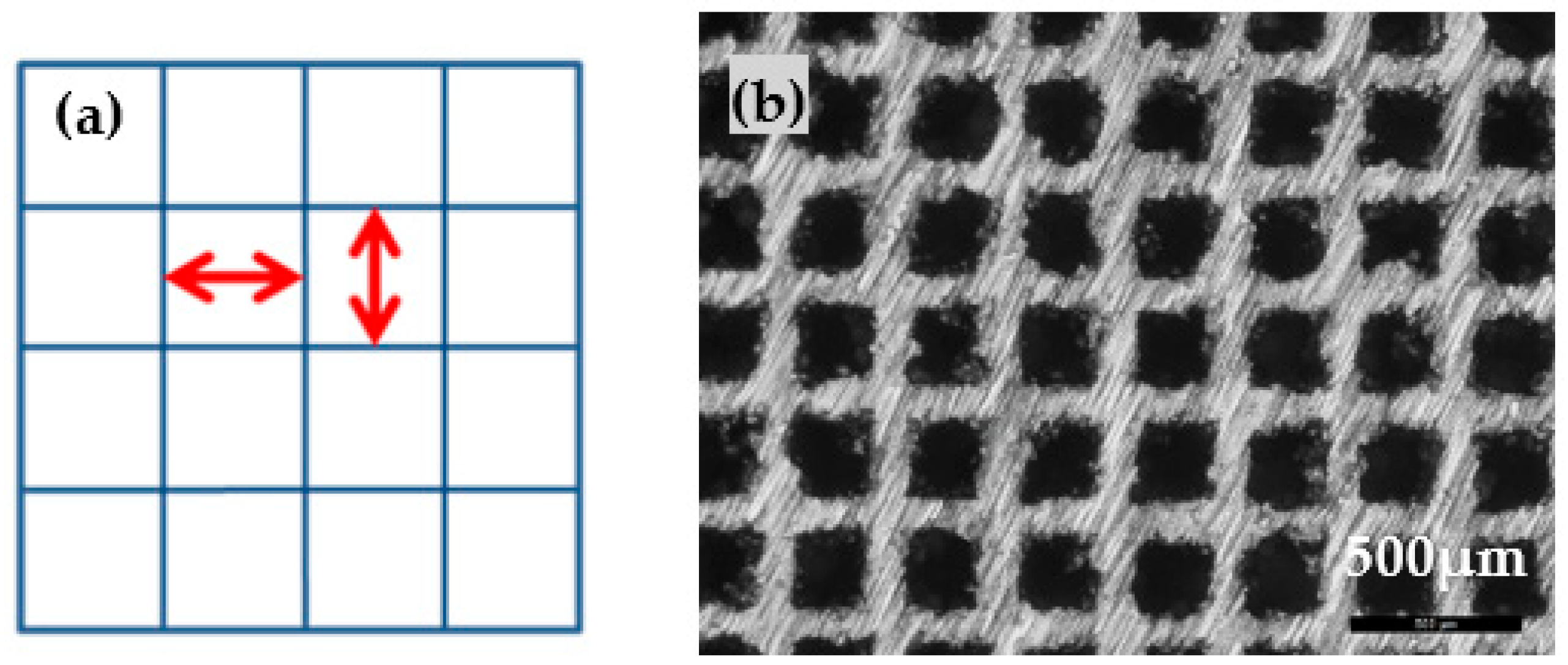
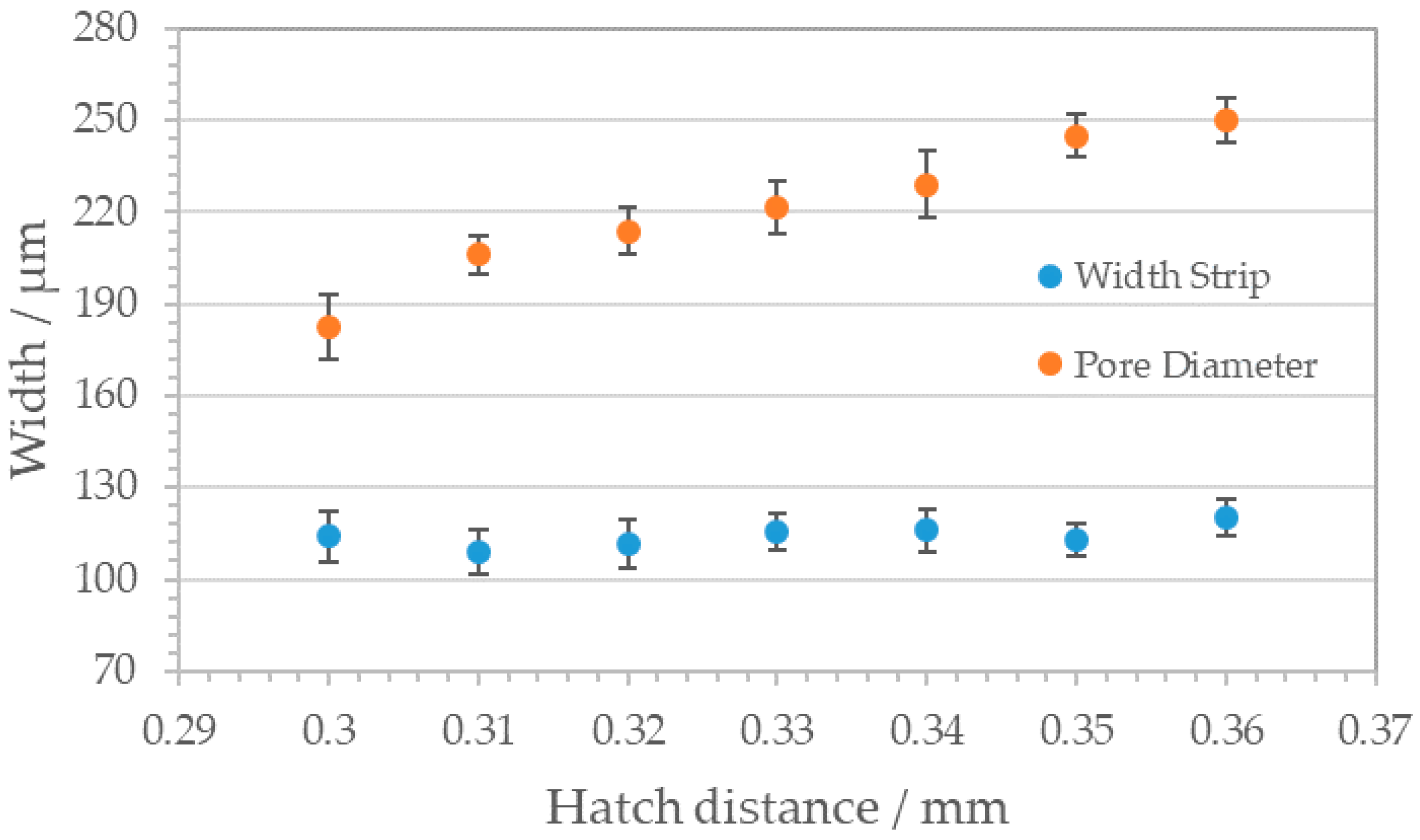
3.2. Square Pattern
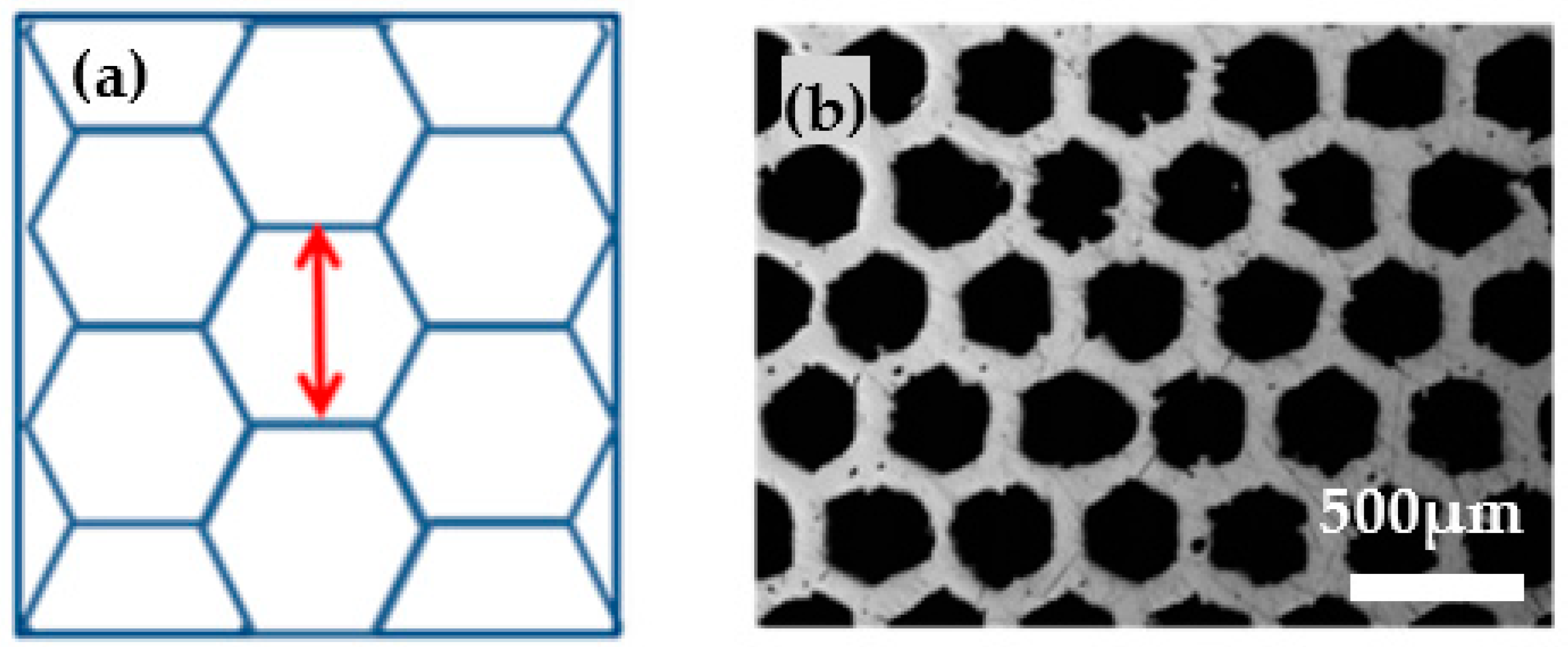
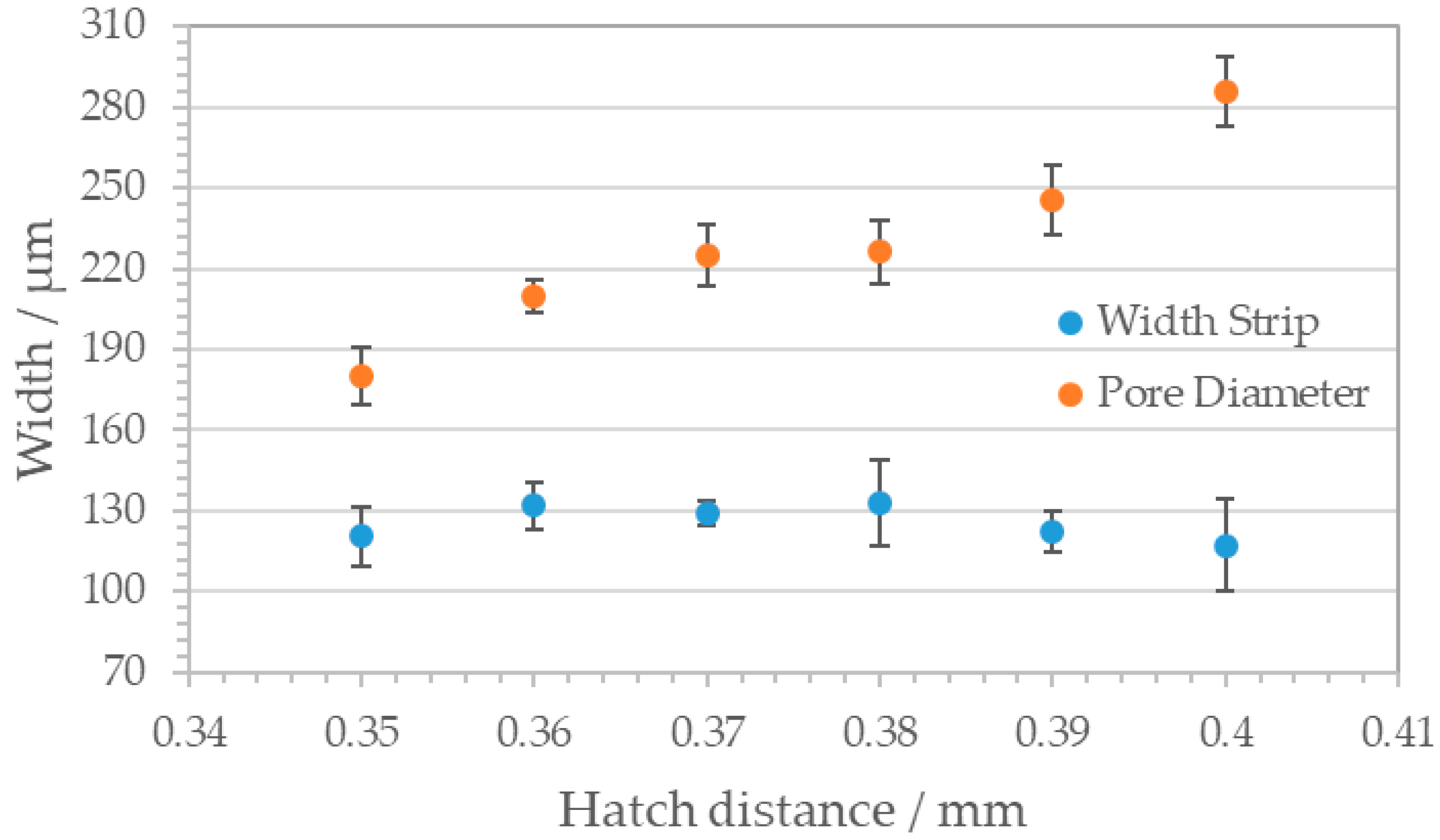
3.3. Honeycomb Pattern
3.4. Anisotropic Structure
4. Conclusions
Author Contributions
Funding
Conflicts of Interest
References
- Ngo, T.D.; Kashani, A.; Imbalzano, G.; Nguyen, K.T.Q.; Hui, D. Additive manufacturing (3D printing): A review of materials, methods, applications and challenges. Compos. Part B Eng. 2018, 143, 172–196. [Google Scholar] [CrossRef]
- Abdi, M.; Ashcroft, I.; Wildman, R.D. Design optimisation for an additively manufactured automotive component. IJPT 2018, 7, 142. [Google Scholar] [CrossRef]
- Mahmoud, D.; Elbestawi, M.A. Selective laser melting of porosity graded lattice structures for bone implants. Int. J. Adv. Manuf. Technol. 2019, 100, 2915–2927. [Google Scholar] [CrossRef]
- Maconachie, T.; Leary, M.; Lozanovski, B.; Zhang, X.; Qian, M.; Faruque, O.; Brandt, M. SLM lattice structures: Properties, performance, applications and challenges. Mater. Des. 2019, 183, 108137. [Google Scholar] [CrossRef]
- Yuan, L.; Ding, S.; Wen, C. Additive manufacturing technology for porous metal implant applications and triple minimal surface structures: A review. Bioact. Mater. 2019, 4, 56–70. [Google Scholar] [CrossRef]
- Blanco, D.; Rubio, E.M.; Marín, M.M.; Davim, J.P. Advanced materials and multi-materials applied in aeronautical and automotive fields: A systematic review approach. Procedia CIRP 2021, 99, 196–201. [Google Scholar] [CrossRef]
- Rehme, O.; Emmelmann, C. Rapid manufacturing of lattice structures with selective laser melting. In Laser-Based Micropackaging; International Society for Optics and Photonics: Bellingham, WA, USA, 2006; Volume 6107. [Google Scholar]
- De. Pasquale, G.; Luceri, F.; Riccio, M. Experimental Characterization of SLM and EBM Cubic Lattice Structures for Lightweight Applications. Exp. Mech. 2019, 59, 469–482. [Google Scholar] [CrossRef]
- Kranz, J.; Herzog, D.; Emmelmann, C. Design guidelines for laser additive manufacturing of lightweight structures in TiAl6V4. J. Laser Appl. 2015, 27, S14001. [Google Scholar] [CrossRef]
- Zhou, H.; Zhang, X.; Zeng, H.; Yang, H.; Lei, H.; Li, X.; Wang, Y. Lightweight structure of a phase-change thermal controller based on lattice cells manufactured by SLM. Chin. J. Aeronaut. 2019, 32, 1727–1732. [Google Scholar] [CrossRef]
- Spierings, A.B.; Dawson, K.; Kern, K.; Palm, F.; Wegener, K. SLM-processed Sc- and Zr- modified Al-Mg alloy: Mechanical properties and microstructural effects of heat treatment. Mater. Sci. Eng. A 2017, 701, 264–273. [Google Scholar] [CrossRef]
- Helou, M.; Kara, S. Design, analysis and manufacturing of lattice structures: An overview. Int. J. Comput. Integr. Manuf. 2018, 31, 243–261. [Google Scholar] [CrossRef]
- Hasib, H.; Rennie, A.; Burns, N.; Geekie, L. Non-stochastic lattice structures for novel filter applications fabricated via additive manufacturing. Filtration 2015, 15, 175–180. [Google Scholar]
- Leary, M.; Mazur, M.; Elambasseril, J.; McMillan, M.; Chirent, T.; Sun, Y.; Qian, M.; Easton, M.; Brandt, M. Selective laser melting (SLM) of AlSi12Mg lattice structures. Mater. Des. 2016, 98, 344–357. [Google Scholar] [CrossRef]
- Leary, M.; Mazur, M.; Williams, H.; Yang, E.; Alghamdi, A.; Lozanovski, B.; Zhang, X.; Shidid, D.; Farahbod-Sternahl, L.; Witt, G.; et al. Inconel 625 lattice structures manufactured by selective laser melting (SLM): Mechanical properties, deformation and failure modes. Mater. Des. 2018, 157, 179–199. [Google Scholar] [CrossRef]
- Mazur, M.; Leary, M.; Sun, S.; Vcelka, M.; Shidid, D.; Brandt, M. Deformation and failure behaviour of Ti-6Al-4V lattice structures manufactured by selective laser melting (SLM). Int. J. Adv. Manuf. Technol. 2015, 84, 1391–1411. [Google Scholar] [CrossRef]
- Su, X.; Yang, Y.; Xiao, D.; Luo, Z. An investigation into direct fabrication of fine-structured components by selective laser melting. Int. J. Adv. Manuf. Technol. 2013, 64, 1231–1238. [Google Scholar] [CrossRef]
- Wang, D.; Yang, Y.; Liu, R.; Xiao, D.; Sun, J. Study on the designing rules and processability of porous structure based on selective laser melting (SLM). J. Mater. Process. Technol. 2013, 213, 1734–1742. [Google Scholar] [CrossRef]
- Yan, C.; Hao, L.; Hussein, A.; Raymont, D. Evaluations of cellular lattice structures manufactured using selective laser melting. Int. J. Mach. Tools Manuf. 2012, 62, 32–38. [Google Scholar] [CrossRef]
- Caligno, F.; Cattano, G.; Iuliano, L.; Manfredi, D. Controlled Porosity Structures in Aluminum and Titanim Alloys by Selecive Laser Melting. In Industrializing Additive Manufacturing—Proceedings of Additive Manufacturing in Products and Applications—AMPA2017; Meboldt, M., Klahn, C., Eds.; Springer International Publishing: Cham, Switzerland, 2018; pp. 181–190. ISBN 978-3-319-66866-6. [Google Scholar]
- Yan, M.; Tian, X.; Peng, G.; Cao, Y.; Li, D. Hierarchically porous materials prepared by selective laser sintering. Mater. Des. 2017, 135, 62–68. [Google Scholar] [CrossRef]
- Klahn, C.; Bechmann, F.; Hofmann, S.; Dinkel, M.; Emmelmann, C. Laser Additive Manufacturing of Gas Permeable Structures. Phys. Procedia 2013, 41, 873–880. [Google Scholar] [CrossRef] [Green Version]
- Ambu, R.; Morabito, A.E. Design and analysis of tissue engineering scaffolds based on open porous non-stochastic cells. In Advances on Mechanics, Design Engineering and Manufacturing; Eynard, B., Nigrelli, V., Oliveri, S.M., Peris-Fajarnes, G., Rizzuti, S., Eds.; Springer International Publishing: Cham, Switzerland, 2017; pp. 777–787. ISBN 978-3-319-45780-2. [Google Scholar]
- Buechel, F.F.; Pappas, M.J. Properties of Materials Used in Orthopaedic Implant Systems. In Principles of Human Joint Replacement; Buechel, F., Pappas, M., Eds.; Springer International Publishing: Cham, Switzerland, 2015; pp. 1–32. ISBN 978-3-319-15310-0. [Google Scholar]
- Matena, J.; Petersen, S.; Gieseke, M.; Kampmann, A.; Teske, M.; Beyerbach, M.; Murua Escobar, H.; Haferkamp, H.; Gellrich, N.-C.; Nolte, I. SLM produced porous titanium implant improvements for enhanced vascularization and osteoblast seeding. Int. J. Mol. Sci. 2015, 16, 7478–7492. [Google Scholar] [CrossRef] [Green Version]
- Trautmann, A.; Rüth, M.; Lemke, H.-D.; Walther, T.; Hellmann, R. Two-photon polymerization based large scaffolds for adhesion and proliferation studies of human primary fibroblasts. Opt. Laser Technol. 2018, 106, 474–480. [Google Scholar] [CrossRef]
- Edelmann, A.; Dubis, M.; Hellmann, R. Selective Laser Melting of Patient Individualized Osteosynthesis Plates-Digital to Physical Process Chain. Materials 2020, 13, 5786. [Google Scholar] [CrossRef]
- Yan, X.; Li, Q.; Yin, S.; Chen, Z.; Jenkins, R.; Chen, C.; Wang, J.; Ma, W.; Bolot, R.; Lupoi, R.; et al. Mechanical and in vitro study of an isotropic Ti6Al4V lattice structure fabricated using selective laser melting. J. Alloys Compd. 2019, 782, 209–223. [Google Scholar] [CrossRef]
- Trevisan, F.; Calignano, F.; Aversa, A.; Marchese, G.; Lombardi, M.; Biamino, S.; Ugues, D.; Manfredi, D. Additive manufacturing of titanium alloys in the biomedical field: Processes, properties and applications. J. Appl. Biomater. Funct. Mater. 2018, 16, 57–67. [Google Scholar] [CrossRef]
- Habijan, T.; Haberland, C.; Meier, H.; Frenzel, J.; Wittsiepe, J.; Wuwer, C.; Greulich, C.; Schildhauer, T.A.; Köller, M. The biocompatibility of dense and porous Nickel-Titanium produced by selective laser melting. Mater. Sci. Eng. C Mater. Biol. Appl. 2013, 33, 419–426. [Google Scholar] [CrossRef]
- Wauthle, R.; van der Stok, J.; Amin Yavari, S.; van Humbeeck, J.; Kruth, J.-P.; Zadpoor, A.A.; Weinans, H.; Mulier, M.; Schrooten, J. Additively manufactured porous tantalum implants. Acta Biomater. 2015, 14, 217–225. [Google Scholar] [CrossRef] [PubMed]
- van Hengel, I.A.J.; Riool, M.; Fratila-Apachitei, L.E.; Witte-Bouma, J.; Farrell, E.; Zadpoor, A.A.; Zaat, S.A.J.; Apachitei, I. Selective laser melting porous metallic implants with immobilized silver nanoparticles kill and prevent biofilm formation by methicillin-resistant Staphylococcus aureus. Biomaterials 2017, 140, 1–15. [Google Scholar] [CrossRef] [PubMed]
- Qin, J.; Chen, Q.; Yang, C.; Huang, Y. Research process on property and application of metal porous materials. J. Alloys Compd. 2016, 654, 39–44. [Google Scholar] [CrossRef]
- Burns, N.; Burns, M.; Travis, D.; Geekie, L.; Rennie, A.E.W. Designing Advanced Filtration Media through Metal Additive Manufacturing. Chem. Eng. Technol. 2016, 39, 535–542. [Google Scholar] [CrossRef]
- Burns, N.R.; Burns, M.A.; Travis, D.; Geekie, L.E.; Rennie, A.E.W.; Weston, D. Novel Filter Designs that Deliver Filtration Benefits Produced by Metal Additive Manufacturing. In Proceedings of the American Filtration and Separations Society Fall Conference 2013: Innovations in Filter Media and Membranes, Cincinnati, OH, USA, 14–16 October 2013. [Google Scholar]
- Lee, S.H.W.; Choo, H.L.; Mok, S.H.; Cheng, X.Y.; Manurung, Y.H.P. Fabrication of Porous Metallic Materials by Controlling the Processing Parameters in Selective Lasermelting. AIP Conf. Proc. 2020, 2233, 020016. [Google Scholar]
- Fogliatto, A.A.B.; Ahrens, C.H.; Wendhausen, P.A.P.; Santos, E.C.; Rodrigues, D. Correlation between porosity and permeability of stainless steel filters with gradient porosity produced by SLS/SLM. Rapid Prototyp. J. 2020, 26, 73–81. [Google Scholar] [CrossRef]
- Niya, S.M.R.; Selvadurai, A.P.S. A Statistical Correlation Between Permeability, Porosity, Tortuosity and Conductance. Transp. Porous Med. 2018, 121, 741–752. [Google Scholar] [CrossRef]
- Medraj, M.; Baril, E.; Loya, V.; Lefebvre, L.-P. The effect of microstructure on the permeability of metallic foams. J. Mater. Sci. 2007, 42, 4372–4383. [Google Scholar] [CrossRef] [Green Version]
- Despois, J.; Mortensen, A. Permeability of open-pore microcellular materials. Acta Mater. 2005, 53, 1381–1388. [Google Scholar] [CrossRef] [Green Version]
- Wałowski, G. Assessment of gas permeability coefficient of porous materials. J. Sustain. Min. 2017, 16, 55–65. [Google Scholar] [CrossRef]
- Dlapka, M.; Danninger, H.; Gierl, C.; Lindqvist, B. Defining the pores in PM components. Met. Powder Rep. 2010, 65, 30–33. [Google Scholar] [CrossRef]
- Furumoto, T.; Koizumi, A.; Alkahari, M.R.; Anayama, R.; Hosokawa, A.; Tanaka, R.; Ueda, T. Permeability and strength of a porous metal structure fabricated by additive manufacturing. J. Mater. Process. Technol. 2015, 219, 10–16. [Google Scholar] [CrossRef]
- Guddati, S.; Kiran, A.S.K.; Leavy, M.; Ramakrishna, S. Recent advancements in additive manufacturing technologies for porous material applications. Int. J. Adv. Manuf. Technol. 2019, 105, 193–215. [Google Scholar] [CrossRef]
- Vadasz, P. Fluid Flow and Heat Transfer in Rotating Porous Media; Springer International Publishing: Cham, Switzerland, 2016; ISBN 978-3-319-20055-2. [Google Scholar]
- Civan, F. Stress-Dependent Porosity and Permeability of Porous Rocks Represented by a Mechanistic Elastic Cylindrical Pore-Shell Model. Transp. Porous Med. 2019, 129, 885–899. [Google Scholar] [CrossRef]
- van Bael, S.; Chai, Y.C.; Truscello, S.; Moesen, M.; Kerckhofs, G.; van Oosterwyck, H.; Kruth, J.-P.; Schrooten, J. The effect of pore geometry on the in vitro biological behavior of human periosteum-derived cells seeded on selective laser-melted Ti6Al4V bone scaffolds. Acta Biomater. 2012, 8, 2824–2834. [Google Scholar] [CrossRef] [PubMed]
- Cai, J.; Yu, B. A Discussion of the Effect of Tortuosity on the Capillary Imbibition in Porous Media. Transp. Porous Media 2011, 89, 251–263. [Google Scholar] [CrossRef]
- Neuman, S.P. Theoretical derivation of Darcy’s law. Acta Mech. 1977, 25, 153–170. [Google Scholar] [CrossRef]
- Chandrappa, A.K.; Biligiri, K.P. Comprehensive investigation of permeability characteristics of pervious concrete: A hydrodynamic approach. Constr. Build. Mater. 2016, 123, 627–637. [Google Scholar] [CrossRef]
- Kundu, P.; Kumar, V.; Mishra, I.M. Experimental and numerical investigation of fluid flow hydrodynamics in porous media: Characterization of pre-Darcy, Darcy and non-Darcy flow regimes. Powder Technol. 2016, 303, 278–291. [Google Scholar] [CrossRef]
- Pucci, M.; Liotier, P.; Drapier, S. Capillary wicking in flax fiber reinforcements; orthotropic issues and comparison with Carbon reinforcements. In Proceedings of the 20th International Conference on Composite Materials, Copenhagen, Denmark, 19–24 July 2015. [Google Scholar]
- Nield, D.A.; Bejan, A. Convection in Porous Media; Springer International Publishing: Cham, Switzerland, 2017; ISBN 978-3-319-49561-3. [Google Scholar]
- UNE-EN ISO 17892-11 Geotechnical Investigation and Testing—Laboratory Testing of Soil—Part 11: Permeability Tests (ISO 17892-11:2019); UNE-EN ISO 17892-11:2020-03-04; ISO copyright office: Geneva, Switzerland, 2020.
- Nakano, T. Selective Laser Melting. In Multi-dimensional Additive Manufacturing; Kirihara, S., Nakata, K., Eds.; Springer: Singapore, 2021; pp. 3–26. ISBN 978-981-15-7909-7. [Google Scholar]
- Herzog, D.; Seyda, V.; Wycisk, E.; Emmelmann, C. Additive manufacturing of metals. Acta Mater. 2016, 117, 371–392. [Google Scholar] [CrossRef]
- Yadroitsev, I.; Gusarov, A.; Yadroitsava, I.; Smurov, I. Single track formation in selective laser melting of metal powders. J. Mater. Process. Technol. 2010, 210, 1624–1631. [Google Scholar] [CrossRef]
- Yadroitsev, I.; Shishkovsky, I.; Bertrand, P.; Smurov, I. Manufacturing of fine-structured 3D porous filter elements by selective laser melting. Appl. Surf. Sci. 2009, 255, 5523–5527. [Google Scholar] [CrossRef]
- Ameli, M.; Agnew, B.; Leung, P.S.; Ng, B.; Sutcliffe, C.J.; Singh, J.; McGlen, R. A novel method for manufacturing sintered aluminium heat pipes (SAHP). Appl. Therm. Eng. 2013, 52, 498–504. [Google Scholar] [CrossRef]
- Joseph, J.; Siva Kumar Gunda, N.; Mitra, S.K. On-chip porous media: Porosity and permeability measurements. Chem. Eng. Sci. 2013, 99, 274–283. [Google Scholar] [CrossRef]
- Xie, Y.; Yang, H.; Wang, X.; Zhao, L.; Kuang, C.; Han, W. Control of wall thickness and surface morphology of tungsten thin wall parts by adjusting selective laser melting parameters. J. Iron Steel Res. Int. 2019, 26, 182–190. [Google Scholar] [CrossRef]
- Koponen, A.; Kataja, M.; Timonen, J. Permeability and effective porosity of porous media. Phys. Rev. E 1997, 56, 3319. [Google Scholar] [CrossRef]


Publisher’s Note: MDPI stays neutral with regard to jurisdictional claims in published maps and institutional affiliations. |
© 2021 by the authors. Licensee MDPI, Basel, Switzerland. This article is an open access article distributed under the terms and conditions of the Creative Commons Attribution (CC BY) license (https://creativecommons.org/licenses/by/4.0/).
Share and Cite
Goetzendorfer, B.; Kirchgaessner, H.; Hellmann, R. Tunable, Anisotropic Permeability and Spatial Flow of SLM Manufactured Structures. Materials 2021, 14, 5205. https://doi.org/10.3390/ma14185205
Goetzendorfer B, Kirchgaessner H, Hellmann R. Tunable, Anisotropic Permeability and Spatial Flow of SLM Manufactured Structures. Materials. 2021; 14(18):5205. https://doi.org/10.3390/ma14185205
Chicago/Turabian StyleGoetzendorfer, Babette, Hannah Kirchgaessner, and Ralf Hellmann. 2021. "Tunable, Anisotropic Permeability and Spatial Flow of SLM Manufactured Structures" Materials 14, no. 18: 5205. https://doi.org/10.3390/ma14185205