
Experimental Determination of the Coefficient of Restitution for Selected Modern Hybrid Composites


Abstract
:1. Introduction
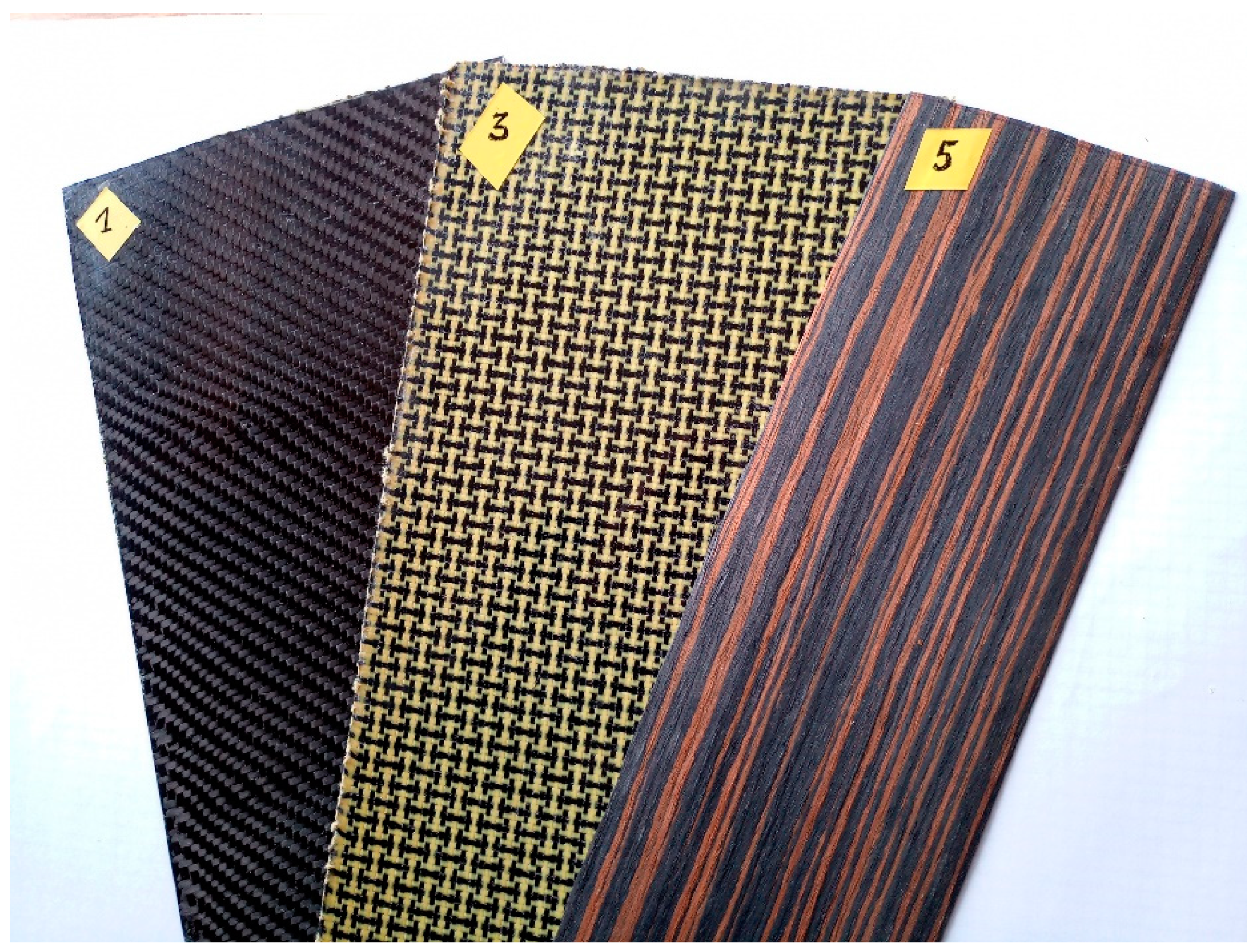
2. Materials
3. Test Stand and Course of the Experiment
- A ram equipped with an acceleration sensor;
- A guide tube for the ram during impact (not included in the figure);
- A holder with the tube attached (not included in the figure);
- A steel plate with a square cutout for fixing specimens.
- Acceleration by means of a sensor attached to the ram;
- Plate deflection by means of the distance sensors;
- The height of a rebound;
- Time between successive rebounds of the ram identified on the basis of the analysis of film frames.
4. Results and Discussion
- Δw′—relative velocity of the bodies after the collision,
- Δw—relative velocity of the bodies before the collision.
- —height reached by the ram after a rebound,
- —ram’s drop height.
- g—standard gravity,
- τ—time between rebounds.
- a—slope of the linear approximation of the dependence ε(h),
- b—intercept of the linear approximation of the dependence ε(h).
5. Conclusions
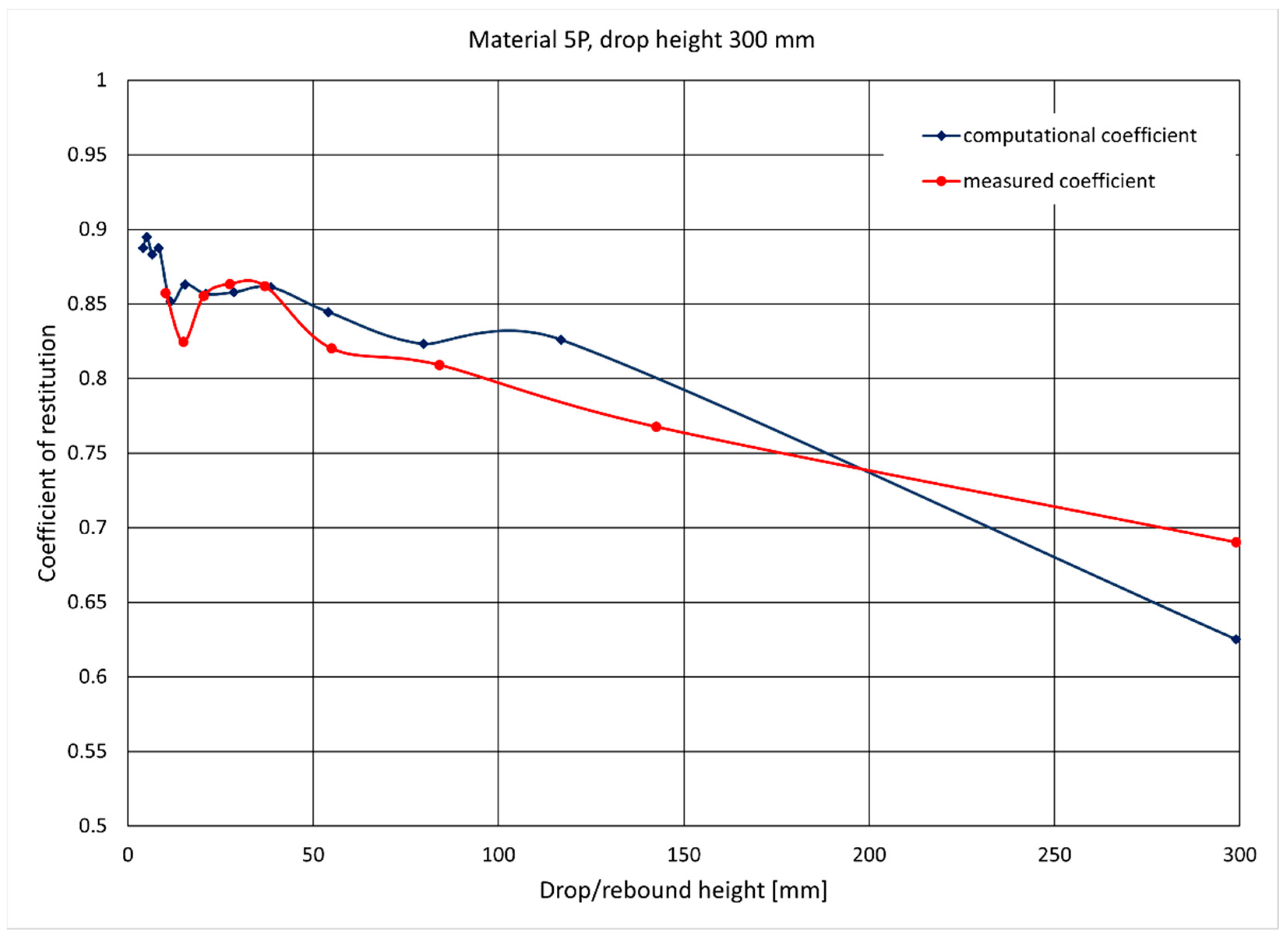
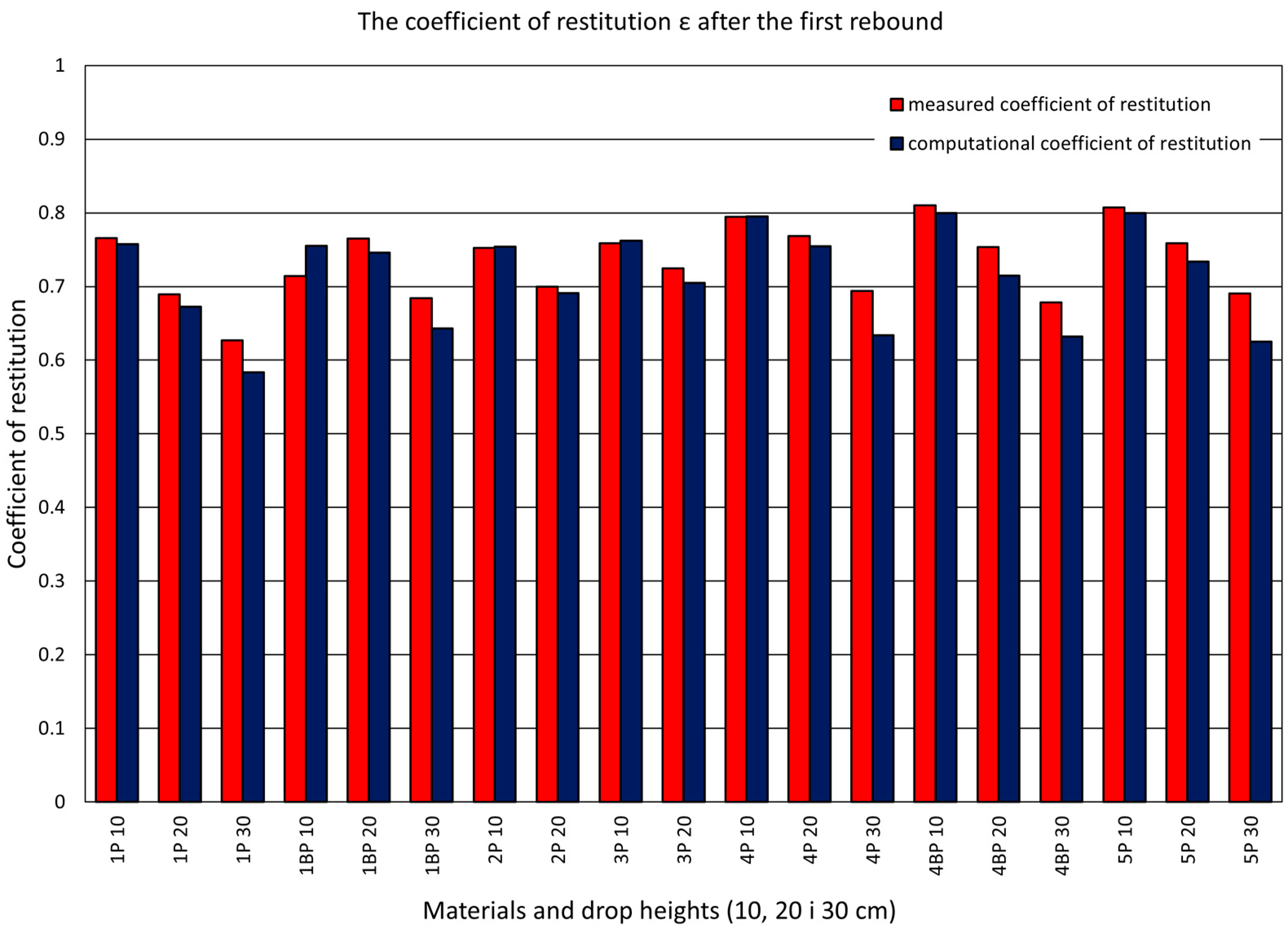
- The values of the coefficient of restitution obtained using two described methods, due to slight differences (6% on average), can be considered acceptable. This means that both measurement methods can be used interchangeably, but the authors emphasize that the computational method is a simpler method that requires less expensive equipment.
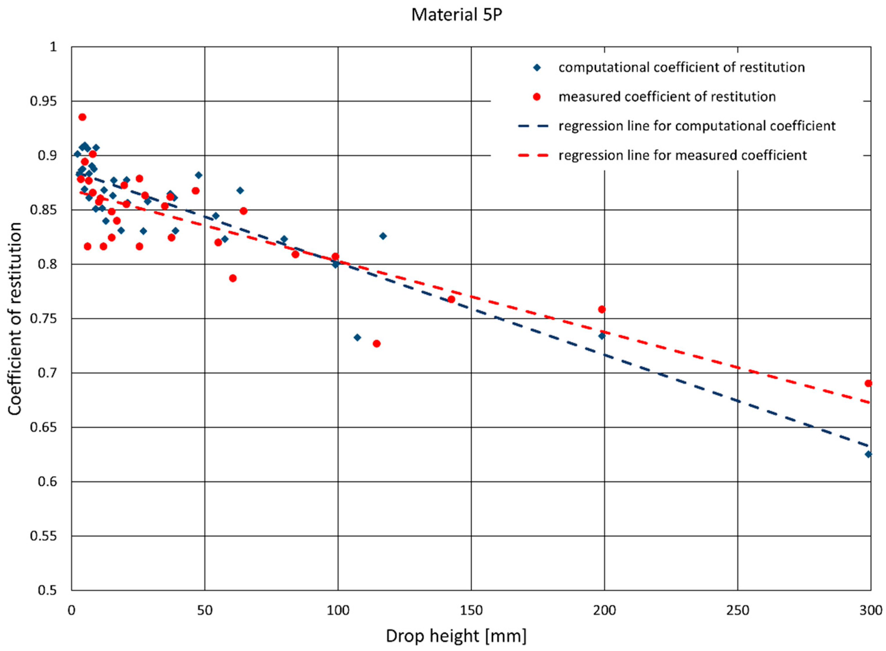
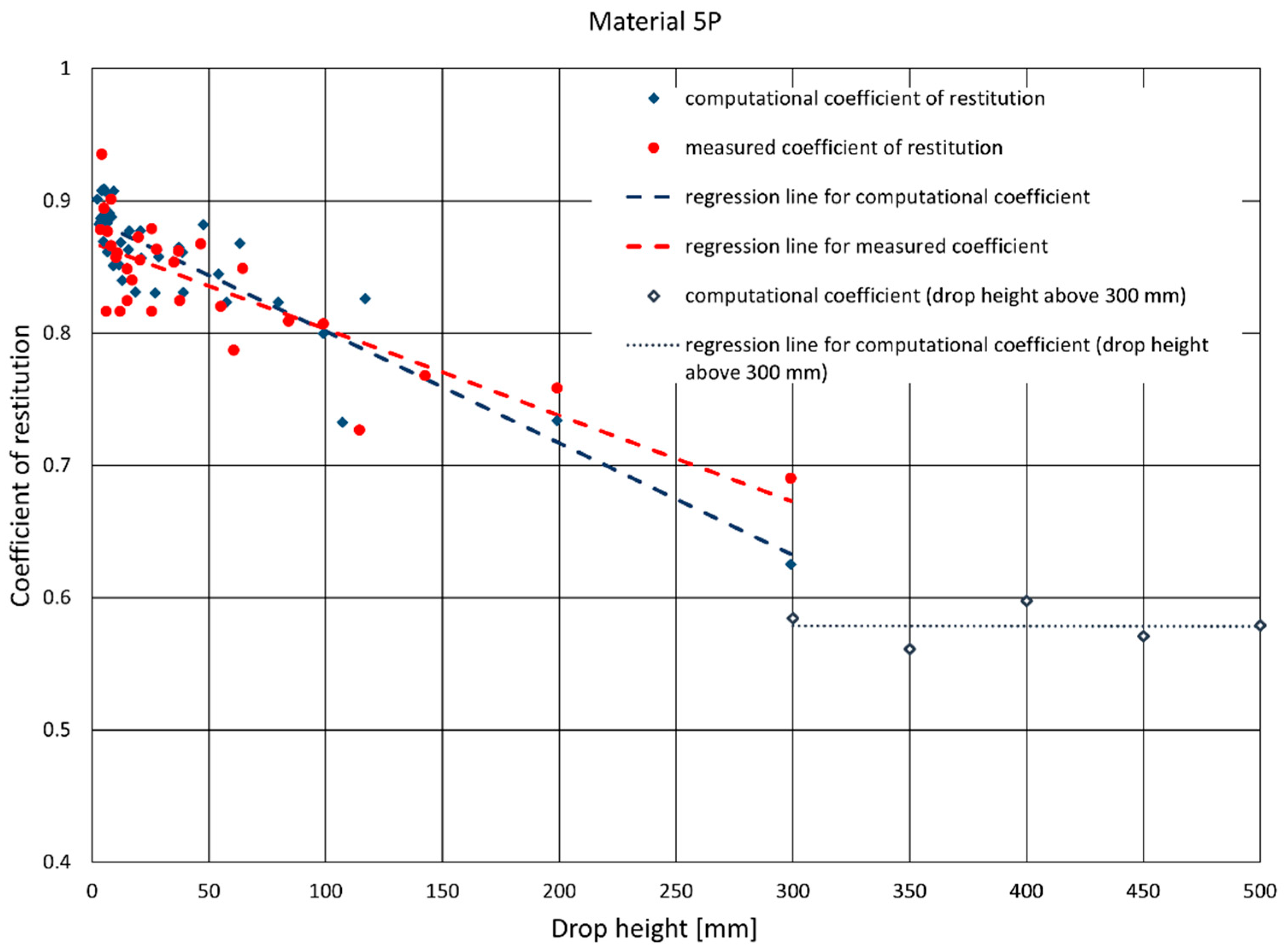
- The value of the coefficient of restitution changes as a function of the ram drop height. The greater the height, the smaller the value of the coefficient. In the authors’ opinion, this is so because, for greater heights more energy is dissipated during ever-greater deformations of the sample material. This is due to the micro-skid inside the composite structure. Such a situation will continue until the strength limit values are exceeded, resulting in the destruction of the sample.
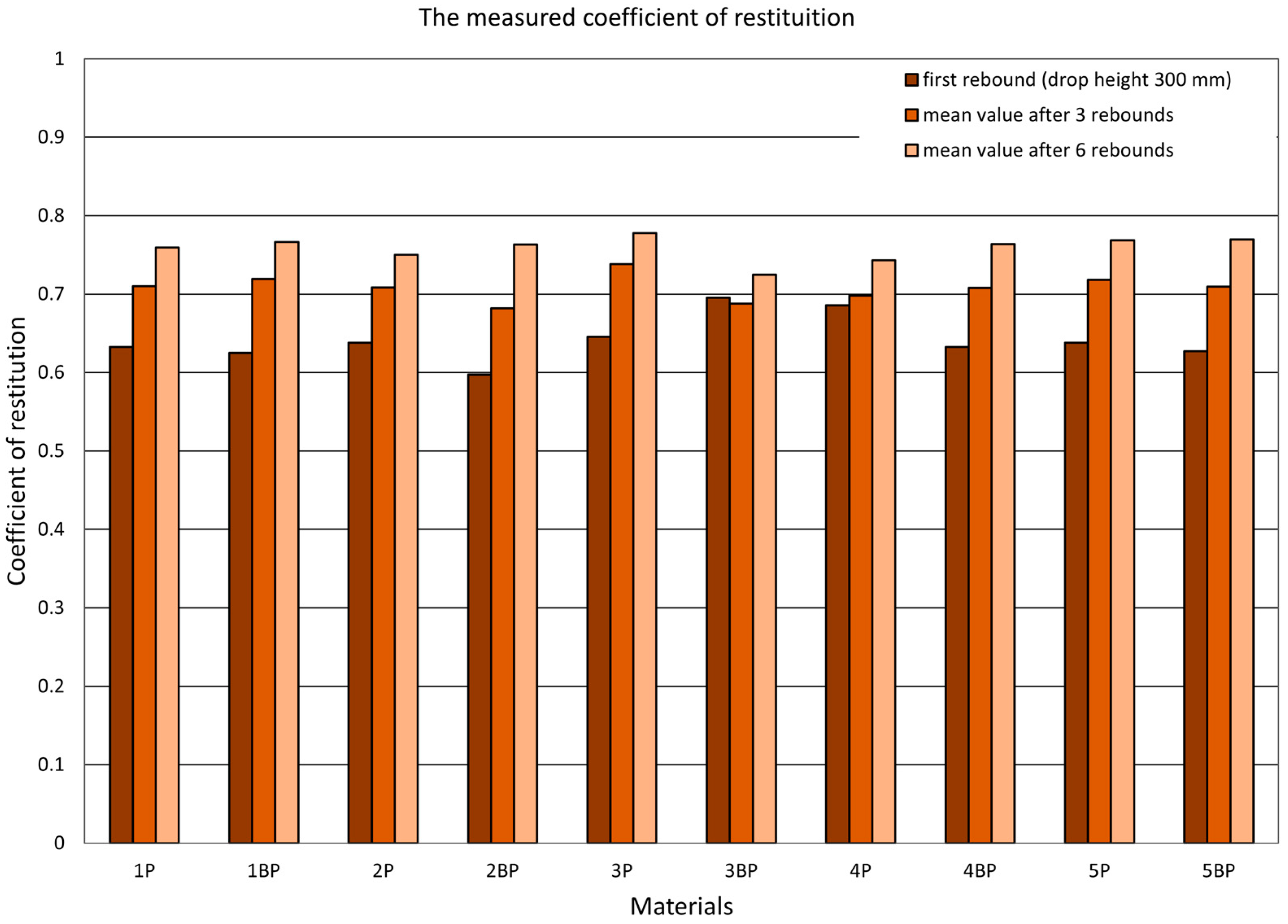
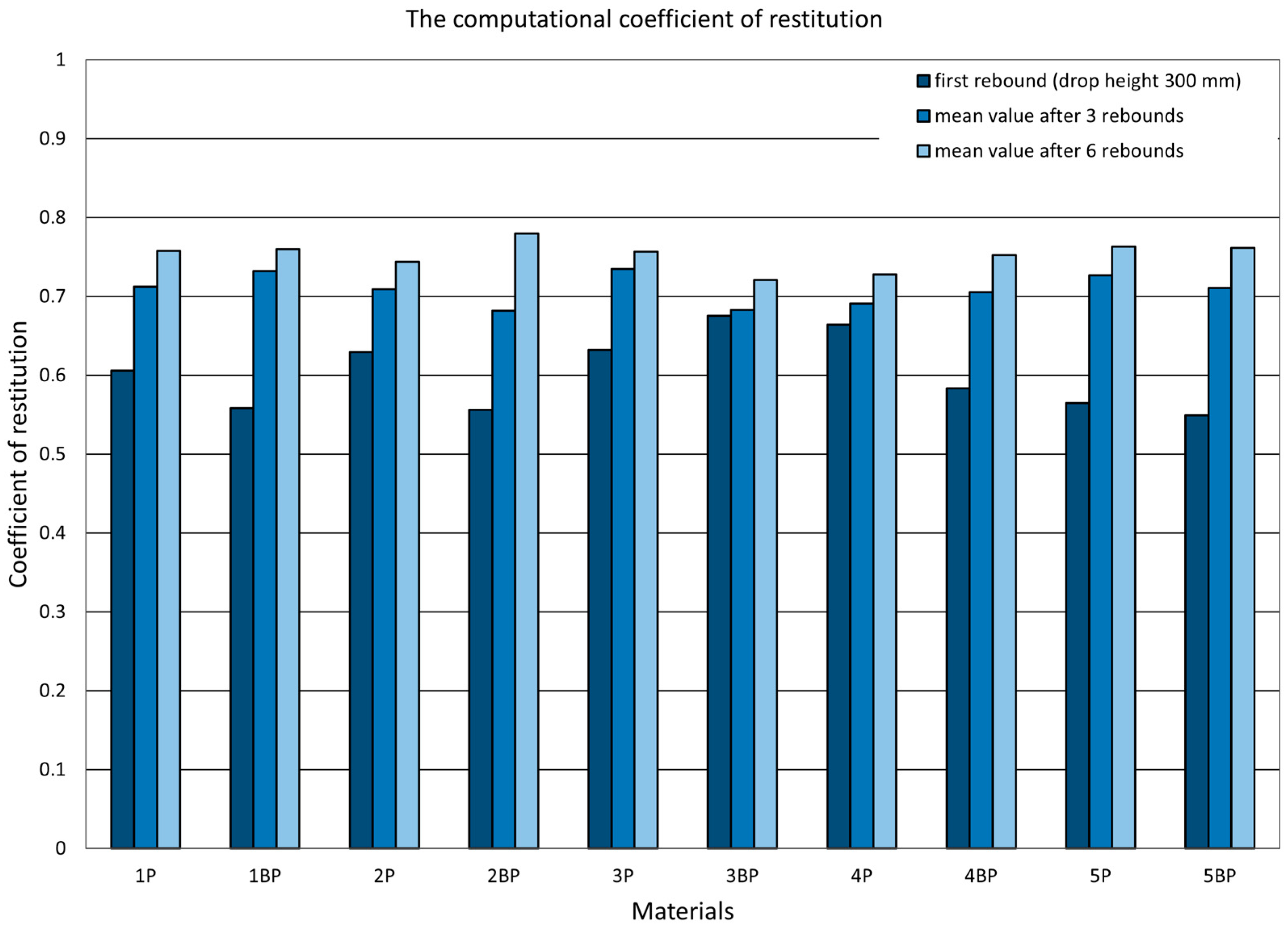
- The use of averaging over successive rebounds results in an increase (on average by 10–20% for the first three rebounds and by 20–25% for the first six rebounds for both methods) in the value of the restitution coefficient.
- The use of vacuum laminating technology results in a slight increase in the value of the coefficient of restitution (except for material 3P/BP). It follows that with better resin supersaturation (higher fiber/resin ratio) there should be lower internal damping in the composite. However, it is the type of reinforcement used rather than the production method that mainly affects the value of the coefficient of restitution of tested materials. Finally, it should be remembered that decisions regarding whether a high or a low coefficient of restitution is required depends primarily on the final application of the composite.
Author Contributions
Funding
Institutional Review Board Statement
Informed Consent Statement
Data Availability Statement
Conflicts of Interest
References
- Miedzińska, D. Numerical Modelling of Functionally Graded Composite Microstructure in Terms of Their Homogenization. Compos. Theory Pract. 2017, 17, 169–174. [Google Scholar]
- Kelly, A.; Zweben, C. Comprehensive composite materials. Mater. Today 1999, 2, 20–21. [Google Scholar] [CrossRef]
- Tuttle, M.T. A framework for long-term durability predictions of polymeric composites. In Progress in Durability Analysis of Composite Systems; A.A. Balkema: Rotterdam, The Netherlands, 1996; pp. 169–176. [Google Scholar]
- Wells, J.K.; Beaumont, P. Debonding and pull-out process in fibrous composites. J. Mater. Sci. 1985, 20, 1275–1284. [Google Scholar] [CrossRef]
- Canal, L.P.; Pappas, G.; Botsis, J. Large scale fiber bridging in mode I intralaminar fracture. An embedded cell approach. Compos. Sci. Technol. 2016, 126, 52–59. [Google Scholar] [CrossRef]
- Jankowski, R. Experimental study on earthquake-induced pounding between structural elements made of different building materials. Earthq. Eng. Struct. Dyn. 2010, 39, 343–354. [Google Scholar] [CrossRef]
- Hadryś, D.; Miros, M. Coefficient of restitution of model repaired car body parts. J. Achiev. Mater. Manuf. Eng. 2008, 28, 51–54. [Google Scholar]
- Skórski, W.W.; Zawisza, M. Influence of the composite modification of the wooden wing skin of the glider on deflection lines and resonance vibrations. Polimery 2019, 64, 267–271. [Google Scholar] [CrossRef] [Green Version]
- Obszański, M.; Skórski, W.W.; Zawisza, M. Application of Hybrid Shells in Elements of Vehicles, Aircrafts and Marine Vessels; Instytut Technologii Eksploatacji—Państwowy Instytut Badawczy: Radom, Poland, 2017; ISBN 978-83-7789-272-5. (In Polish) [Google Scholar]
- Li, C.; Yin, X.; Wang, Y.; Zhang, L.; Zhangg, Z.; Liu, Y.; Xian, G. Mechanical property evolution and service life prediction of pultruded carbon/glass hybrid rod exposed in harsh oil-well condition. Compos. Struct. 2020, 246, 112418. [Google Scholar] [CrossRef]
- Yadava, I.N.; Thapa, K.B. Strain-based theoretical fatigue damage model of woven glass-epoxy fabric composite material. Compos. Part C Open Access 2020, 3, 100067. [Google Scholar] [CrossRef]
- Talreja, R. Fatigue of Composite Materials; Technomic Publishing Company: Lancaster, PA, USA, 1987. [Google Scholar]
- Talreja, R.; Singh, C.V. Damage and Failure of Composite Materials; Cambridge University Press: New York, NY, USA, 2012. [Google Scholar]
- Rojek, M. Methodology of diagnostic testing of polymeric matrix laminate composite materials. Achiev. Mater. Sci. Eng. 2011, 2, 1–148. [Google Scholar]
- Lu, Z.; Li, J.; Xie, J.; Huang, P.; Xue, L. Durability of flexurally strengthened RC beams with prestressed CFRP sheet under wet–dry cycling in a chloride-containing environment. Compos. Struct. 2021, 255, 112869. [Google Scholar] [CrossRef]
- Durda, D.D.; Movshovitz, N.; Richardson, D.C.; Asphaug, E.; Morgan, A.; Rawlings, A.R.; Vest, C. Experimental determination of the coefficient of restitution for meter-scale granite spheres. Icarus 2011, 211, 849–855. [Google Scholar] [CrossRef]
- Borska, B.; Kulczycka, A. Analysis of dynamic load caused by the impact of free-falling mass. Masz. Górnicze 2014, 1, 14–21. [Google Scholar]
- Glielmo, A.; Gunkelmann, N.; Poschel, T. Coefficient of restitution of aspherical particles. Phys. Rev. E 2014, 90, 052204. [Google Scholar] [CrossRef] [PubMed] [Green Version]
- Stronge, W.J. Impact Mechanics; Cambridge University Press: Cambridge, UK, 2000. [Google Scholar]


| Material Number | Layers Configuration | Area Density (g/m2) (Reinforcement by Mass) | Thickness (mm) | Young’s Modulus (GPa) | Tensile Strength (MPa) | Flexibility (mm/N) | Notes (Technology) |
|---|---|---|---|---|---|---|---|
| 1 P | W + KW + W + KW | 1032 | 0.9 | 41.3 | 346 | 0.015 | Vacuum bag |
| 1 BP | W + KW + W + KW | 1725 | 1.4 | 35.6 | 301 | 0.012 | No vacuum bag |
| 2 P | W + S + W | 816 | 0.7 | 35.1 | 343 | 0.021 | Vacuum bag |
| 2 BP | W + S + W | 1279 | 1.0 | 27.6 | 251 | 0.02 | No vacuum bag |
| 3 P | KW + S + W | 805 | 0.7 | 30.9 | 324 | 0.025 | Vacuum bag |
| 3 BP | KW + S + W | 1273 | 1.0 | 24.1 | 258 | 0.019 | No vacuum bag |
| 4 P | W + F + KW | 986 | 1.1 | 19.9 | 167 | 0.018 | vacuum bag |
| 4 BP | W + F + KW | 1337 | 1.3 | 15.6 | 150 | 0.014 | no vacuum bag |
| 5 P | F + S + W + KW | 1240 | 1.3 | 24.1 | 214 | 0.023 | vacuum bag |
| 5 BP | F + S + W + KW | 1708 | 1.5 | 17.3 | 175 | 0.017 | no vacuum bag |
| Layer | Material | Grammage (g/m2) |
|---|---|---|
| F | Wood veneer | 343 |
| KW | Woven kevlar–carbon fabric (plain hybrid) | 165 |
| S | Woven glass fabric (plain weave) | 200 |
| W | Woven carbon fabric (plain weave) | 204 |
| In all cases the epoxy resin (EPOLAM 2017) was used as a matrix | ||
| Material | Coefficient of Restitution | Slope a | Intercept b | Correlation Coefficient | Standard Deviation of the Approximation |
|---|---|---|---|---|---|
| 1P | computational | −0.0011 | 0.8810 | 0.9432 | 0.0226 |
| measurement | −0.0008 | 0.8383 | 0.9520 | 0.0175 | |
| 1BP | computational | −0.0009 | 0.8835 | 0.8871 | 0.0284 |
| measurement | −0.0007 | 0.8624 | 0.8028 | 0.0358 | |
| 2P | computational | −0.0011 | 0.8895 | 0.9501 | 0.0164 |
| measurement | −0.0007 | 0.8401 | 0.7924 | 0.0270 | |
| 3P | computational | −0.0012 | 0.9131 | 0.8649 | 0.0332 |
| measurement | −0.0007 | 0.8533 | 0.8128 | 0.0260 | |
| 4P | computational | −0.0007 | 0.8819 | 0.9415 | 0.0154 |
| measurement | −0.0006 | 0.8721 | 0.9144 | 0.0178 | |
| 4BP | computational | −0.0006 | 0.8850 | 0.7903 | 0.0202 |
| measurement | −0.0006 | 0.8752 | 0.7743 | 0.0227 | |
| 5P | computational | −0.0008 | 0.8861 | 0.9126 | 0.0227 |
| measurement | −0.0007 | 0.8683 | 0.8267 | 0.0294 |
Publisher’s Note: MDPI stays neutral with regard to jurisdictional claims in published maps and institutional affiliations. |
© 2021 by the authors. Licensee MDPI, Basel, Switzerland. This article is an open access article distributed under the terms and conditions of the Creative Commons Attribution (CC BY) license (https://creativecommons.org/licenses/by/4.0/).
Share and Cite
Skórski, W.W.; Obszański, M.; Zawisza, M. Experimental Determination of the Coefficient of Restitution for Selected Modern Hybrid Composites. Materials 2021, 14, 5638. https://doi.org/10.3390/ma14195638
Skórski WW, Obszański M, Zawisza M. Experimental Determination of the Coefficient of Restitution for Selected Modern Hybrid Composites. Materials. 2021; 14(19):5638. https://doi.org/10.3390/ma14195638
Chicago/Turabian StyleSkórski, Witold Wojciech, Marcin Obszański, and Maciej Zawisza. 2021. "Experimental Determination of the Coefficient of Restitution for Selected Modern Hybrid Composites" Materials 14, no. 19: 5638. https://doi.org/10.3390/ma14195638
APA StyleSkórski, W. W., Obszański, M., & Zawisza, M. (2021). Experimental Determination of the Coefficient of Restitution for Selected Modern Hybrid Composites. Materials, 14(19), 5638. https://doi.org/10.3390/ma14195638